EP0412754A1 - Imprimante thermique - Google Patents
Imprimante thermique Download PDFInfo
- Publication number
- EP0412754A1 EP0412754A1 EP90308640A EP90308640A EP0412754A1 EP 0412754 A1 EP0412754 A1 EP 0412754A1 EP 90308640 A EP90308640 A EP 90308640A EP 90308640 A EP90308640 A EP 90308640A EP 0412754 A1 EP0412754 A1 EP 0412754A1
- Authority
- EP
- European Patent Office
- Prior art keywords
- printing
- speed
- current
- hysteresis
- thermal
- Prior art date
- Legal status (The legal status is an assumption and is not a legal conclusion. Google has not performed a legal analysis and makes no representation as to the accuracy of the status listed.)
- Granted
Links
- 238000007639 printing Methods 0.000 claims abstract description 131
- 238000010438 heat treatment Methods 0.000 claims abstract description 40
- 238000007651 thermal printing Methods 0.000 claims abstract description 16
- 230000004044 response Effects 0.000 claims description 5
- 238000000034 method Methods 0.000 description 4
- 238000001816 cooling Methods 0.000 description 3
- 230000000593 degrading effect Effects 0.000 description 2
- FGRBYDKOBBBPOI-UHFFFAOYSA-N 10,10-dioxo-2-[4-(N-phenylanilino)phenyl]thioxanthen-9-one Chemical compound O=C1c2ccccc2S(=O)(=O)c2ccc(cc12)-c1ccc(cc1)N(c1ccccc1)c1ccccc1 FGRBYDKOBBBPOI-UHFFFAOYSA-N 0.000 description 1
- 238000010586 diagram Methods 0.000 description 1
Images


Classifications
-
- B—PERFORMING OPERATIONS; TRANSPORTING
- B41—PRINTING; LINING MACHINES; TYPEWRITERS; STAMPS
- B41J—TYPEWRITERS; SELECTIVE PRINTING MECHANISMS, i.e. MECHANISMS PRINTING OTHERWISE THAN FROM A FORME; CORRECTION OF TYPOGRAPHICAL ERRORS
- B41J2/00—Typewriters or selective printing mechanisms characterised by the printing or marking process for which they are designed
- B41J2/315—Typewriters or selective printing mechanisms characterised by the printing or marking process for which they are designed characterised by selective application of heat to a heat sensitive printing or impression-transfer material
- B41J2/32—Typewriters or selective printing mechanisms characterised by the printing or marking process for which they are designed characterised by selective application of heat to a heat sensitive printing or impression-transfer material using thermal heads
- B41J2/35—Typewriters or selective printing mechanisms characterised by the printing or marking process for which they are designed characterised by selective application of heat to a heat sensitive printing or impression-transfer material using thermal heads providing current or voltage to the thermal head
Definitions
- the present invention relates to a thermal printer, and more particularly to the thermal printer which has at least two printing speed modes, that is, a high-speed mode and a low-speed mode to be selectively switched and is capable of variably controlling a time when current flows through each necessary dot heating element contained in a thermal printing head.
- the normal thermal printer includes a thermal printing head containing dot heating elements disposed in a vertical line.
- these dot heating elements are selectively heated to form a character as the thermal printing head travels in the printing direction at a predetermined pitch.
- one character is printed by the dots for character each time the thermal printing head is travelled by the predetermined number of dots.
- some character patterns may allow the same dot heating elements to be kept heating. The surfaces of these heating elements are heated up too much because of the condensed heat thereon. It results in disadvantageously causing the printed characters to have variable density, remarkably lowering character quality, and degrading the dot heating elements.
- Fig.1 is a chart illustrating a table for managing the printing hysteresis of the current bit to the fourth previous bit, wherein O denotes printing, X denotes non-printing, and - denotes "Don't Care”.
- Fig. 2 is a chart illustrating pulse widths T1 to T5 defined according to the printing hysteresis illustrated in Fig. 1 . It is clearly understood from these charts that as the previous printing is further than the current printing, the larger pulse width is used for the current printing.
- the larger pulse width can expand the time when current flows through each necessary dot heating element in order to conform with the fact that the longer time interval from the current printing to the next results in the longer cooling time of the dot heating elements. It results in achieving substantially uniform density on printed characters.
- this kind of thermal printer is designed to switch the printing speed to a high-speed printing mode or a low-speed mode.
- the foregoing table corresponds with the high-speed printing mode at which the dot heating elements do not have enough cooling time because of a shorter printing period.
- the dot heating elements operated three bits previous have already cooled down because of the foregoing longer printing period. It is, therefore, unnecessary to manage the printing hysteresis before the third previous bit, though, the printing is operated on the table for the high-speed printing mode. It means that when the printing is done before the third previous bit, the time when current flows through each necessary dot heating element is made shorter than a proper time, resulting in making the printed characters thinner in density.
- the thermal printer provides the table corresponding with the low-speed printing mode, in the high-speed printing mode, excessive energy is applied on the dot heating elements, thereby rapidly degrading the thermal printing head and reducing the life of the head.
- a thermal printer including a thermal printing head provided with dot heating elements and a switch for switching the printing mode from a high-speed mode to a low-speed one or vice versa, which includes a high-speed printing table containing pulse widths respectively for the printing hysteresis of the current bit to the N-th previous bit, a low-speed printing table containing pulse widths respectively for the printing hysteresis of the current bit to the M-th previous bit, the M being smaller than said N, and means for selecting any one of both two tables in response to the selected printing speed mode, determining the printing hysteresis of the current bit to the N-th bit or M-th previous bit, having access to each necessary address location for the pulse width on the selected table on the basis of the printing hysteresis, and adjusting the time when current flows through each necessary dot heating element to the time defined by the pulse width contained in the selected table.
- the present thermal printer operates to select the mode, determine the printing hysteresis of the current bit to the N-th previous bit, have access to the time-width address location on the high-speed printing table according to the printing hysteresis, and pass current through each necessary dot heating element contained in the thermal printing head for a time defined by the accessed time width.
- the present thermal printer operates to select the mode, determine the printing hysteresis of the current bit to the M-th previous bit, have access to the time-width address location on the low-speed printing table according to the printing hysteresis, and pass current through each necessary dot heating element contained in the thermal printing head for a time defined by the accessed pulse width.
- the thermal printer of this invention provides the high-speed printing table and the low-speed printing table which respectively contain the printing hysteresis and the pulse width matched to the printing hysteresis of the high-speed or the low-speed printing mode.
- the printer operates to select the proper table for the printing speed mode. Hence, it can constantly apply proper energy to the dot heating elements contained in the printing head in a manner to adapt to the various conditions so that it can achieve uniform density for printed characters. Further, the printer can keep the life of the thermal printing head as long as possible, because it serves to positively refrain application of excessive energy which would otherwise degrade the thermal printing head overly.
- a thermal printer related to the embodiment with reference to Fig. 3.
- 1 denotes a central processing unit (abbreviated as a CPU), which serves to control the printer in accordance with a program stored in a read-only memory 4.
- the CPU 1 serves to process text data entered on a keyboard 2 and send the result to a random access memory (abbreviated as a RAM) 3.
- the RAM 3 temporarily stores the processed text data.
- the CPU 1 reads the text data from the RAM 3 to a printing control circuit 5.
- the printing control circuit 5 reads each character contained in the text data, that is, a character pattern at a predetermined row and column from a character generator 6 and then continuously outputs each column data of the character pattern to a head driver 10.
- the head driver 10 controls a thermal head providing dot heating elements so that it may selectively pass current through the dot heating elements corresponding to the column data.
- the CPU 1 sends out a motor-driving pulse to a carriage driver 8 through the printing control circuit 5 so that the carriage driver 8 can operate a carriage motor 9 one pitch by one pitch, thereby travelling the thermal head 11 in the printing direction one pitch by one pitch.
- the printing control circuit 5 serves to have access to the corresponding address locations contained in the table 7a or 7b.
- the address locations to be accessed correspond to the printing hysteresis of the current bit to the N-th or M-th previous bit and concerns with the pulse widths. Then, the printing control circuit 5 serves to pass current through each dot heating element for the time defined by the pulse width of the accessed address location.
- Fig. 5 is a chart illustrating the high-speed printing table 7a for managing the printing hysteresis of the current bit to the N-th previous bit.
- Fig. 7 is a chart illustrating the low-speed printing table 7b for managing the printing hysteresis of the current bit to the M-th previous bit.
- O denotes printing
- X denotes non-printing
- - denotes "Don't Care”.
- the pulse widths defined for the printing hysteresis is illustrated in Figs. 6 and 8.
- the previous bit from the current bit matches to a pulse width T1
- the second previous bit from the current bit matches to a pulse width T1 + T2
- the third previous bit from the current bit matches to a pulse width T1 + T2 + T3,... ... the (N-2)th previous bit from the current bit matches to a pulse width T1 + ... ... + T N-2
- the (N-1)th previous bit from the current bit matches to a pulse width T1 + ... ... + T N-1
- the N previous bit from the current bit matches to a pulse width T1 + ... ... + T N .
- These pulse widths individually matched to the previous bits are made smaller as the bit are more previous from the current bit.
- N and M are computed from each printing period defined in the high-speed printing mode.
- the arrangement is analogous to that of the table 7a except that the pulse width is represented by t and the most previous bit to be managed is M.
- N for the high-speed printing mode is larger than M for the low-speed printing mode, because the numbers N and M are computed from the printing period and in the high-speed printing mode, the printing period, that is, a head-cooling period is shorter than that in the low-speed printing mode.
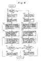
- the thermal printer operates on the flow shown in Fig.4.
- the printing control circuit 5 determines if the high-speed printing mode is specified (step S1). If it is specified, the circuit 5 selects the high-speed printing table 7a from the table memory 7 (step S2). Then, the circuit 5 reads the first column data of the character pattern for the printing character from the character generator 6 (step S3). This first column data corresponds to the heating-commanded dot heating elements contained in the thermal printing head 11. Next, the circuit 5 checks the printing hysteresis of the current bit to the Nth previous bit about the heating-commanded dot heating elements in the first column data (step S4).
- the circuit 5 has access to the address locations for pulse widths on the high-speed printing table 7a according to the checked printing hysteresis (step S5). It controls the head driver 10 to allow the current to pass through each heating-commanded dot heating element for the time defined by the pulse width of the accessed address location (step S6). Finally, the thermal head 11 serves to thermally record the dots.
- step S7 After the thermal recording, it is determined if all the characters to be printed are printed (step S7). If not, the printing control circuit 5 reads the next column data of the character pattern (step S8). Then, the process jumps to the step S4, where the operation is executed from the steps S4 to S8 until the printing is finished.
- the printing control circuit 5 selects the low-speed printing table 7b from the table memory 7 (step S12) and then reads the first column data of the character pattern for the printing character from the character generator 6 (step S13). This first column data corresponds to the heating-commanded dot heating elements contained in the thermal printing head 11. Next, the circuit 5 checks the printing current bit to the M previous bit about the heating-commanded dot heating elements of the first column data (step S14).
- the circuit 5 has access to the address locations for pulse widths on the low-speed printing table 7b according to the checked printing hysteresis (step S15). It controls the head driver 10 to allow the current to pass through each heating-commanded dot heating element for the time defined by the pulse width of the accessed address location (step S16). Finally, the thermal head 11 serves to thermally record the dots.
- step S17 After the thermal recording, it is determined if all the characters to be printed are printed (step S17). If not, the printing control circuit 5 reads the next column data of the character pattern (step S18). Then, the process jumps to the step S4, where the operation is executed from the steps S4 to S8 until the printing is finished.
- the thermal printer of the present invention provides the high-speed printing table and the low-speed printing table respectively having the printing hysteresis and the pulse width matching to the high-speed and low-speed mode printing periods, so that it can select one of these tables according to the printing speed mode.
- the printer is capable of constantly applying proper energy to each dot heating element of the printing head in a manner to adapt to the various conditions, resulting in being able to print high-quality, that is, uniform-density characters as well as positively refrain application of excessive energy which would otherwise degrade the thermal printing head overly.
Landscapes
- Electronic Switches (AREA)
- Fax Reproducing Arrangements (AREA)
Applications Claiming Priority (2)
| Application Number | Priority Date | Filing Date | Title |
|---|---|---|---|
| JP204276/89 | 1989-08-07 | ||
| JP1204276A JP2523188B2 (ja) | 1989-08-07 | 1989-08-07 | サ―マルプリンタの印字制御方法 |
Publications (2)
| Publication Number | Publication Date |
|---|---|
| EP0412754A1 true EP0412754A1 (fr) | 1991-02-13 |
| EP0412754B1 EP0412754B1 (fr) | 1994-10-26 |
Family
ID=16487801
Family Applications (1)
| Application Number | Title | Priority Date | Filing Date |
|---|---|---|---|
| EP90308640A Expired - Lifetime EP0412754B1 (fr) | 1989-08-07 | 1990-08-06 | Imprimante thermique |
Country Status (4)
| Country | Link |
|---|---|
| US (1) | US5184150A (fr) |
| EP (1) | EP0412754B1 (fr) |
| JP (1) | JP2523188B2 (fr) |
| DE (1) | DE69013611T2 (fr) |
Families Citing this family (17)
| Publication number | Priority date | Publication date | Assignee | Title |
|---|---|---|---|---|
| JP2701997B2 (ja) * | 1991-02-26 | 1998-01-21 | ローム株式会社 | サーマルヘッドの駆動制御方法及び駆動制御装置 |
| US5644351A (en) * | 1992-12-04 | 1997-07-01 | Matsushita Electric Industrial Co., Ltd. | Thermal gradation printing apparatus |
| US5524993A (en) * | 1993-10-06 | 1996-06-11 | Monarch Marking Systems, Inc. | Automatic print speed control for a barcode printer |
| US6102593A (en) * | 1999-04-16 | 2000-08-15 | International Business Machines Corporation | High speed print quality font modification |
| US6999202B2 (en) | 2001-03-27 | 2006-02-14 | Polaroid Corporation | Method for generating a halftone of a source image |
| US6842186B2 (en) * | 2001-05-30 | 2005-01-11 | Polaroid Corporation | High speed photo-printing apparatus |
| ATE303901T1 (de) * | 2001-05-30 | 2005-09-15 | Polaroid Corp | Hochgeschwindigkeitsphotodruckgerät |
| US6937365B2 (en) | 2001-05-30 | 2005-08-30 | Polaroid Corporation | Rendering images utilizing adaptive error diffusion |
| US6819347B2 (en) | 2001-08-22 | 2004-11-16 | Polaroid Corporation | Thermal response correction system |
| US7176953B2 (en) | 2001-08-22 | 2007-02-13 | Polaroid Corporation | Thermal response correction system |
| US7295224B2 (en) * | 2001-08-22 | 2007-11-13 | Polaroid Corporation | Thermal response correction system |
| US7298387B2 (en) * | 2001-08-22 | 2007-11-20 | Polaroid Corporation | Thermal response correction system |
| US6906736B2 (en) * | 2002-02-19 | 2005-06-14 | Polaroid Corporation | Technique for printing a color image |
| US7283666B2 (en) | 2003-02-27 | 2007-10-16 | Saquib Suhail S | Digital image exposure correction |
| US8773685B2 (en) | 2003-07-01 | 2014-07-08 | Intellectual Ventures I Llc | High-speed digital image printing system |
| US7542060B2 (en) * | 2005-07-25 | 2009-06-02 | Seiko Epson Corporation | Thermal printer and thermal printer control method |
| JP5098365B2 (ja) * | 2007-03-02 | 2012-12-12 | セイコーエプソン株式会社 | 電子機器、及び電子機器に搭載された電動機の制御方法 |
Citations (5)
| Publication number | Priority date | Publication date | Assignee | Title |
|---|---|---|---|---|
| EP0115841A2 (fr) * | 1983-02-08 | 1984-08-15 | Hitachi, Ltd. | Imprimante thermique |
| EP0194676A2 (fr) * | 1985-03-12 | 1986-09-17 | Tokyo Electric Co., Ltd. | Imprimante à chaleur |
| EP0304916A1 (fr) * | 1987-08-28 | 1989-03-01 | Nec Corporation | Circuit de contrôle pour l'impression thermique |
| US4843409A (en) * | 1986-07-22 | 1989-06-27 | Konishiroku Photo Industry Co., Ltd. | Thermal transfer printer |
| US4845514A (en) * | 1986-09-19 | 1989-07-04 | Shinko Electric Co., Ltd. | Thermal transfer type line printer capable of setting printing density by command supplied from an external device |
Family Cites Families (8)
| Publication number | Priority date | Publication date | Assignee | Title |
|---|---|---|---|---|
| JPS6036397B2 (ja) * | 1980-03-31 | 1985-08-20 | 株式会社東芝 | 熱記録装置 |
| JPS59182758A (ja) * | 1983-04-01 | 1984-10-17 | Fuji Xerox Co Ltd | サ−マルヘツドの駆動回路 |
| US4574293A (en) * | 1983-05-23 | 1986-03-04 | Fuji Xerox Co., Ltd. | Compensation for heat accumulation in a thermal head |
| JPS6255164A (ja) * | 1985-09-04 | 1987-03-10 | Seiko Epson Corp | サ−マルプリンタ |
| JPS6255163A (ja) * | 1985-09-04 | 1987-03-10 | Seiko Epson Corp | サ−マルプリンタ |
| JPS6264572A (ja) * | 1985-09-17 | 1987-03-23 | Seiko Epson Corp | サ−マルプリンタ |
| US4912485A (en) * | 1987-01-28 | 1990-03-27 | Seiko Epson Corporation | Print controlling apparatus for a thermal printer |
| JPH0764069B2 (ja) * | 1987-03-13 | 1995-07-12 | キヤノン株式会社 | 電子機器 |
-
1989
- 1989-08-07 JP JP1204276A patent/JP2523188B2/ja not_active Expired - Fee Related
-
1990
- 1990-08-03 US US07/562,193 patent/US5184150A/en not_active Expired - Lifetime
- 1990-08-06 DE DE69013611T patent/DE69013611T2/de not_active Expired - Lifetime
- 1990-08-06 EP EP90308640A patent/EP0412754B1/fr not_active Expired - Lifetime
Patent Citations (5)
| Publication number | Priority date | Publication date | Assignee | Title |
|---|---|---|---|---|
| EP0115841A2 (fr) * | 1983-02-08 | 1984-08-15 | Hitachi, Ltd. | Imprimante thermique |
| EP0194676A2 (fr) * | 1985-03-12 | 1986-09-17 | Tokyo Electric Co., Ltd. | Imprimante à chaleur |
| US4843409A (en) * | 1986-07-22 | 1989-06-27 | Konishiroku Photo Industry Co., Ltd. | Thermal transfer printer |
| US4845514A (en) * | 1986-09-19 | 1989-07-04 | Shinko Electric Co., Ltd. | Thermal transfer type line printer capable of setting printing density by command supplied from an external device |
| EP0304916A1 (fr) * | 1987-08-28 | 1989-03-01 | Nec Corporation | Circuit de contrôle pour l'impression thermique |
Also Published As
| Publication number | Publication date |
|---|---|
| US5184150A (en) | 1993-02-02 |
| DE69013611D1 (de) | 1994-12-01 |
| JP2523188B2 (ja) | 1996-08-07 |
| EP0412754B1 (fr) | 1994-10-26 |
| JPH0367664A (ja) | 1991-03-22 |
| DE69013611T2 (de) | 1995-05-24 |
Similar Documents
| Publication | Publication Date | Title |
|---|---|---|
| US5184150A (en) | Thermal printer for providing printed characters with a uniform density | |
| US6034705A (en) | Thermal printer control system | |
| US5400058A (en) | Thermal print head control for printing serial bar codes | |
| EP0304916B1 (fr) | Circuit de contrôle pour l'impression thermique | |
| US4843409A (en) | Thermal transfer printer | |
| JPS63203348A (ja) | サ−マルプリンタの印字制御装置 | |
| JP3084452B2 (ja) | ラインサーマルプリンター | |
| EP0160318A2 (fr) | Système à imprimer pour une imprimante en matrice de points | |
| JPH07178948A (ja) | サーマルプリンタ | |
| US4809019A (en) | Character generator for thermal printers | |
| US5020927A (en) | Grouping of dot data in a multiple column dot-matrix printer | |
| JPS642076B2 (fr) | ||
| EP0501707B1 (fr) | Dispositif de commande pour tête d'impression thermique | |
| JPS62198468A (ja) | ドツトプリンタ | |
| JP2739694B2 (ja) | サーマルプリンタ及びその印字処理方法 | |
| JPH01306262A (ja) | サーマルヘッド制御装置 | |
| US6375300B1 (en) | Interleave pulse modulation for thermal printers | |
| JP2555105B2 (ja) | 印刷装置 | |
| JPH06990A (ja) | 印字制御装置 | |
| JPH0624944U (ja) | サーマルヘッドの制御装置 | |
| JP2760303B2 (ja) | サーマルヘッド駆動装置 | |
| JPS6153956B2 (fr) | ||
| US5127753A (en) | Printer with area defined and character defined erasing patterns | |
| JPS6116632B2 (fr) | ||
| JPS61287769A (ja) | 感熱転写階調制御装置 |
Legal Events
| Date | Code | Title | Description |
|---|---|---|---|
| PUAI | Public reference made under article 153(3) epc to a published international application that has entered the european phase |
Free format text: ORIGINAL CODE: 0009012 |
|
| AK | Designated contracting states |
Kind code of ref document: A1 Designated state(s): DE GB |
|
| 17P | Request for examination filed |
Effective date: 19901220 |
|
| 17Q | First examination report despatched |
Effective date: 19921026 |
|
| GRAA | (expected) grant |
Free format text: ORIGINAL CODE: 0009210 |
|
| AK | Designated contracting states |
Kind code of ref document: B1 Designated state(s): DE GB |
|
| REF | Corresponds to: |
Ref document number: 69013611 Country of ref document: DE Date of ref document: 19941201 |
|
| PLBE | No opposition filed within time limit |
Free format text: ORIGINAL CODE: 0009261 |
|
| STAA | Information on the status of an ep patent application or granted ep patent |
Free format text: STATUS: NO OPPOSITION FILED WITHIN TIME LIMIT |
|
| 26N | No opposition filed | ||
| REG | Reference to a national code |
Ref country code: GB Ref legal event code: IF02 |
|
| PGFP | Annual fee paid to national office [announced via postgrant information from national office to epo] |
Ref country code: GB Payment date: 20090805 Year of fee payment: 20 Ref country code: DE Payment date: 20090730 Year of fee payment: 20 |
|
| REG | Reference to a national code |
Ref country code: GB Ref legal event code: PE20 Expiry date: 20100805 |
|
| PG25 | Lapsed in a contracting state [announced via postgrant information from national office to epo] |
Ref country code: GB Free format text: LAPSE BECAUSE OF EXPIRATION OF PROTECTION Effective date: 20100805 |
|
| PG25 | Lapsed in a contracting state [announced via postgrant information from national office to epo] |
Ref country code: DE Free format text: LAPSE BECAUSE OF EXPIRATION OF PROTECTION Effective date: 20100806 |