EP0412845B1 - Implant dentaire - Google Patents
Implant dentaire Download PDFInfo
- Publication number
- EP0412845B1 EP0412845B1 EP90308845A EP90308845A EP0412845B1 EP 0412845 B1 EP0412845 B1 EP 0412845B1 EP 90308845 A EP90308845 A EP 90308845A EP 90308845 A EP90308845 A EP 90308845A EP 0412845 B1 EP0412845 B1 EP 0412845B1
- Authority
- EP
- European Patent Office
- Prior art keywords
- anchor
- passage
- body portion
- dental implant
- grooves
- Prior art date
- Legal status (The legal status is an assumption and is not a legal conclusion. Google has not performed a legal analysis and makes no representation as to the accuracy of the status listed.)
- Revoked
Links
- 239000004053 dental implant Substances 0.000 title claims description 21
- 210000000988 bone and bone Anatomy 0.000 claims description 18
- 238000003780 insertion Methods 0.000 claims description 8
- 230000037431 insertion Effects 0.000 claims description 8
- 239000007943 implant Substances 0.000 claims description 7
- 238000004873 anchoring Methods 0.000 claims description 4
- 230000008468 bone growth Effects 0.000 claims description 2
- 230000012010 growth Effects 0.000 claims description 2
- 210000001519 tissue Anatomy 0.000 description 3
- 239000008280 blood Substances 0.000 description 2
- 210000004369 blood Anatomy 0.000 description 2
- 239000000463 material Substances 0.000 description 2
- 238000010079 rubber tapping Methods 0.000 description 2
- 229910001069 Ti alloy Inorganic materials 0.000 description 1
- RTAQQCXQSZGOHL-UHFFFAOYSA-N Titanium Chemical compound [Ti] RTAQQCXQSZGOHL-UHFFFAOYSA-N 0.000 description 1
- XAGFODPZIPBFFR-UHFFFAOYSA-N aluminium Chemical compound [Al] XAGFODPZIPBFFR-UHFFFAOYSA-N 0.000 description 1
- 229910052782 aluminium Inorganic materials 0.000 description 1
- 239000000316 bone substitute Substances 0.000 description 1
- 238000000576 coating method Methods 0.000 description 1
- 230000000295 complement effect Effects 0.000 description 1
- 230000002708 enhancing effect Effects 0.000 description 1
- 229910052588 hydroxylapatite Inorganic materials 0.000 description 1
- 230000001788 irregular Effects 0.000 description 1
- 238000000034 method Methods 0.000 description 1
- XYJRXVWERLGGKC-UHFFFAOYSA-D pentacalcium;hydroxide;triphosphate Chemical compound [OH-].[Ca+2].[Ca+2].[Ca+2].[Ca+2].[Ca+2].[O-]P([O-])([O-])=O.[O-]P([O-])([O-])=O.[O-]P([O-])([O-])=O XYJRXVWERLGGKC-UHFFFAOYSA-D 0.000 description 1
- 229910052719 titanium Inorganic materials 0.000 description 1
- 239000010936 titanium Substances 0.000 description 1
- 229910052720 vanadium Inorganic materials 0.000 description 1
- LEONUFNNVUYDNQ-UHFFFAOYSA-N vanadium atom Chemical compound [V] LEONUFNNVUYDNQ-UHFFFAOYSA-N 0.000 description 1
Images

Classifications
-
- A—HUMAN NECESSITIES
- A61—MEDICAL OR VETERINARY SCIENCE; HYGIENE
- A61C—DENTISTRY; APPARATUS OR METHODS FOR ORAL OR DENTAL HYGIENE
- A61C8/00—Means to be fixed to the jaw-bone for consolidating natural teeth or for fixing dental prostheses thereon; Dental implants; Implanting tools
- A61C8/0089—Implanting tools or instruments
-
- A—HUMAN NECESSITIES
- A61—MEDICAL OR VETERINARY SCIENCE; HYGIENE
- A61C—DENTISTRY; APPARATUS OR METHODS FOR ORAL OR DENTAL HYGIENE
- A61C8/00—Means to be fixed to the jaw-bone for consolidating natural teeth or for fixing dental prostheses thereon; Dental implants; Implanting tools
- A61C8/0018—Means to be fixed to the jaw-bone for consolidating natural teeth or for fixing dental prostheses thereon; Dental implants; Implanting tools characterised by the shape
- A61C8/0022—Self-screwing
Definitions
- GB-A-2 199 502 discloses a dental implant anchor comprising a substantially cylindrical body portion for fitting in a passage formed in bone tissue, the body portion having an external wall portion carrying a plurality of circumferential or partially circumferential projections, each projection having a cross-section sufficiently large to engage frictionally the sidewalls of a said passage to hold the anchor inside the passage immediately upon insertion into the passage, each of the circumferential projections having a groove on each side for facilitating growth of bone tissue into the grooves for anchoring of the dental implant anchor in a said passage, and, apically of the projections, an external wall portion carrying a thread at an oblique angle to the longitudinal axis of the anchor for screwing into the end of the passage.
- the present invention provides such an anchor characterised in that it further comprises at least two longitudinally extending grooves passing through and interrupting each projection, the longitudinal grooves being of sufficient depth and width to ensure bone growth into the grooves when the anchor is in the passage; Preferably, these grooves are about 0.25 mm to about 1.5 mm in depth and in width.
- This anchor preferably includes a top portion with the body portion carrying the plurality of anchoring means on its outer wall.
- the top portion has a smooth external wall that tapers upwardly and outwardly from the body portion to a diameter that is slightly larger than the diameter of the body portion.
- the top portion is sufficiently large in diameter to insure that the top portion fits snugly within, and tightly seals, by frictional forces, in the top of a passage formed in bone tissue to receive the dental implant anchor
- the top portion can be of substantially the same diameter as, or even of smaller diameter than the body portion of the implant.
- the dental implant anchor preferably includes, at its distal end, a through hole extending from one side of the body portion to the other to permit bone and associated tissue to grow through this opening.
- the distal end preferably also includes a passage at the bottom of the body portion that extends. upwardly inside the body portion a distance sufficient to permit blood and other tissue to pass upwardly, out the through-hole and up the longitudinally-oriented grooves, thus allowing the anchor to seat at the bottom of the passage formed in bone tissue to receive the implant.
- this upwardly-extending passage is less than about one-third the length of the body portion.
- the anchor preferably has an internal passage extending downwardly from the top of the implant, and internal means for engaging and inserting the anchor into a passage formed in bone tissue to receive the implant.
- the internal anchor-engaging means permits insertion of the anchor in a passage formed in the bone tissue of a subject without countersinking the upper surface of the bone tissue, where the top portion of the anchor fits upon insertion of the anchor into such a passage.
- This internal means is, preferably, a wrench-engaging surface.
- the internal means for anchor insertion is inside this top portion.
- this internal means can be inside the body portion in an internal passage.
- the top portion has a hex nut configuration on its inner wall surfaces for receiving a hex wrench, and has a cylindrically-shaped, smooth outer wall.
- the hex nut configuration can be within, and at or near the base of the passage inside the body portion, or formed within threads on the wall of this passage.
- the top porticn is open, and can be chamfered at its upper end, and is preferably axially aligned with an internal passage in the body portion.
- the passage can be threaded or unthreaded.
- This chamfered surface permits frictional locking with any adaptor or other insert fitted into the opening.
- the chamfered surface is preferably of sufficient size and depth to afford lateral stability to any adaptor or other insert fitted into the opening in the head portion, and forms a smooth, easily-cleaned margin with complementary adaptors placed in the top portion of the anchor.
- the anchor is preferably made of titanium or a titanium alloy containing 6% by weight of aluminum and 4% by weight of vanadium; preferably has an outside thread diameter in the range of about 3 to about 4.25 millimeters; an inside thread diameter in the range of about 2.25 to about 3.5 millimeters; and preferably has projections with an outside diameter that is substantially the same as, or about 0.25 millimeter larger than the thread diameter.
- the anchor preferably has a length in the range of about 5 to 20 millimeters.
- the implant anchors of this invention are adapted for insertion in specially-formed passages in bone tissue.
- the method of forming such a passage includes forming a passage in the bone tissue having an upper portion with a length and a diameter suitable for engaging the circumferential or partially circumferential projections on the anchor by friction, and including, at the base of the passage, a smaller-diameter portion adapted to engage the self-tapping threads at the bottom of the anchor.
- the smaller-diameter portion at the base of the opening can be formed using a first drill having a cross-section appropriate to form a passage of this diameter and with length that is about the same as the length of the anchor to be inserted.
- the upper portion of the passage can be enlarged by a drill of appropriate diameter to accomodate the part of the body portion of the anchor with the circumferential or partially circumferential projections.
- the smaller diameter and larger diameter portions of the passage can be formed simultaneously using a drill having, at its end, a portion of a diameter appropriate for forming the smaller diameter portion of the passage, and an upper portion of larger diameter suitable for forming the upper portion of the passage.
- the implant anchor is tapped into the passage so formed until the bottom of the threaded portion reaches the top of the portion of smaller diameter at the base of the passage. Then, using an insertion tool to engage the wrench-engaging surface inside the anchor the anchor can be screwed into the smaller-diameter part of the passage until the threaded part of the anchor reaches the bottom of the passage.
- FIG. 1 shows a first type of known dental implant anchor generally designated 10.
- Anchor 10 includes body portion 11 joined to, and surmounted by top portion 12.
- Body portion 11 includes circumferential projection 16, called a flute, spaced from top portion 12 by circumferential groove 20 on body portion 11.
- Below flute 16 on body portion 11 are threads 15.
- At the bottom of body portion 11 is through-hole 14 which passes axially through body portion 11, and apical hole 13, formed at the bottom of anchor 10, and extending upwardly inside body portion 11 beyond through-hole 14.
- Top portion 12 is joined to, and surmounts body portion 11.
- Top portion 12 has a sidewall 17 that tapers upwardly and outwardly from the plane, near groove 20, where body portion 11 joins top portion 12.
- Atop top portion 2 is opening 19 with wrench-engaging surface 18 on the inner wall of top portion 12.
- This wrench-engaging surface 18 permits threading of anchoru 10 into a passage formed in bone tissue by means of a tool that fits inside anchor 10, obviating the need for any insertion tool-engaging means on the outside surface of anchor 10.
- Opening 19 can, in some embodiments, be in registration with a shaft formed inside body portion 11, and the wrench-engaging surface 18 can, in such embodiments, be at or near the base of the shaft internal to anchor 10.
- Fig. 2 shows a second type of known anchor , generally designated 32, that includes head portion 30 and body portion 31.
- Body portion 31 includes an external wall portion carrying a plurality of circumferential projections 33, 34, 35, 36, 37, 38 and 39. These projections are in planes parallel to one another and are separated from one another by grooves 40, 41, 42, 43, 44 and 45.
- Below circumferential flutes 33-39 is another wall portion carrying threads 46. The flutes facilitate seating the anchor frictionally in a passage formed in bone tissue by tapping the anchor into such a passage. Threads 46 at the bottom of body portion 31 permit the anchor to be screwed into the bottom of such a passage.
- Anchor 32 also includes through hole 47 and apical opening 48 which correspond to, and perform the same functions as openings 13 and 14, respectively, in Fig. 1.
- Top portion 30 includes opening 50 and wrench-engaging surface 51, which are identical to, and function the same as opening 19 in wrench-engaging surface 18, respectively, in Fig. 1.
- the opening 50 may be in registration with a shaft internal to body portion 31, and the wrench-engaging surface 51 can lie inside the shaft instead of inside head portion 30.
- Fig. 3 shows a third type of the known dental implant anchor.
- this anchor is identical to the anchor shown in Fig. 1, except that the internal wrench-engaging surface 19' lies at the bottom of the internal passage inside the anchor instead of on the internal surfaces of the top portion of the anchor.
- Fig. 3 shows the internal passage, below the top portion, to be partially threaded to receive and engage with threaded or unthreaded inserts such as dental prostheses, the threading is not mandatory, and the walls of the internal passage can, in alternative embodiments, be smooth instead of threaded, or partly threaded or partly smooth.
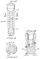
- Fig. 4 shows the embodiment of the new dental implant anchor.
- the anchor, of Fig. 4 is identical to those shown in Figs. 2 and 3.
- the outer wall surfaces 100 (Fig. 4) of this anchor 102 have two longitudinally-extending grooves 105/106 (Fig. 4) that are diametrically disposed on opposite sides of the other wall and that extend from just below the base of the top portion entirely through the circumferential projections from top to bottom. These grooves interrupt, and extend across and through these circumferential projections on each side of the anchor.
- These grooves are of sufficient depth and width, here about 0.25 mm to about 1.5 mm in depth (see Fig. 4B) and in width (see Fig. 4A), to insure that bone tissue will grow into these grooves enhancing the anchoring of the anchors to the bone tissue.
- the rounded flutes provide a surface adapted to receive coatings of material such as hydroxyl apatite or other bone substitute materials.
- the flutes also provide irregular surfaces for better distribution of stresses on the anchor from dental prostheses attached thereto.
- the upwardly, outwardly tapered head portion insures that anchor when inserted in a passage formed in bone tissue of sufficient depth to receive the entire anchor, seats firmly and snugly at the mouth of the passage.
- the openings and the longitudinally-oriented grooves permit blood and other tissue at the bottom of a passage formed in bone tissue to receive these anchors to pass upwardly so that the anchors can seat fully at the bottom of such a passage.
Landscapes
- Health & Medical Sciences (AREA)
- Oral & Maxillofacial Surgery (AREA)
- Orthopedic Medicine & Surgery (AREA)
- Dentistry (AREA)
- Epidemiology (AREA)
- Life Sciences & Earth Sciences (AREA)
- Animal Behavior & Ethology (AREA)
- General Health & Medical Sciences (AREA)
- Public Health (AREA)
- Veterinary Medicine (AREA)
- Dental Prosthetics (AREA)
- Prostheses (AREA)
Claims (7)
- Ancrage (102) pour implant dentaire sensiblement cylindrique, comportant une portion formant corps sensiblement cylindrique destinée à être placée dans un passage ménagé dans un tissu osseux, cette portion faisant corps comportant une portion de paroi extérieure (100) portant une multiplicité de saillies circonférentielles ou partiellement circonférentielles, chaque saillie ayant une section droite suffisamment grande pour engager avec frottement les parois latérales dudit passage afin de maintenir l'ancrage à l'intérieur du passage immédiatement après son insertion dans ce dernier, chacune des saillies circonférentielles comportant une rainure sur chaque côté pour faciliter la croissance du tissu osseux à l'intérieur de ces rainures afin d'ancrer l'implant dentaire dans ledit passage et, plus près de l'extrémité de l'ancrage que les saillies, une portion de paroi extérieure portant un filetage faisant un angle oblique par rapport à l'axe longitudinal de l'ancrage pour être vissé dans l'extrémité du passage, caractérisé en ce que l'ancrage comporte en outre au moins deux rainures s'étendant longitudinalement en (105, 106) passant à travers et interrompant chaque saillie, ces rainures longitudinales étant suffisamment profondes et larges pour assurer une croissance osseuse dans les rainures lorsque l'ancrage est placé dans le passage.
- Ancrage (102) pour implant dentaire selon la revendication 1, comportant en outre, au-dessus de la portion formant corps, une partie supérieure ayant une paroi extérieure lisse, cette partie supérieure étant inclinée vers l'extérieur et vers le haut à partir du plan passant à travers la portion faisant corps à l'endroit où celle-ci se raccorde à la partie supérieure.
- Ancrage (102) pour implant dentaire selon les revendications 1 ou 2, comportant en outre des moyens intérieurs à l'ancrage, destinés à engager des moyens destinés à insérer l'ancrage dans ledit passage.
- Ancrage (102) pour implant dentaire selon l'une quelconque des revendications précédentes, comportant en outre un orifice traversant latéralement la portion formant corps au voisinage du fond de cette dernière.
- Ancrage (102) pour implant dentaire selon la revendication 4, comportant en outre un orifice apical ménagé dans la portion faisant corps de l'implant et s'étendant vers le haut à l'intérieur de la portion faisant corps au-delà de l'orifice traversant.
- Ancrage pour implant dentaire selon l'une quelconque des revendications précédentes, comportant deux rainures longitudinales (105, 106) sur les côtés opposés de la partie de paroi extérieure (100) chacune d'elles coupant les saillies sensiblement suivant un angle droit.
- Ancrage pour implant dentaire selon l'une quelconque des revendications précédentes, dans lequel l'axe circonférentiel de chaque saillie est sensiblement normal à l'axe longitudinal de l'ancrage.
Applications Claiming Priority (2)
| Application Number | Priority Date | Filing Date | Title |
|---|---|---|---|
| US07/391,201 US5061181A (en) | 1987-01-08 | 1989-08-11 | Dental implant including plural anchoring means |
| US391201 | 1989-08-11 |
Publications (2)
| Publication Number | Publication Date |
|---|---|
| EP0412845A1 EP0412845A1 (fr) | 1991-02-13 |
| EP0412845B1 true EP0412845B1 (fr) | 1993-12-22 |
Family
ID=23545681
Family Applications (1)
| Application Number | Title | Priority Date | Filing Date |
|---|---|---|---|
| EP90308845A Revoked EP0412845B1 (fr) | 1989-08-11 | 1990-08-10 | Implant dentaire |
Country Status (3)
| Country | Link |
|---|---|
| US (1) | US5061181A (fr) |
| EP (1) | EP0412845B1 (fr) |
| JP (1) | JPH0377551A (fr) |
Cited By (2)
| Publication number | Priority date | Publication date | Assignee | Title |
|---|---|---|---|---|
| USD401694S (en) | 1996-12-02 | 1998-11-24 | Fereidoun Daftary | Anatomic implant |
| US10085736B2 (en) | 2015-05-01 | 2018-10-02 | L. Pearce McCarty, III | Hollow body anchor |
Families Citing this family (148)
| Publication number | Priority date | Publication date | Assignee | Title |
|---|---|---|---|---|
| IT1237496B (it) * | 1989-10-26 | 1993-06-08 | Giuseppe Vrespa | Dispositivo a vite per l'ancoraggio di protesi alle ossa, metodo per l'applicazione di tale dispositivo e relativa attrezzatura |
| US5205746A (en) * | 1990-01-11 | 1993-04-27 | Societe De Fabrication De Materiel Orthopedique - Sofamor | Surgical implant for oral and maxillofacial implantology |
| FR2664808A1 (fr) * | 1990-07-23 | 1992-01-24 | Gersberg Eduardo | Systeme d'implants dentaires. |
| US5209659A (en) * | 1990-09-05 | 1993-05-11 | Impla-Med Incorporated | Method for installing a dental implant |
| EP0576578B1 (fr) * | 1991-03-19 | 1995-12-06 | The Procter & Gamble Company | Compositions cosmetiques contenant un polymere non-ionique hydrophobiquement modifie et un tensio-actif d'ammonium quaternaire insature |
| FR2679438B1 (fr) * | 1991-07-26 | 1997-04-11 | Jean Marzouk | Implant dentaire et son accessoire de pose et d'equipement. |
| FR2682283B1 (fr) * | 1991-10-10 | 1994-01-28 | Gerard Scortecci | Implant dentaire a penetration verticale, concu pour s'adapter aux differents degres de durete de l'os. |
| US5766221A (en) * | 1991-12-03 | 1998-06-16 | Boston Scientific Technology, Inc. | Bone anchor implantation device |
| US5439467A (en) * | 1991-12-03 | 1995-08-08 | Vesica Medical, Inc. | Suture passer |
| US5709547A (en) * | 1992-03-03 | 1998-01-20 | Implant Innovations, Inc. | Dental implant for anchorage in cortical bone |
| US5695336A (en) * | 1992-03-03 | 1997-12-09 | Implant Innovations, Inc. | Dental implant fixture for anchorage in cortical bone |
| US5364268A (en) * | 1992-03-03 | 1994-11-15 | Implant Innovations, Inc. | Method for installing a dental implant fixture in cortical bone |
| SE9203184D0 (sv) * | 1992-10-28 | 1992-10-28 | Astra Ab | Dental implant |
| USD370978S (en) | 1992-10-28 | 1996-06-18 | Aktiebolaget Astra | Impression coping for use in oral implantology |
| CA2093900C (fr) * | 1993-04-13 | 1996-12-10 | Norman H. K. Kwan | Implant dentaire muni de surfaces coupantes |
| US5370662A (en) * | 1993-06-23 | 1994-12-06 | Kevin R. Stone | Suture anchor assembly |
| US5824011A (en) * | 1993-06-23 | 1998-10-20 | Kevin R. Stone | Suture anchor assembly |
| US5527183A (en) * | 1993-08-18 | 1996-06-18 | Collaborative Enterprises, Inc. | Endosseous implant system |
| US5816812A (en) * | 1994-07-22 | 1998-10-06 | Osteomed Corporation | Dental implant fixture |
| USD380047S (en) * | 1994-07-27 | 1997-06-17 | Gelb David A | Combined radiographic depth gauge and prosthetic positioning apparatus |
| US5676545A (en) * | 1994-08-15 | 1997-10-14 | Jones; Shedrick D. | Method and apparatus for implantation |
| US5915967A (en) * | 1994-11-14 | 1999-06-29 | Mcgill University | Implant assembly |
| US5628630A (en) * | 1994-12-15 | 1997-05-13 | Univ. Of Alabama At Birmingham | Design process for skeletal implants to optimize cellular response |
| US5927979A (en) * | 1994-12-15 | 1999-07-27 | Biohorizons Implants Systems, Inc. | Abutment-mount system for dental implants |
| US5605457A (en) * | 1995-02-13 | 1997-02-25 | Crystal Medical Technology, A Division Of Folsom Metal Products, Inc. | Implant connector |
| US5605458A (en) * | 1995-03-06 | 1997-02-25 | Crystal Medical Technology, A Division Of Folsom Metal Products, Inc. | Negative load flank implant connector |
| FR2734707B1 (fr) * | 1995-05-30 | 1997-08-29 | Guedj Leon | Equipement chirurgical d'implantologie dentaire et elements, implant dentaire et instruments de forage, constitutifs |
| DE19523038A1 (de) * | 1995-06-24 | 1997-01-02 | Merck Patent Gmbh | Zahnwurzelimplantat |
| US5816809A (en) * | 1995-09-20 | 1998-10-06 | Genetic Implant Systems, Inc. | Dental prosthesis support device and method of using same |
| AU1531697A (en) | 1996-01-18 | 1997-08-11 | Implant Innovations, Inc. | Reduced friction screw-type dental implant |
| EP0880343B1 (fr) * | 1996-02-16 | 2004-07-07 | Smith & Nephew, Inc. | Dispositif d'ancrage de greffe |
| US5785525A (en) * | 1996-05-17 | 1998-07-28 | Weissman; Bernard | Dental implant system |
| US6068480A (en) * | 1996-07-18 | 2000-05-30 | Biohorizons Implant Systems, Inc. | Abutment-mount with square driving surface |
| US6569188B2 (en) | 1996-08-05 | 2003-05-27 | Arthrex, Inc. | Hex drive bioabsorbable tissue anchor |
| US6117162A (en) * | 1996-08-05 | 2000-09-12 | Arthrex, Inc. | Corkscrew suture anchor |
| US6319270B1 (en) | 1996-08-05 | 2001-11-20 | Arthrex, Inc. | Headed bioabsorbable tissue anchor |
| US6007336A (en) * | 1996-09-04 | 1999-12-28 | Sapkos; Stanley W. | Dental prosthesis support device and method of using same |
| FR2753368B1 (fr) * | 1996-09-13 | 1999-01-08 | Chauvin Jean Luc | Cage d'osteosynthese expansive |
| US6053935A (en) * | 1996-11-08 | 2000-04-25 | Boston Scientific Corporation | Transvaginal anchor implantation device |
| US6264676B1 (en) | 1996-11-08 | 2001-07-24 | Scimed Life Systems, Inc. | Protective sheath for transvaginal anchor implantation devices |
| US6743018B1 (en) | 1996-12-12 | 2004-06-01 | Morrow Intellectual Properties, Llc | Dental restoration apparatus |
| US20080032263A1 (en) * | 2006-08-01 | 2008-02-07 | Vitali Bondar | Dental Implant System and Method |
| WO1999011177A2 (fr) * | 1997-09-05 | 1999-03-11 | Deslauriers Richard J | Passage d'ancrage autostatique et son procede de fabrication et d'utilisation |
| US5897319A (en) * | 1997-09-12 | 1999-04-27 | Sulzer Calcitek Inc. | Self-tapping implant with helical flutes |
| US5842865A (en) * | 1997-09-12 | 1998-12-01 | Sulzer Calcitek Inc. | Self-tapping implant with multiple concave tapping channels |
| US6217331B1 (en) | 1997-10-03 | 2001-04-17 | Implant Innovations, Inc. | Single-stage implant system |
| US6096041A (en) * | 1998-01-27 | 2000-08-01 | Scimed Life Systems, Inc. | Bone anchors for bone anchor implantation device |
| US6660010B2 (en) * | 1998-01-27 | 2003-12-09 | Scimed Life Systems, Inc. | Bone anchor placement device with recessed anchor mount |
| US6076660A (en) * | 1998-02-05 | 2000-06-20 | Sulzer Calcitek Inc. | Vial for dental implant delivery system |
| US6086371A (en) * | 1998-02-05 | 2000-07-11 | Sulzer Orthopedics Inc. | Dental implant delivery system having driver mount with removable flange |
| AU733868B2 (en) | 1998-05-12 | 2001-05-31 | Boston Scientific Limited | Manual bone anchor placement devices |
| US6039568A (en) * | 1998-06-02 | 2000-03-21 | Hinds; Kenneth F. | Tooth shaped dental implants |
| SE9802571D0 (sv) | 1998-07-17 | 1998-07-17 | Astra Ab | Implant |
| JP3017718B1 (ja) | 1998-09-29 | 2000-03-13 | 松下電送システム株式会社 | 基板およびこれを用いた画像記録装置 |
| US6273721B1 (en) * | 1998-12-07 | 2001-08-14 | Maurice Valen | Dental implant |
| US9521999B2 (en) | 2005-09-13 | 2016-12-20 | Arthrex, Inc. | Fully-threaded bioabsorbable suture anchor |
| US8343186B2 (en) | 2004-04-06 | 2013-01-01 | Arthrex, Inc. | Fully threaded suture anchor with transverse anchor pin |
| US6689153B1 (en) | 1999-04-16 | 2004-02-10 | Orthopaedic Biosystems Ltd, Inc. | Methods and apparatus for a coated anchoring device and/or suture |
| US6287117B1 (en) | 1999-04-22 | 2001-09-11 | Sulzer Dental Inc. | Endosseous dental implants including a healing screw and an optional implant extender |
| WO2000064369A1 (fr) * | 1999-04-23 | 2000-11-02 | Sendax Victor I | Mini-implant universel a tete spherique, capuchon de fixation universel et utilisation de ces derniers |
| US8043089B2 (en) | 1999-04-23 | 2011-10-25 | 3M Innovative Properties Company | One piece dental implant and use thereof in prostodontic and orthodontic applications |
| US6716030B1 (en) * | 1999-04-23 | 2004-04-06 | Imtec Corporation | Universal O-ball mini-implant, universal keeper cap and method of use |
| EP1112722B1 (fr) * | 1999-12-29 | 2005-03-23 | Werner Hermann | Implant auto-taraudant |
| US6854972B1 (en) * | 2000-01-11 | 2005-02-15 | Nicholas Elian | Dental implants and dental implant/prosthetic tooth systems |
| US6758672B2 (en) | 2000-01-18 | 2004-07-06 | Implant Innovations, Inc. | Preparation coping for creating an accurate permanent post to support a final prosthesis and method for creating the same |
| AR019513A1 (es) * | 2000-03-21 | 2002-02-27 | Levisman Ricardo | IMPLANTE DE FIJACIoN. |
| ATE291388T1 (de) * | 2000-10-09 | 2005-04-15 | Jean-Paul Martin | Set für die implantation eines zahnimplantates |
| US7137817B2 (en) * | 2000-12-22 | 2006-11-21 | Quantum Bioengineering, Ltd. | Implant fixation device |
| US8033983B2 (en) | 2001-03-09 | 2011-10-11 | Boston Scientific Scimed, Inc. | Medical implant |
| US6936052B2 (en) | 2001-03-09 | 2005-08-30 | Boston Scientific Scimed, Inc. | System for implanting an implant and method thereof |
| JP4181410B2 (ja) | 2001-03-09 | 2008-11-12 | ボストン サイエンティフィック リミテッド | インプラントを移植するためのシステムおよびその方法 |
| US6503083B2 (en) * | 2001-04-20 | 2003-01-07 | Cyril Chen | Interlocking implant screw abutment |
| US6887077B2 (en) * | 2001-08-17 | 2005-05-03 | Implant Innovations, Inc. | Immediate load dental implant system and method of use |
| US7137816B2 (en) * | 2001-09-17 | 2006-11-21 | Zimmer Dental Inc. | Impression post and temporary abutment and method of making dental restoration |
| US7160109B2 (en) * | 2001-09-17 | 2007-01-09 | Sulzer Dental Inc. | Torque limiting implant drive system |
| SE523395C2 (sv) | 2001-12-21 | 2004-04-13 | Nobel Biocare Ab | Implantat och förfarande och system för tillhandahållande av sådant implantat |
| SE520756C2 (sv) * | 2001-12-21 | 2003-08-19 | Nobel Biocare Ab | Förfarande för att åstadkomma ytstruktur på implantat samt sådant implantat |
| US7008227B2 (en) * | 2002-03-04 | 2006-03-07 | Carmichael Robert P | Self-drilling implant |
| US7005974B2 (en) * | 2002-04-19 | 2006-02-28 | Donnelly Corporation | Vehicle imaging system |
| US7131973B2 (en) | 2002-05-16 | 2006-11-07 | Boston Scientific Scimed, Inc. | Bone anchor implantation device |
| US7131840B2 (en) * | 2002-06-03 | 2006-11-07 | Aziz Constantino | Dental implant installation method and device |
| US7338493B1 (en) | 2002-06-28 | 2008-03-04 | Biomet Manufacturing Corp. | Method and apparatus for cementing a screw anchor |
| IL158789A (en) | 2002-11-13 | 2009-11-18 | Biomet 3I Llc | Dental implant system |
| US7402133B2 (en) | 2002-12-17 | 2008-07-22 | Boston Scientific Scimed, Inc. | Spacer for sling delivery system |
| US6997711B2 (en) * | 2002-12-23 | 2006-02-14 | Robert Jeffrey Miller | Dental implant |
| SE526915C2 (sv) * | 2002-12-30 | 2005-11-15 | Nobel Biocare Ab | Borr användbart vid käkben med överliggande mjukvävnad |
| SE526667C2 (sv) * | 2002-12-30 | 2005-10-25 | Nobel Biocare Ab | Anordning vid implantat och förfarande för framställning av implantatet |
| USD487150S1 (en) | 2003-03-18 | 2004-02-24 | Cagenix, Inc. | Dental implant abutment |
| USD486914S1 (en) | 2003-03-18 | 2004-02-17 | Cagenix, Inc. | Dental implant abutment |
| USD486912S1 (en) | 2003-03-18 | 2004-02-17 | Cagenix, Inc. | Dental implant abutment |
| USD487153S1 (en) | 2003-03-18 | 2004-02-24 | Cagenix, Inc. | Dental implant abutment |
| USD489824S1 (en) | 2003-03-18 | 2004-05-11 | Cagenix, Inc. | Unitary dental implant |
| US20040185420A1 (en) * | 2003-03-18 | 2004-09-23 | Schulter Carl W. | Dental implant abutment |
| USD493890S1 (en) | 2003-03-18 | 2004-08-03 | Cagenix, Inc. | Dental implant abutment |
| US7179088B2 (en) * | 2003-03-18 | 2007-02-20 | Cagenix, Inc. | Lobed dental implant |
| DE10319781B3 (de) | 2003-04-30 | 2004-08-26 | Biedermann Motech Gmbh | Knochenverankerungselement zum Verankern einer externen Vorrichtung in einem Knochen |
| IL156033A0 (en) | 2003-05-21 | 2004-03-28 | Ophir Fromovich Ophir Fromovic | Dental implant |
| US7670142B2 (en) * | 2003-06-03 | 2010-03-02 | Intra-Lock International, Inc. | Prosthesis mounting device and assembly |
| US7361138B2 (en) | 2003-07-31 | 2008-04-22 | Scimed Life Systems, Inc. | Bioabsorbable casing for surgical sling assembly |
| US7662157B2 (en) * | 2003-08-21 | 2010-02-16 | Osteomed L.P. | Bone anchor system |
| US7250055B1 (en) | 2003-08-26 | 2007-07-31 | Biomet Manufacturing Corp. | Method and apparatus for cement delivering buttress pin |
| SE526887C2 (sv) | 2003-10-01 | 2005-11-15 | Nobel Biocare Ab | Anordning vid implantat med invändig fattning för vridverktyg |
| SE526746C2 (sv) * | 2003-12-11 | 2005-11-01 | Nobel Biocare Ab | Implantat applicerbart i tandben med tillhörande mjukvävnad |
| US7845945B2 (en) * | 2004-01-28 | 2010-12-07 | Stanton R. Canter | Anchoring element for use in bone |
| SE0400546D0 (sv) * | 2004-03-05 | 2004-03-05 | Dan Lundgren | Rörformigt benförankringselement |
| WO2005089370A2 (fr) | 2004-03-16 | 2005-09-29 | Goodis Charles J | Limes endodontiques et dispositifs obturateurs, et leurs methodes de fabrication |
| US20060046229A1 (en) * | 2004-08-26 | 2006-03-02 | Teich Thomas J | Dental implant |
| JP4818598B2 (ja) * | 2004-09-10 | 2011-11-16 | 株式会社ジーシー | スクリュー型インプラント用フィクスチャー |
| DE602006020094D1 (de) * | 2005-09-12 | 2011-03-31 | Arthrex Inc | Ösennahtanker |
| USD588699S1 (en) | 2005-12-27 | 2009-03-17 | Bti, I+D, S.L. | Dental implant |
| USD565181S1 (en) | 2005-12-27 | 2008-03-25 | Bti, I+D, S.L. | Dental implant |
| USD556907S1 (en) * | 2006-02-21 | 2007-12-04 | Jeff Rassoli | Dental prosthesis implant |
| US20080009904A1 (en) * | 2006-03-17 | 2008-01-10 | Bourque Barnard J | Soft Tissue Fixation |
| US8491302B2 (en) | 2006-03-21 | 2013-07-23 | Uri Arni | Dental implant |
| EP2073749A1 (fr) * | 2006-10-10 | 2009-07-01 | Ormco Corporation | Guide-implant orthodontique double fonction servant à placer et serrer des implants |
| JP2008245994A (ja) * | 2007-03-30 | 2008-10-16 | Tokyo Medical & Dental Univ | 歯科用インプラントフィクスチャー |
| US9815240B2 (en) | 2007-04-18 | 2017-11-14 | Smith & Nephew, Inc. | Expansion moulding of shape memory polymers |
| US9770534B2 (en) * | 2007-04-19 | 2017-09-26 | Smith & Nephew, Inc. | Graft fixation |
| ATE547129T1 (de) | 2007-04-19 | 2012-03-15 | Smith & Nephew Inc | Multimodale formgedächtnis-polymere |
| US8038442B2 (en) | 2007-04-23 | 2011-10-18 | Nobel Biocare Services Ag | Dental implant and dental component connection |
| US7806693B2 (en) | 2007-04-23 | 2010-10-05 | Nobel Biocare Services Ag | Dental implant |
| US7632095B2 (en) | 2007-08-13 | 2009-12-15 | Biomet 3I, Inc. | Method for forming a dental prosthesis |
| EP2106767A1 (fr) * | 2008-03-31 | 2009-10-07 | Ziterion GmbH | Implant dentaire bipartite |
| US8454363B2 (en) * | 2008-11-06 | 2013-06-04 | William B. Worthington | Dental implant system |
| BRPI0902500B8 (pt) * | 2009-07-30 | 2021-06-22 | Sin Sist De Implante Nacional S A | implante dentário |
| USD653344S1 (en) * | 2009-09-14 | 2012-01-31 | A.B. Dental Devices | Dental implant |
| IL201115A0 (en) * | 2009-09-23 | 2010-06-16 | Elkana Elyav Dr | Dental implant |
| US20110224736A1 (en) * | 2010-03-09 | 2011-09-15 | Humphrey C Scott | Proximal humerus fracture repair plate and system |
| US8382477B2 (en) | 2011-04-18 | 2013-02-26 | Terry B. Philibin | Healing abutment system for bone contouring |
| US9925024B2 (en) | 2011-06-28 | 2018-03-27 | Biomet 3I, Llc | Dental implant and abutment tools |
| US20140030674A1 (en) * | 2012-01-27 | 2014-01-30 | Hao Nguyen | Prefabricated immediate no-drill dental implant |
| USD689610S1 (en) * | 2012-08-07 | 2013-09-10 | Mazen Dukhan | Dental implant |
| US9861455B2 (en) | 2013-07-30 | 2018-01-09 | TI Intellectual Property Inc. | Dental implant system |
| EP3151788A4 (fr) | 2014-06-04 | 2018-01-17 | Wenzel Spine, Inc. | Dispositif de fusion de corps intervertébral à extension bilatérale |
| BR102014031426B1 (pt) | 2014-12-15 | 2018-07-24 | Jjgc Ind E Comercio De Materiais Dentarios S/A | implante |
| CL2015001657S1 (es) | 2014-12-15 | 2016-09-02 | Jjgc Indústria E Comércio De Materiais Dentários S A | Configuracion aplicada a implante oseo. |
| US10980617B2 (en) * | 2015-02-23 | 2021-04-20 | Maurice Valen | Implantable surgical screw for bone reconstruction |
| BR102016010184B1 (pt) | 2016-05-05 | 2020-10-27 | Jjgc Indústria E Comércio De Materiais Dentários S.A. | conjunto protético e processo para produção do mesmo |
| US10925755B2 (en) * | 2016-08-17 | 2021-02-23 | Arizona Board Of Regents On Behalf Of Arizona State University | Osseointegratable prosthetic device and manufacturing method |
| AU201712061S (en) * | 2017-04-07 | 2017-04-26 | Maxm I Pty Ltd | A medical threaded screw sleeve for a tibial anchor arrangement for a short surgical graft |
| USD847994S1 (en) * | 2017-10-31 | 2019-05-07 | Sicage Llc | Bone screw |
| US10631905B2 (en) | 2017-10-31 | 2020-04-28 | Sicage Llc | Bone cage with helically arranged fenestrations |
| USD904615S1 (en) | 2017-10-31 | 2020-12-08 | Sicage Llc | Bone screw |
| KR102093545B1 (ko) * | 2018-02-21 | 2020-03-25 | 이태경 | 치과용 임플란트 픽스쳐 |
| US11219531B2 (en) | 2019-04-10 | 2022-01-11 | Wenzel Spine, Inc. | Rotatable intervertebral spacing implant |
| US11246636B2 (en) * | 2019-04-26 | 2022-02-15 | Braunvest Llc | Systems, methods, and apparatus for spinal deformity correction |
| USD1091822S1 (en) * | 2021-06-23 | 2025-09-02 | DDS Company, Inc. | Fixation article |
| CN115444597A (zh) * | 2022-08-16 | 2022-12-09 | 广东健齿生物科技有限公司 | 双向螺纹牙种植体 |
Citations (1)
| Publication number | Priority date | Publication date | Assignee | Title |
|---|---|---|---|---|
| DE3418403C2 (de) * | 1983-05-20 | 1986-12-04 | Mitsubishi Kinzoku K.K., Tokio/Tokyo | Verfahren zum Herstellen eines Cermets mit hoher Zähigkeit zur Verwendung in Schneidwerkzeugen |
Family Cites Families (9)
| Publication number | Priority date | Publication date | Assignee | Title |
|---|---|---|---|---|
| US3499222A (en) * | 1965-08-17 | 1970-03-10 | Leonard I Linkow | Intra-osseous pins and posts and their use and techniques thereof |
| US3919774A (en) * | 1973-08-28 | 1975-11-18 | Mark J Fishman | Combination endodontic apical sealer and crown post |
| CH634220A5 (fr) * | 1979-11-05 | 1983-01-31 | Borle Jean Pierre | Vis d'ancrage pour obturation dentaire et outil pour la formation d'une creusure permettant la mise en place de cette vis. |
| CH642838A5 (de) * | 1979-11-21 | 1984-05-15 | Osteo Ag | Kieferimplantat. |
| SE453356B (sv) * | 1981-11-16 | 1988-02-01 | Barry L Musikant | Skruvstift for isettning i en tandrotkanal |
| GB2117641B (en) * | 1982-03-24 | 1985-03-27 | Winter Moore Peter Howard | Dental post assembly |
| DE3241963C1 (de) * | 1982-11-12 | 1984-04-26 | Feldmühle AG, 4000 Düsseldorf | Schraubenfoermig ausgebildetes Kieferimplantat |
| FR2561907B1 (fr) * | 1984-03-29 | 1987-12-11 | Scortecci Gerard | Implant dentaire pour la fixation de protheses dentaires fixes, son outil pour sa mise en place et son procede d'insertion |
| CA1322481C (fr) * | 1987-01-08 | 1993-09-28 | Gerald A. Niznick | Implant dentaire dote de multiples points d'ancrage |
-
1989
- 1989-08-11 US US07/391,201 patent/US5061181A/en not_active Expired - Lifetime
- 1989-08-22 JP JP1214275A patent/JPH0377551A/ja active Pending
-
1990
- 1990-08-10 EP EP90308845A patent/EP0412845B1/fr not_active Revoked
Patent Citations (1)
| Publication number | Priority date | Publication date | Assignee | Title |
|---|---|---|---|---|
| DE3418403C2 (de) * | 1983-05-20 | 1986-12-04 | Mitsubishi Kinzoku K.K., Tokio/Tokyo | Verfahren zum Herstellen eines Cermets mit hoher Zähigkeit zur Verwendung in Schneidwerkzeugen |
Cited By (3)
| Publication number | Priority date | Publication date | Assignee | Title |
|---|---|---|---|---|
| USD401694S (en) | 1996-12-02 | 1998-11-24 | Fereidoun Daftary | Anatomic implant |
| USD455833S1 (en) | 1996-12-02 | 2002-04-16 | Fereidoun Daftary | Anatomic implant |
| US10085736B2 (en) | 2015-05-01 | 2018-10-02 | L. Pearce McCarty, III | Hollow body anchor |
Also Published As
| Publication number | Publication date |
|---|---|
| JPH0377551A (ja) | 1991-04-03 |
| EP0412845A1 (fr) | 1991-02-13 |
| US5061181A (en) | 1991-10-29 |
Similar Documents
| Publication | Publication Date | Title |
|---|---|---|
| EP0412845B1 (fr) | Implant dentaire | |
| US5078607A (en) | Dental implant including plural anchoring means | |
| US4960381A (en) | Screw-type dental implant anchor | |
| CA1322481C (fr) | Implant dentaire dote de multiples points d'ancrage | |
| CA2093900C (fr) | Implant dentaire muni de surfaces coupantes | |
| US5622500A (en) | Insertion tool/healing collar/abutment | |
| US4668191A (en) | Jaw implant for receiving a replacement-tooth holder | |
| US5449291A (en) | Dental implant assembly having tactile feedback | |
| EP0636347B1 (fr) | Système d'implants dentaires endosteaux à composants multiples encastrables | |
| US5795160A (en) | Tapered dental implant in a stepped orifice | |
| US5064425A (en) | Anchoring member for anchorage in bone tissue | |
| US5816812A (en) | Dental implant fixture | |
| EP0530160B1 (fr) | Elément destiné à l'ancrage | |
| US4624673A (en) | Device system for dental prosthesis fixation to bone | |
| US5772437A (en) | Securing element | |
| US4854873A (en) | Oral implant | |
| EP1765214B1 (fr) | Implant dentaire intraosseux | |
| US5984681A (en) | Dental implant and method of implanting | |
| AU648400B2 (en) | Implant with pressure surface | |
| US8491302B2 (en) | Dental implant | |
| US6679701B1 (en) | Anchor having threads opposing unthreading | |
| US4661066A (en) | Movable plate implant | |
| US20040033469A1 (en) | Dental implant anchor having internal/external wrench engaging means | |
| WO2011132007A2 (fr) | Implant dentaire, ancrage dentaire et kit dentaire | |
| CA1289782C (fr) | Ancrage pour implant dentaire filete |
Legal Events
| Date | Code | Title | Description |
|---|---|---|---|
| PUAI | Public reference made under article 153(3) epc to a published international application that has entered the european phase |
Free format text: ORIGINAL CODE: 0009012 |
|
| AK | Designated contracting states |
Kind code of ref document: A1 Designated state(s): FR IT |
|
| 17P | Request for examination filed |
Effective date: 19910813 |
|
| 17Q | First examination report despatched |
Effective date: 19911210 |
|
| GRAA | (expected) grant |
Free format text: ORIGINAL CODE: 0009210 |
|
| AK | Designated contracting states |
Kind code of ref document: B1 Designated state(s): FR IT |
|
| ITF | It: translation for a ep patent filed | ||
| ET | Fr: translation filed | ||
| PLBI | Opposition filed |
Free format text: ORIGINAL CODE: 0009260 |
|
| 26 | Opposition filed |
Opponent name: CERASIV GMBH INNOVATIVES KERAMIK- ENGENEERING Effective date: 19940908 |
|
| PGFP | Annual fee paid to national office [announced via postgrant information from national office to epo] |
Ref country code: FR Payment date: 19950811 Year of fee payment: 6 |
|
| PLAW | Interlocutory decision in opposition |
Free format text: ORIGINAL CODE: EPIDOS IDOP |
|
| RDAH | Patent revoked |
Free format text: ORIGINAL CODE: EPIDOS REVO |
|
| RDAG | Patent revoked |
Free format text: ORIGINAL CODE: 0009271 |
|
| STAA | Information on the status of an ep patent application or granted ep patent |
Free format text: STATUS: PATENT REVOKED |
|
| 27W | Patent revoked |
Effective date: 19960816 |
|
| PLAB | Opposition data, opponent's data or that of the opponent's representative modified |
Free format text: ORIGINAL CODE: 0009299OPPO |