EP0412890B1 - Vorrichtung zum Anzeigen von Strassenleitmittel - Google Patents
Vorrichtung zum Anzeigen von Strassenleitmittel Download PDFInfo
- Publication number
- EP0412890B1 EP0412890B1 EP90402241A EP90402241A EP0412890B1 EP 0412890 B1 EP0412890 B1 EP 0412890B1 EP 90402241 A EP90402241 A EP 90402241A EP 90402241 A EP90402241 A EP 90402241A EP 0412890 B1 EP0412890 B1 EP 0412890B1
- Authority
- EP
- European Patent Office
- Prior art keywords
- ribs
- support
- barrier
- base
- signal carrier
- Prior art date
- Legal status (The legal status is an assumption and is not a legal conclusion. Google has not performed a legal analysis and makes no representation as to the accuracy of the status listed.)
- Expired - Lifetime
Links
Images

Classifications
-
- E—FIXED CONSTRUCTIONS
- E01—CONSTRUCTION OF ROADS, RAILWAYS, OR BRIDGES
- E01F—ADDITIONAL WORK, SUCH AS EQUIPPING ROADS OR THE CONSTRUCTION OF PLATFORMS, HELICOPTER LANDING STAGES, SIGNS, SNOW FENCES, OR THE LIKE
- E01F9/00—Arrangement of road signs or traffic signals; Arrangements for enforcing caution
- E01F9/60—Upright bodies, e.g. marker posts or bollards; Supports for road signs
- E01F9/658—Upright bodies, e.g. marker posts or bollards; Supports for road signs characterised by means for fixing
- E01F9/669—Upright bodies, e.g. marker posts or bollards; Supports for road signs characterised by means for fixing for fastening to safety barriers or the like
Definitions
- the invention relates to a display device intended to be fixed in abutment against an edge of an element or of a road curb structure, and in particular on a safety barrier, whatever the type currently known.
- the chosen devices which may in particular consist of studs with a reflecting surface, are generally sealed in the upper part of the walls, which implies a relatively long installation and makes particularly delicate their possible replacement.
- the device described is in particular not adaptable to different existing types of crash barriers. And its rounded or rectangular bearing surface is relatively limited, which does not promote its stability. Its "post" shape does not appear favorable either.
- the invention proposes a road signaling device which is of an industrially acceptable cost price and which can be easily and in complete stability mounted on an element or a road curb structure, while being able to if necessary be easily replaced.
- the device of the invention is characterized in that its base comprises a plate under which extend, opposite said part forming a signaling support , vertical positioning ribs, made of plastic, arranged on several lines that are substantially parallel to each other, each comprising two parts in bevelled fins one after the other to present, for the same bevelled part common to each line, a free bevel edge having at least locally a shape substantially complementary to that of a bearing surface of the slide against which said base must be positioned.
- the device of the invention When the device of the invention will be fixed against the retained slideway, its fixing will preferably be carried out by means of elastically deformable clamps which will clamp one against the other the edge of the element considered and at least a portion of the free edge of the aforementioned ribs.
- this device can also be installed on a wall separating traffic lanes, such as a concrete wall. In this case, the lower extreme part of its ribs will then be leveled and the device will be fixed in abutment against the upper edge of the structure by the edge leveled off of said ribs, by means of fixing screws.
- the device of the invention is also such that the ribs in question form part of a relatively large base, which will extend, preferably, on the side opposite to the element where the work against which it will come to rest, by a plate of width less than that of the base, this plate forming receiving support for a reflector (glued film or welded reflector, especially).
- the part or base by which the device of the invention comes to bear on the element in question may, with regard to its visible lateral sides, be covered by a cataphot.
- the device of the invention will preferably be made in a single piece and in molded plastic, thus promoting its resistance to weathering and its particularly visible character (for example by coloring).
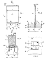
- Figures 1 and 2 first of all, we discover the illustration of a possible embodiment of the signaling device 1 of the invention which in this case comprises a base 3 surmounted in the middle part, by a vertical plate substantially rectangular 5 forming a support for a cataphot 7, for example consisting of a reflective adhesive film stuck on the plate.
- the base 3 and the plate 5 are made of molding, in a single block, based on rigid plastic material.
- the base has, in a direction substantially perpendicular to the general plane 6 of the plate, a width L1 much greater than the width L2 of this plate, thus promoting the intrinsic stability of the device.
- each rib (such as 9a) is in the form of two fins 11a, 11b arranged successively one after the other parallel to the general plane 6 of the plate 5, that is to say in fact substantially perpendicular to the direction in which the element or the work against which the device is to bear will extend, along the roadway.
- the device of the invention is capable of being installed both on one or the other of the two types of slide as on a concrete separating wall.
- the lower edge 13 of the fins 11a, 11b (which are in the form of two ship fins arranged one after the other with a part 14 in bevel; see Figure 1), so that this lower edge corresponds, at least locally, to the shape 15 of the free upper edge 15 either of one 17 ( Figure 3) or of the other 19 ( Figure 4) main existing slides.
- the lower edge of the first fin 11a has been shaped so as to be able to match locally the upper longitudinal edge of the upper bulge 20a of the first slide 17, at the location of its edge 21; while the second fin 11b has been shaped to be able to marry the second slide 19 near the upper edge 23 of its own upper bulge.
- the display device of the invention will cover the upper part of the slide considered. Maintaining it in stable equilibrium over this slide will even, preferably, be favored by the presence of a vertical wall 25 ( Figure 3) or 27 ( Figure 4) that has at its end the highest (or least projecting) ) the corresponding fin of the base 3, so that this wall comes laterally into abutment against the upper end 17a or 19a of the slide.
- blocking or fixing means which in this case consist of spring clips 29 made of elastic metal (or a similar material) which must tighten one against the other the edge 15 of the slide and the portion opposite the free edge 13 of one of the fins. These clamps will therefore be engaged at the location of the upper end 17a or 19a of the slides, over the vertical wall 25 or 27 for limiting one or the other of these fins.
- each clamp 29 may be in the form of an elastically deformable blade folded to present two solid clamping jaws. And to facilitate the opening of these jaws, their free longitudinal end will be rolled up on itself towards the outside so as to constitute substantially tubular passages 31 forming protruding edges under which a removable blade 33 can be engaged forming a lever for the spacing of the jaws for the placement of the clamps.
- the passages 31 may also have another utility. Indeed, insofar as, in general, the pliers will be used in pairs and arranged to so as to pinch the two horizontal wings 35 (see Figures 2 and 6) of the base 3, with their passages 31 arranged parallel to these wings (that is to say parallel to the direction in which the slides extend), said passages may receive (at least as regards the upper jaws of each clamp) a pin such as 37, after the latter has passed through orifices 39 formed in the plate 5 and in a lateral protuberance 41 presented by the base 3 in the upper extension of its two end ribs 9a and 9c, at the end of the wings 35.
- these may for example be crimped at the location of the protrusions 41, at the outlet of their head.
- the device of the invention has been shown in the case where it is installed in abutment by its base 3 on an upper edge 45 of a concrete wall 47.
- the display device of the invention can be installed on such a low wall, provision has been made for its positioning ribs 11a, 11b to be leveled off at the desired height so that it is possible to lay in any stability the base 3 on the upper edge 45 of the wall, the base then having, at the location of its lower edge 46, lower support zones allowing it to match the shape of the edge opposite the wall. And the previously mentioned orifices 43 will then be used for fixing the device by means of screws 49 or nails intended to be screwed or nailed with a gun (spitting) in the mass of the wall.
Landscapes
- Engineering & Computer Science (AREA)
- Architecture (AREA)
- Civil Engineering (AREA)
- Structural Engineering (AREA)
- Road Signs Or Road Markings (AREA)
- Bridges Or Land Bridges (AREA)
Claims (5)
- Vorrichtung zum Markieren für den Fahrbahnrand, mit einem Teil (5), welches eine Stütze für die Markierung bildet, die sich über ein Gestell (3) erhebt, das vorgesehen ist, auf einem Element oder Bauteil (17, 19) des Fahrbahnrandes zu ruhen, mit welchem die Vorrichtung durch Halte- oder Befestigungsmittel (29) verbunden werden kann, dadurch gekennzeichnet, daß ihr Gestell (3), damit die Vorrichtung auf unterschiedlichen Arten von Sicherheitslaufschienen (17, 19) eingebaut werden kann, eine Platte aufweist, unter welcher sich gegenüber demjenigen Teil, welches den Träger für die Markierung (5) bildet, vertikale Positionierungsrippen (9a, 9b, 9c) aus Kunststoffmaterial erstrecken, die in mehreren, untereinander im wesentlichen parallelen Linien angeordnet sind, wobei jede zwei Teile (11a, 11b) als abgefaste Flügel einer hinter dem anderen aufweist, um für ein selbes abgefastes, jeder Linie gemeinsames Teil eine freie Fasenschnittfläche (14) zu bilden, die mindestens örtlich eine Form hat, die im wesentlichen zu der einer Stützoberfläche (17a, 19a, 15) der Laufschiene komplementär ist, gegen welche das Gestell sich positionieren soll.
- Vorrichtung nach Anspruch 1, dadurch gekennzeichnet, daß die Haltemittel (29) für diese Vorrichtung auf einer Sicherheitslaufschiene elastisch deformierbare Klemmzangen (29) aufweisen, welche den oberen Längsrand (15) der Laufschiene und den Teil gegenüber dem Gestell (3), welches die Rippen trägt, umfassen.
- Vorrichtung nach Anspruch 2, dadurch gekennzeichnet, daß das freie Ende mindestens einer der Klemmzangen auf sich selbst eingerollt ist, um einen im wesentlichen rohrförmigen Durchgang zu bilden, der geeignet ist, einen Stift (37) quer durch sich selbst aufzunehmen, der dazu bestimmt ist, das in Position Halten der Vorrichtung auf der Laufschiene durch Eingriff dieses Stiftes quer durch mindestens eine Öffnung (39) sicherzustellen, die in einer Wand (41) des Gestelles (3) gebildet ist.
- Vorrichtung nach einem der vorhergehenden Ansprüche, dadurch gekennzeichnet, daß dieser Teil (5), welcher den Träger für die Markierung bildet, das Gestell (3) und die Rippen (9a, 9b, 9c) aus einem einzigen Stück aus gegossenem Plastikmaterial gebildet sind.
- Vorrichtung nach einem der vorhergehenden Ansprüche, dadurch gekennzeichnet, daß dieses Teil, welches den Träger für die Markierung bildet, sich als eine im wesentlichen ebene Platte (5) darstellt, die sich vertikal im Mittelteil der horizontalen Platte des Gestelles erhebt, wobei die Rippen paarweise in drei Linien angeordnet sind und sich jede Linie der Rippen parallel zu der Ebene (6) der Makierungsplatte erstreckt.
Applications Claiming Priority (2)
| Application Number | Priority Date | Filing Date | Title |
|---|---|---|---|
| FR8910717 | 1989-08-09 | ||
| FR8910717A FR2650845B1 (fr) | 1989-08-09 | 1989-08-09 | Dispositif de visualisation pour element ou ouvrage de bordure de chaussee |
Publications (2)
| Publication Number | Publication Date |
|---|---|
| EP0412890A1 EP0412890A1 (de) | 1991-02-13 |
| EP0412890B1 true EP0412890B1 (de) | 1993-09-15 |
Family
ID=9384605
Family Applications (1)
| Application Number | Title | Priority Date | Filing Date |
|---|---|---|---|
| EP90402241A Expired - Lifetime EP0412890B1 (de) | 1989-08-09 | 1990-08-03 | Vorrichtung zum Anzeigen von Strassenleitmittel |
Country Status (4)
| Country | Link |
|---|---|
| EP (1) | EP0412890B1 (de) |
| DE (1) | DE69003331D1 (de) |
| ES (1) | ES2043317T3 (de) |
| FR (1) | FR2650845B1 (de) |
Families Citing this family (2)
| Publication number | Priority date | Publication date | Assignee | Title |
|---|---|---|---|---|
| US6733205B2 (en) * | 2001-11-14 | 2004-05-11 | Plastic Safety Systems, Inc. | Guardrail delineators |
| DE102017115691B4 (de) * | 2017-07-12 | 2019-05-09 | Dieter Dankbar | An einer Leitplanke anbringbare Haltevorrichtung für ein Bauteil |
Family Cites Families (5)
| Publication number | Priority date | Publication date | Assignee | Title |
|---|---|---|---|---|
| DE7145792U (de) * | 1972-02-24 | Hildsberg P | Pfostenklaue für Leitplanken | |
| DE2208415A1 (de) * | 1972-02-23 | 1973-08-30 | Maibach Fa Gerd D | Befestigungseinrichtung fuer leitpfosten an leitplankenanordnungen |
| US4224002A (en) * | 1978-08-04 | 1980-09-23 | Amerace Corporation | Highway delineator |
| FR2533055B1 (fr) * | 1982-09-10 | 1985-06-28 | Marc Jean Luc | Dispositif de fixation sur des glissieres de securite routieres |
| DE3607983A1 (de) * | 1986-03-11 | 1987-09-17 | Nikolaus Bruns | Halterung fuer einen strassenleitpfosten |
-
1989
- 1989-08-09 FR FR8910717A patent/FR2650845B1/fr not_active Expired - Fee Related
-
1990
- 1990-08-03 ES ES90402241T patent/ES2043317T3/es not_active Expired - Lifetime
- 1990-08-03 DE DE90402241T patent/DE69003331D1/de not_active Expired - Lifetime
- 1990-08-03 EP EP90402241A patent/EP0412890B1/de not_active Expired - Lifetime
Also Published As
| Publication number | Publication date |
|---|---|
| FR2650845A1 (fr) | 1991-02-15 |
| ES2043317T3 (es) | 1993-12-16 |
| EP0412890A1 (de) | 1991-02-13 |
| FR2650845B1 (fr) | 1991-10-25 |
| DE69003331D1 (de) | 1993-10-21 |
Similar Documents
| Publication | Publication Date | Title |
|---|---|---|
| FR2638772A1 (fr) | Dispositif pour retenir la neige sur une toiture en tole et toiture equipee d'un tel dispositif | |
| FR2665422A1 (fr) | Montant reglable de support de corbeilles a courrier. | |
| EP0118323B1 (de) | An Fahrbahnteilern aus Beton anbringbare Vorrichtung zu deren Schutz und Sichtbarmachung | |
| FR2556932A1 (fr) | Dispositif pour empecher le stationnement des volatiles sur elements de batiments | |
| EP0823511A1 (de) | Leitplanken für Strassenverkehr | |
| FR2533055A1 (fr) | Dispositif de fixation sur des glissieres de securite routieres | |
| FR2731496A1 (fr) | Dispositif de raccordement d'angle pour conduit a corps en gouttiere et couvercle tel que moulure, plinthe ou goulotte, notamment pour appareillage electrique | |
| EP0412890A1 (de) | Vorrichtung zum Anzeigen von Strassenleitmittel | |
| FR2641304A1 (fr) | Dispositif pour eviter la pose des volatiles sur les batiments | |
| EP0899381B1 (de) | Strassenverkehrskomplex aus Bakenständer und Bakenkörper | |
| EP1566486A1 (de) | Halter für Leitplanken | |
| EP0903452A1 (de) | Verbesserte Verbindungseinrichtung von Pfosten und Paneelen | |
| EP0767276A1 (de) | Fussplatte und flexibles temporäres Verkehrsschild und dessen Verbesserungen | |
| FR2836495A1 (fr) | Dispositif de fixation de panneaux sur des glissieres de securite pour route ou autoroute | |
| FR2871482A1 (fr) | Balise de chantier a surfaces reflechissantes | |
| FR2678963A1 (fr) | Dispositif de signalisation visuelle pour voie de circulation. | |
| EP3983279A1 (de) | Verstärkungsmittel für eine vorderstruktur eines kraftfahrzeuges | |
| EP0392923A1 (de) | Palissade, zusammengestellt aus Profilelementen | |
| EP0657584B1 (de) | Befestigungsmittel für Blendschutzzaun auf Leitplanken | |
| FR2654448A1 (fr) | Dispositif de signalisation formant notamment balise routiere. | |
| EP1022833A1 (de) | Adapter für einen Mechanismussträger, und Mechanismussträger mit einem solchen Adapter, inbesondere für ein Elektrogerät | |
| EP1562165B1 (de) | Anzeigevorrichtung zur Identifizierung oder zur Bestimmung von Gebauden | |
| WO2001088275A1 (fr) | Dispositif a element signaletique autorelevant | |
| FR2612218A1 (fr) | Dispositif pour la fixation des panneaux de signalisation routiere sur les glissieres de securite | |
| FR3153102A1 (fr) | Dispositif de fixation d’un grillage sur un montant de clôture |
Legal Events
| Date | Code | Title | Description |
|---|---|---|---|
| PUAI | Public reference made under article 153(3) epc to a published international application that has entered the european phase |
Free format text: ORIGINAL CODE: 0009012 |
|
| AK | Designated contracting states |
Kind code of ref document: A1 Designated state(s): DE ES GB |
|
| 17P | Request for examination filed |
Effective date: 19910518 |
|
| 17Q | First examination report despatched |
Effective date: 19920122 |
|
| RAP1 | Party data changed (applicant data changed or rights of an application transferred) |
Owner name: ALLIBERT MANUTENTION |
|
| GRAA | (expected) grant |
Free format text: ORIGINAL CODE: 0009210 |
|
| AK | Designated contracting states |
Kind code of ref document: B1 Designated state(s): DE ES GB |
|
| PG25 | Lapsed in a contracting state [announced via postgrant information from national office to epo] |
Ref country code: GB Effective date: 19930915 Ref country code: DE Effective date: 19930915 |
|
| REF | Corresponds to: |
Ref document number: 69003331 Country of ref document: DE Date of ref document: 19931021 |
|
| GBV | Gb: ep patent (uk) treated as always having been void in accordance with gb section 77(7)/1977 [no translation filed] |
Effective date: 19930915 |
|
| PLBE | No opposition filed within time limit |
Free format text: ORIGINAL CODE: 0009261 |
|
| STAA | Information on the status of an ep patent application or granted ep patent |
Free format text: STATUS: NO OPPOSITION FILED WITHIN TIME LIMIT |
|
| 26N | No opposition filed | ||
| REG | Reference to a national code |
Ref country code: ES Ref legal event code: PC2A Owner name: ALLIBERT EQUIPEMENT (SOCIETE ANONYME) |
|
| PGFP | Annual fee paid to national office [announced via postgrant information from national office to epo] |
Ref country code: ES Payment date: 19950727 Year of fee payment: 6 |
|
| PG25 | Lapsed in a contracting state [announced via postgrant information from national office to epo] |
Ref country code: ES Free format text: LAPSE BECAUSE OF THE APPLICANT RENOUNCES Effective date: 19960805 |
|
| REG | Reference to a national code |
Ref country code: ES Ref legal event code: FD2A Effective date: 19991007 |