EP0118323B1 - An Fahrbahnteilern aus Beton anbringbare Vorrichtung zu deren Schutz und Sichtbarmachung - Google Patents
An Fahrbahnteilern aus Beton anbringbare Vorrichtung zu deren Schutz und Sichtbarmachung Download PDFInfo
- Publication number
- EP0118323B1 EP0118323B1 EP84400073A EP84400073A EP0118323B1 EP 0118323 B1 EP0118323 B1 EP 0118323B1 EP 84400073 A EP84400073 A EP 84400073A EP 84400073 A EP84400073 A EP 84400073A EP 0118323 B1 EP0118323 B1 EP 0118323B1
- Authority
- EP
- European Patent Office
- Prior art keywords
- deflector plate
- channel
- separator
- protection
- orifices
- Prior art date
- Legal status (The legal status is an assumption and is not a legal conclusion. Google has not performed a legal analysis and makes no representation as to the accuracy of the status listed.)
- Expired
Links
- 238000012800 visualization Methods 0.000 title description 5
- 230000004888 barrier function Effects 0.000 title 1
- 238000009416 shuttering Methods 0.000 claims abstract 2
- 229920000915 polyvinyl chloride Polymers 0.000 claims description 6
- 239000004800 polyvinyl chloride Substances 0.000 claims description 6
- 229920002994 synthetic fiber Polymers 0.000 claims description 5
- 229910052782 aluminium Inorganic materials 0.000 claims description 3
- XAGFODPZIPBFFR-UHFFFAOYSA-N aluminium Chemical compound [Al] XAGFODPZIPBFFR-UHFFFAOYSA-N 0.000 claims description 3
- 239000007769 metal material Substances 0.000 claims description 3
- 239000000853 adhesive Substances 0.000 claims description 2
- 230000001070 adhesive effect Effects 0.000 claims description 2
- 229910052751 metal Inorganic materials 0.000 claims description 2
- 239000002184 metal Substances 0.000 claims description 2
- 239000004411 aluminium Substances 0.000 claims 1
- 238000009415 formwork Methods 0.000 description 4
- 239000003086 colorant Substances 0.000 description 3
- XLYOFNOQVPJJNP-UHFFFAOYSA-N water Substances O XLYOFNOQVPJJNP-UHFFFAOYSA-N 0.000 description 3
- 230000001464 adherent effect Effects 0.000 description 2
- 238000001125 extrusion Methods 0.000 description 2
- 230000008595 infiltration Effects 0.000 description 2
- 238000001764 infiltration Methods 0.000 description 2
- 239000000463 material Substances 0.000 description 2
- 238000004026 adhesive bonding Methods 0.000 description 1
- 239000004020 conductor Substances 0.000 description 1
- 238000010276 construction Methods 0.000 description 1
- 230000008014 freezing Effects 0.000 description 1
- 238000007710 freezing Methods 0.000 description 1
- 238000009434 installation Methods 0.000 description 1
- 238000000034 method Methods 0.000 description 1
- 229920003023 plastic Polymers 0.000 description 1
- 239000004033 plastic Substances 0.000 description 1
Images

Classifications
-
- E—FIXED CONSTRUCTIONS
- E01—CONSTRUCTION OF ROADS, RAILWAYS, OR BRIDGES
- E01F—ADDITIONAL WORK, SUCH AS EQUIPPING ROADS OR THE CONSTRUCTION OF PLATFORMS, HELICOPTER LANDING STAGES, SIGNS, SNOW FENCES, OR THE LIKE
- E01F7/00—Devices affording protection against snow, sand drifts, side-wind effects, snowslides, avalanches or falling rocks; Anti-dazzle arrangements ; Sight-screens for roads, e.g. to mask accident site
- E01F7/06—Anti-dazzle arrangements ; Securing anti-dazzle means to crash-barriers
-
- E—FIXED CONSTRUCTIONS
- E01—CONSTRUCTION OF ROADS, RAILWAYS, OR BRIDGES
- E01F—ADDITIONAL WORK, SUCH AS EQUIPPING ROADS OR THE CONSTRUCTION OF PLATFORMS, HELICOPTER LANDING STAGES, SIGNS, SNOW FENCES, OR THE LIKE
- E01F15/00—Safety arrangements for slowing, redirecting or stopping errant vehicles, e.g. guard posts or bollards; Arrangements for reducing damage to roadside structures due to vehicular impact
- E01F15/02—Continuous barriers extending along roads or between traffic lanes
- E01F15/08—Continuous barriers extending along roads or between traffic lanes essentially made of walls or wall-like elements ; Cable-linked blocks
- E01F15/081—Continuous barriers extending along roads or between traffic lanes essentially made of walls or wall-like elements ; Cable-linked blocks characterised by the use of a specific material
- E01F15/083—Continuous barriers extending along roads or between traffic lanes essentially made of walls or wall-like elements ; Cable-linked blocks characterised by the use of a specific material using concrete
Definitions
- the invention relates to a protection and display device intended to be adapted to concrete lane separators installed on roads and motorways, separators of the type produced by machines with sliding formwork.
- Concrete separators are made without a preformed joint so that relatively anarchic cracks appear after a certain time. These cracks are relatively large every ten or fifteen meters while small cracks occur every three or four meters.
- the concrete track separator has a height from the ground of about 80 cm. This height sometimes allows the headlights of cars driving in opposite directions to be visually turned off for the driver who runs alongside the concrete lane separator. However, in most cases, these dividers are not high enough to obscure the lights of the headlights of oncoming cars.
- the anti-dazzle systems currently produced are very expensive and are dangerous because they are liable to break. These devices consist in particular of nets stretched over metal supports or of vertical blades placed and sealed on the upper part of the concrete track separators.
- the object of the present invention is to remedy these drawbacks and proposes to create a protection and display device intended to be adapted to concrete track separators, of a relatively low cost price, of easy assembly and allowing not only the protection of cracks in the concrete lane separator, but also a better materialization of the upper line of the concrete lane separator, hence greater safety for the motorist.
- the present invention aims to create a protection device and visualization of concrete lane dividers to obscure the lights of cars traveling in opposite directions.
- the invention relates to a protection and display device intended to be adapted to concrete lane dividers installed on the highway to highway separators of the type produced by machines with sliding formwork, device characterized in that it consists of at least one protection and display gutter fitting onto the upper part of the separator, the section profile of the gutter being of shape corresponding to the shape of the upper edge of the concrete channel separator.
- the gutter helps protect small cracks that occur in the concrete lane separator against water infiltration, and therefore against frost in winter.
- this gutter generally of various colors, makes it possible to materialize the upper line of the separator.
- the gutter has a general shape of U.
- the gutter is fixed to the concrete track separator by gluing, this results in very great ease of assembly.
- the sides of the gutter serve as supports for reflective strips of light.
- the gutter is surmounted by a parallelepipedal deflecting plate, one of the longitudinal fields of the plate being arranged in the extension of the vertical median axis of the channel separator.
- the deflector plate in particular makes it possible to sufficiently close the lights of vehicles traveling in opposite directions, thus avoiding blinding motorists.
- the deflector plate is provided with stiffening ribs.
- the deflector plate is provided with orifices of circular or polygonal shape.
- the orifices of the deflector plate are staggered.
- the orifices of the deflector plate are slots.
- the orifices and slots provided in the deflector plate allow better resistance by letting air and debris carried by the wind pass.
- the orifices of the deflector plate are determined by blades in the form of louvers.
- At least one of the ends of the device is provided with cutouts for the fixing by overlapping of two successive gutters.
- the gutter and the deflector plate form a modular monobloc assembly.
- each modular monobloc element is made of a synthetic material such as polyvinyl chloride.
- each modular monobloc element is made of a metallic material such as aluminum or galvanized sheet.
- the deflector plate is colored.
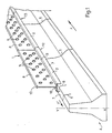
- the protection and display device 1 consists of a gutter 2.
- the p _ wire of this gutter, seen in section, is of forma corresponding to the shape of the upper edge 3 of the separator concrete tracks 4.
- the concrete track separator is of the type designated by the expression (DBA) meaning double adherent concrete.
- the channel separator in. Concrete 4 is produced using a sliding formwork machine. Such a separator is made without a preformed joint so that after a certain time large cracks appear 5 approximately every ten or fifteen meters, while in the upper part 3, small cracks occur.
- gutter in general U shape fits on the upper edge 3 of the separator 4. It protects the separator 4 against water infiltration in the cracks 5, 6 and, consequently, against freezing.
- the gutter 2 is fixed to the edge 3 by bonding points.
- the sides 7 of the gutter 2 serve as supports for reflective strips of light. This allows the meterization of the upper line of track separator 4.
- the gutter 2, according to this embodiment, is made of a material such as polyvinyl chloride which is an inexpensive plastic material.
- the gutter 2 is produced by extrusion and can be produced in different colors. In principle, the chosen color is white, but it is also possible to color the gutters in green and red or to alternate these different colors depending on demand.
- the gutter 2 better materializes the upper line of the lane separator 4, the vehicles traveling on lanes in the opposite direction according to the arrows F and F ′,
- the gutter 2 is surmounted by a deflecting plate 8.
- This deflecting plate is of generally parallelepipedal shape, one of the fields 9 of the plate 8 being arranged in the extension of the vertical median axis XY of the channel separator 4.
- the deflector plate 8 is produced from a sheet of synthetic material such as polyvinyl chloride.
- the deflector plate 8 is provided with stiffening ribs 10 resulting from the extrusion.
- the deflector plate 8 is provided with circular orifices 11 staggered. It is possible to provide orifices of shapes other than circular, such as for example polygonal orifices or slots etc. The arrangement of these orifices is also left to the choice of the request. The orifices are intended in particular to allow air and debris entrained by the wind to pass, which makes it possible to obtain better resistance and less rapid wear.
- the deflector plates 8 sufficiently close the lights of vehicles traveling in the opposite direction so as to avoid the driver from being dazzled or blinded. Indeed, in this case, the only vision of the lights that remains for the driver is a blinding or lateral vision.
- the height of the deflector plates 8 is chosen according to the nature of the terrain where the concrete track separator is installed.
- the gutter 2 and the deflector plate 8 form a modular monobloc element the length of which can be one, two or three meters, so as to facilitate transport and installation, while making it possible to follow the turns or the deformations of the profiles. in lông.
- Each modular monobloc element 12, 13 each formed by a gutter 2 surmounted by a deflector plate 8, is provided at one of its ends with specific cutouts not shown in this figure for the fixing by overlapping of two successive gutters 2 or of two successive modular monoblock elements 12, 13.
- the overlapping of a first element 12 on the second element 13 is carried out in the direction of descent so that water cannot penetrate between two successive elements 12, 13.
- Each modular monobloc element 12, 13 is made of a synthetic material such as polyvinyl chloride. It is also possible to provide for an embodiment of the one-piece elements modular 12, 13 made of a metallic material such as aluminum or galvanized sheet.
- the modular monobloc element 14 constitutes a second embodiment. It is formed by a gutter 2 of general U-shaped profile, this gutter 2 being surmounted by a deflector plate 8.
- the deflector plate 8 comprises orifices constituted by blades 15 deformed when hot when it is polyvinyl chloride.
- the blades 15 are in the form of louvers and allow the passage of air and debris carried by the wind, while avoiding the dazzling of conductors by the lights of vehicles traveling in the opposite direction.
- the modular monobloc element 16 is a third embodiment. It is formed of a U-shaped gutter 2 surmounted by a deflecting plate 8.
- the deflecting plate 8 is provided with cutouts of polygonal shape 17, these cutouts being staggered. It is of course possible to provide other arrangements of the orifices while obtaining the same objects as those sought by the present invention.
Landscapes
- Engineering & Computer Science (AREA)
- Architecture (AREA)
- Civil Engineering (AREA)
- Structural Engineering (AREA)
- Road Signs Or Road Markings (AREA)
- Sewage (AREA)
- Discharge-Lamp Control Circuits And Pulse- Feed Circuits (AREA)
- Bidet-Like Cleaning Device And Other Flush Toilet Accessories (AREA)
- Investigating Materials By The Use Of Optical Means Adapted For Particular Applications (AREA)
- Bridges Or Land Bridges (AREA)
- Refuge Islands, Traffic Blockers, Or Guard Fence (AREA)
- Road Paving Structures (AREA)
Claims (15)
Priority Applications (1)
| Application Number | Priority Date | Filing Date | Title |
|---|---|---|---|
| AT84400073T ATE20928T1 (de) | 1983-02-04 | 1984-01-13 | An fahrbahnteilern aus beton anbringbare vorrichtung zu deren schutz und sichtbarmachung. |
Applications Claiming Priority (2)
| Application Number | Priority Date | Filing Date | Title |
|---|---|---|---|
| FR8301798A FR2540533B1 (fr) | 1983-02-04 | 1983-02-04 | Dispositif de protection et de visualisation destine a etre adapte sur des separateurs de voies en beton |
| FR8301798 | 1983-02-04 |
Publications (2)
| Publication Number | Publication Date |
|---|---|
| EP0118323A1 EP0118323A1 (de) | 1984-09-12 |
| EP0118323B1 true EP0118323B1 (de) | 1986-07-23 |
Family
ID=9285619
Family Applications (1)
| Application Number | Title | Priority Date | Filing Date |
|---|---|---|---|
| EP84400073A Expired EP0118323B1 (de) | 1983-02-04 | 1984-01-13 | An Fahrbahnteilern aus Beton anbringbare Vorrichtung zu deren Schutz und Sichtbarmachung |
Country Status (4)
| Country | Link |
|---|---|
| EP (1) | EP0118323B1 (de) |
| AT (1) | ATE20928T1 (de) |
| DE (1) | DE3460305D1 (de) |
| FR (1) | FR2540533B1 (de) |
Cited By (1)
| Publication number | Priority date | Publication date | Assignee | Title |
|---|---|---|---|---|
| DE8712157U1 (de) * | 1987-09-08 | 1987-10-29 | Techno-Polymer Hans-J. Kuhl, 5982 Neuenrade | Blendschutzbake |
Families Citing this family (16)
| Publication number | Priority date | Publication date | Assignee | Title |
|---|---|---|---|---|
| FR2610650B1 (fr) * | 1987-02-11 | 1989-10-27 | Allibert Sa | Ecran antieblouissant |
| US4751893A (en) * | 1987-03-20 | 1988-06-21 | Brantley William S | Anti-glare screen |
| FR2615540B1 (fr) * | 1987-05-18 | 1989-08-18 | Weiss Claude | Dispositif de signalisation pour organe de protection routier tel que rails de securite ou murs |
| FR2619400B1 (fr) * | 1987-08-14 | 1991-08-16 | Sodirel Diffusion Rgle Locale | Glissieres temporaires de securite et de signalisation et caissons pour la construction de celles-ci |
| FR2621622B1 (fr) * | 1987-10-07 | 1991-07-26 | Masair | Ecran anti-eblouissement |
| FR2638470B1 (fr) * | 1988-10-27 | 1992-02-21 | Clerempuy Georges | Rideau de securite de fluidite du trafic routier |
| FR2662720B1 (fr) * | 1990-06-05 | 1993-01-29 | Sodilor Sa | Dispositif antieblouissant pour glissiere de securite routiere. |
| US5149061A (en) * | 1991-08-27 | 1992-09-22 | Arsenio Borgnini | Panel for road construction |
| DE59403316D1 (de) * | 1993-03-19 | 1997-08-14 | Wilhelm Junker | Leiteinrichtung für leitwände |
| FR2737524B1 (fr) * | 1995-08-02 | 1997-11-07 | Sbr Soc | Poteau de support et element de cloture le comportant |
| US6149338A (en) * | 1998-07-20 | 2000-11-21 | Anderson; John Derrick | Highway barrier |
| NL1014940C2 (nl) * | 2000-04-13 | 2001-10-16 | Marcel Peter Gort | Wegmarkeringsamenstel voor het markeren van bijzondere situaties langs een weg. |
| GB2373806B (en) * | 2001-03-31 | 2005-04-27 | Hill & Smith Ltd | Safety barriers |
| CN106592453B (zh) * | 2016-12-29 | 2022-06-24 | 范瑶飞 | 一种多用途市政道路隔离带 |
| CN111236114B (zh) * | 2020-01-08 | 2021-11-19 | 杜祥成 | 预制装配式市政工程隔离带 |
| CN112942156A (zh) * | 2021-01-27 | 2021-06-11 | 李兰普 | 防眩格板 |
Family Cites Families (20)
| Publication number | Priority date | Publication date | Assignee | Title |
|---|---|---|---|---|
| US2135400A (en) * | 1937-11-04 | 1938-11-01 | Joseph O Johnson | Highway guard |
| US2233308A (en) * | 1940-09-16 | 1941-02-25 | Stillwater Clay Products Compa | Flanged wall coping |
| DE1459802A1 (de) * | 1963-07-03 | 1968-11-21 | Bochumer Eisen Heintzmann | Leitband fuer Fahrbahnseiten,insbesondere fuer Kraftverkehrsstrassen |
| CH402914A (de) * | 1963-09-19 | 1965-11-30 | Schrepfer Richard | Schutzvorrichtung für Kraftfahrzeuge |
| BE680811A (de) * | 1965-05-10 | 1966-11-10 | ||
| FR1447844A (fr) * | 1965-09-27 | 1966-07-29 | Eisen & Metall Ag | Dispositif anti-éblouissant pour voies de communication |
| GB1180965A (en) * | 1967-06-12 | 1970-02-11 | P J P Trading Ltd | An Improved Coping for External Walls. |
| DE1658678A1 (de) * | 1967-09-16 | 1970-11-05 | Meyer Geb Wagner Hanna | Blendschutzzaun fuer gegenlaeufige Fahrbahnen,insbesondere Autobahnen |
| DE1980756U (de) * | 1967-09-29 | 1968-03-14 | Eisen & Metall Ag | Halteschaft fuer blendenschutzelemente von lichtzaeunen an autobahnen. |
| GB1209646A (en) * | 1967-11-15 | 1970-10-21 | Sugiaki Kusatake | A roadway boundary block |
| FR2171645A8 (de) * | 1972-02-10 | 1973-09-21 | Lebas Robert | |
| DE2515938A1 (de) * | 1975-04-11 | 1976-10-21 | Josef Dreker | Reflektoranordnung fuer begrenzungen |
| FR2416303A1 (fr) * | 1978-02-02 | 1979-08-31 | Fornells Sa | Elements de signalisation destines aux glissieres metalliques de securite routiere |
| DE2821349A1 (de) * | 1978-05-16 | 1979-11-22 | Rolf Von Maurich | Sicherheitsblendschutzzaun insbesondere fuer autobahnen |
| US4222552A (en) * | 1978-10-20 | 1980-09-16 | Matteo Sr George W | Highway guardrail cover |
| DE7833639U1 (de) * | 1978-11-11 | 1979-02-22 | Silbernagel, Hermann, 6800 Mannheim | Schilderstaender |
| US4249832A (en) * | 1978-12-13 | 1981-02-10 | High Performance Composites, Inc. | Highway median delineator |
| DE2917953A1 (de) * | 1979-05-04 | 1980-11-13 | Ferch & Nabben | Leitbalken fuer den strassenverkehr |
| CA1141574A (en) * | 1980-04-25 | 1983-02-22 | Peter F. Trent | Median barrier construction |
| US4338041A (en) * | 1981-01-12 | 1982-07-06 | Schmanski Donald W | Glarefoil assembly |
-
1983
- 1983-02-04 FR FR8301798A patent/FR2540533B1/fr not_active Expired
-
1984
- 1984-01-13 AT AT84400073T patent/ATE20928T1/de not_active IP Right Cessation
- 1984-01-13 DE DE8484400073T patent/DE3460305D1/de not_active Expired
- 1984-01-13 EP EP84400073A patent/EP0118323B1/de not_active Expired
Cited By (1)
| Publication number | Priority date | Publication date | Assignee | Title |
|---|---|---|---|---|
| DE8712157U1 (de) * | 1987-09-08 | 1987-10-29 | Techno-Polymer Hans-J. Kuhl, 5982 Neuenrade | Blendschutzbake |
Also Published As
| Publication number | Publication date |
|---|---|
| FR2540533B1 (fr) | 1987-08-14 |
| ATE20928T1 (de) | 1986-08-15 |
| EP0118323A1 (de) | 1984-09-12 |
| FR2540533A1 (fr) | 1984-08-10 |
| DE3460305D1 (en) | 1986-08-28 |
Similar Documents
| Publication | Publication Date | Title |
|---|---|---|
| EP0118323A1 (de) | An Fahrbahnteilern aus Beton anbringbare Vorrichtung zu deren Schutz und Sichtbarmachung | |
| US4575278A (en) | Rain draining lane marker | |
| US4751893A (en) | Anti-glare screen | |
| US6190085B1 (en) | Railing | |
| FR2573105A1 (fr) | Glissiere de securite. | |
| EP0452205A2 (de) | Leitplankenanlage mit zwei Leitplanken zum Zurückhalten von Fahrzeugen auf ihren eigenen Fahrbahn | |
| FR2619400A1 (fr) | Glissieres temporaires de securite et de signalisation et caissons pour la construction de celles-ci | |
| FR2551784A3 (fr) | Paroi d'isolation phonique | |
| EP1566486A1 (de) | Halter für Leitplanken | |
| EP0479693B1 (de) | Strassenbeleuchtungsverfahren und -vorrichtung mit horizontalem, auf die Rückseite der Fahrzeuge gerichtetem Lichtstrom | |
| KR0131498Y1 (ko) | 도로 표지병 | |
| FR2841915A1 (fr) | Pave en beton autobloquant | |
| EP0544586A1 (de) | Reflektierender Schutzüberzug für Leitplanken | |
| FR2678963A1 (fr) | Dispositif de signalisation visuelle pour voie de circulation. | |
| FR2665465A1 (fr) | Dispositif de prevention pour la circulation routiere. | |
| FR2613393A1 (fr) | Bordure de marquage et/ou de balisage pour l'amenagement des routes | |
| KR100710877B1 (ko) | 유턴차선 표시용 완충식 도로 표지병 | |
| EP0412890B1 (de) | Vorrichtung zum Anzeigen von Strassenleitmittel | |
| FR2610650A1 (fr) | Ecran antieblouissant | |
| KR200366987Y1 (ko) | 경사각이 조정 가능한 도로 이정표 | |
| FR2726588A1 (fr) | Bandes de dissuasion de stationnement abusif sur les trottoirs | |
| EP0657584B1 (de) | Befestigungsmittel für Blendschutzzaun auf Leitplanken | |
| FR2686104A1 (fr) | Dispositif lumineux de securite et de signalisation pour voies de circulation. | |
| EP1550771B1 (de) | Leuchtsignalanordnung für Stadt- oder Routenkreuzung | |
| FR2637851A1 (fr) | Dispositif anti-eblouissement embarque pour conducteur de vehicule automobile |
Legal Events
| Date | Code | Title | Description |
|---|---|---|---|
| PUAI | Public reference made under article 153(3) epc to a published international application that has entered the european phase |
Free format text: ORIGINAL CODE: 0009012 |
|
| AK | Designated contracting states |
Kind code of ref document: A1 Designated state(s): AT BE CH DE IT LI LU NL SE |
|
| 17P | Request for examination filed |
Effective date: 19841129 |
|
| GRAA | (expected) grant |
Free format text: ORIGINAL CODE: 0009210 |
|
| AK | Designated contracting states |
Kind code of ref document: B1 Designated state(s): AT BE CH DE IT LI LU NL SE |
|
| PG25 | Lapsed in a contracting state [announced via postgrant information from national office to epo] |
Ref country code: NL Effective date: 19860723 Ref country code: IT Free format text: LAPSE BECAUSE OF FAILURE TO SUBMIT A TRANSLATION OF THE DESCRIPTION OR TO PAY THE FEE WITHIN THE PRESCRIBED TIME-LIMIT;WARNING: LAPSES OF ITALIAN PATENTS WITH EFFECTIVE DATE BEFORE 2007 MAY HAVE OCCURRED AT ANY TIME BEFORE 2007. THE CORRECT EFFECTIVE DATE MAY BE DIFFERENT FROM THE ONE RECORDED. Effective date: 19860723 Ref country code: AT Effective date: 19860723 |
|
| REF | Corresponds to: |
Ref document number: 20928 Country of ref document: AT Date of ref document: 19860815 Kind code of ref document: T |
|
| PG25 | Lapsed in a contracting state [announced via postgrant information from national office to epo] |
Ref country code: SE Effective date: 19860731 |
|
| REF | Corresponds to: |
Ref document number: 3460305 Country of ref document: DE Date of ref document: 19860828 |
|
| NLV1 | Nl: lapsed or annulled due to failure to fulfill the requirements of art. 29p and 29m of the patents act | ||
| PG25 | Lapsed in a contracting state [announced via postgrant information from national office to epo] |
Ref country code: LU Free format text: LAPSE BECAUSE OF NON-PAYMENT OF DUE FEES Effective date: 19870131 Ref country code: LI Effective date: 19870131 Ref country code: CH Effective date: 19870131 |
|
| PLBE | No opposition filed within time limit |
Free format text: ORIGINAL CODE: 0009261 |
|
| STAA | Information on the status of an ep patent application or granted ep patent |
Free format text: STATUS: NO OPPOSITION FILED WITHIN TIME LIMIT |
|
| 26N | No opposition filed | ||
| BERE | Be: lapsed |
Owner name: MATERIELS ET APPLICATIONS DE SECURITE POUR LES AER Effective date: 19870131 |
|
| REG | Reference to a national code |
Ref country code: CH Ref legal event code: PL |
|
| PG25 | Lapsed in a contracting state [announced via postgrant information from national office to epo] |
Ref country code: DE Effective date: 19871001 |
|
| PG25 | Lapsed in a contracting state [announced via postgrant information from national office to epo] |
Ref country code: BE Effective date: 19890131 |