EP0413086A1 - Transducteur électro-acoustique - Google Patents
Transducteur électro-acoustique Download PDFInfo
- Publication number
- EP0413086A1 EP0413086A1 EP90107295A EP90107295A EP0413086A1 EP 0413086 A1 EP0413086 A1 EP 0413086A1 EP 90107295 A EP90107295 A EP 90107295A EP 90107295 A EP90107295 A EP 90107295A EP 0413086 A1 EP0413086 A1 EP 0413086A1
- Authority
- EP
- European Patent Office
- Prior art keywords
- plate
- electroacoustic transducer
- transducer according
- membrane
- sound
- Prior art date
- Legal status (The legal status is an assumption and is not a legal conclusion. Google has not performed a legal analysis and makes no representation as to the accuracy of the status listed.)
- Granted
Links
Images

Classifications
-
- H—ELECTRICITY
- H04—ELECTRIC COMMUNICATION TECHNIQUE
- H04R—LOUDSPEAKERS, MICROPHONES, GRAMOPHONE PICK-UPS OR LIKE ACOUSTIC ELECTROMECHANICAL TRANSDUCERS; ELECTRIC HEARING AIDS; PUBLIC ADDRESS SYSTEMS
- H04R1/00—Details of transducers, loudspeakers or microphones
- H04R1/20—Arrangements for obtaining desired frequency or directional characteristics
- H04R1/32—Arrangements for obtaining desired frequency or directional characteristics for obtaining desired directional characteristic only
- H04R1/34—Arrangements for obtaining desired frequency or directional characteristics for obtaining desired directional characteristic only by using a single transducer with sound reflecting, diffracting, directing or guiding means
- H04R1/342—Arrangements for obtaining desired frequency or directional characteristics for obtaining desired directional characteristic only by using a single transducer with sound reflecting, diffracting, directing or guiding means for microphones
-
- H—ELECTRICITY
- H04—ELECTRIC COMMUNICATION TECHNIQUE
- H04R—LOUDSPEAKERS, MICROPHONES, GRAMOPHONE PICK-UPS OR LIKE ACOUSTIC ELECTROMECHANICAL TRANSDUCERS; ELECTRIC HEARING AIDS; PUBLIC ADDRESS SYSTEMS
- H04R1/00—Details of transducers, loudspeakers or microphones
- H04R1/20—Arrangements for obtaining desired frequency or directional characteristics
- H04R1/22—Arrangements for obtaining desired frequency or directional characteristics for obtaining desired frequency characteristic only
- H04R1/222—Arrangements for obtaining desired frequency or directional characteristics for obtaining desired frequency characteristic only for microphones
Definitions
- the invention relates to an electroacoustic transducer according to the preamble of claim 1.
- Such a transducer is known from the magazine "Funkschau", issue 16, 1985, pages 43-45.
- the reverberant plates used in known interface microphones are either circular, square or rectangular.
- the transducer element is usually attached centrally.
- the edge of the panel usually has a phase of approximately 45 °, while in the case of thin panels, the edge is usually only broken.
- the plate is irregularly rounded or flattened towards the edge.
- This phase jump is different depending on the nature of the edges and the impedance of the surfaces of the microphone body and the interface.
- the creeping wave thus generates a more or less complicated interference pattern.
- the superimposition of the incident wave with the creeping wave at the installation location of the transducer is decisive. Negative effects on the frequency response and the directional characteristic can only be avoided if creeping waves are either completely avoided or if they have an overall frequency-independent phase position and a frequency-independent level at the installation location of the converter.
- the creeping wave can only be avoided if the mounting plate were infinitely thin or extended infinitely. A thickness of 1 to 2 mm, which in practice would be sufficient to avoid creeping waves, is not technically feasible, since no electrostatic converter is available for installation in such a thin mounting plate.
- the object of the invention is to achieve a frequency-independent, hemispherical directional characteristic with a high sound fidelity in an electrostatic converter of the type mentioned at the beginning.
- the electroacoustic transducer according to the invention is optimized with regard to the geometric shape of its mounting plate and its mounting position in the mounting plate so that creeping waves at the installation location of the transducer have an overall frequency-independent phase position and a frequency-independent level. For every angle of incidence, it is thus ensured that the superposition of the incident wave with the secondary sound field at the transducer location that is caused by diffraction on the microphone plate there is no linear influence on the frequency response.
- the path lengths from each edge point of the plate to the membrane center are preferably distributed uniformly in a length range, the upper limit of which is determined by the sound wavelength of the upper limit frequency of the electroacoustic transducer and the lower limit of which is determined by half the sound wavelength of the transition frequency at which a sound pressure jam begins to form in front of the microphone area.
- the plate is designed as an oblique-angled triangle.
- the embodiment of an electroacoustic transducer according to the invention shown in plan view in FIG. 1 and in section in FIG. 2 has a triangular support plate P with the side edges or triangular legs a, b and c.
- a transducer capsule W is recessed so that the membrane M of the transducer capsule W is flush with the surface of the plate P facing the incident sound.
- the exact location of the transducer capsule W in the example shown is on the line of gravity s1 between its base point F and the center of gravity S.
- the transducer capsule W is connected through the plate with a microphone cable K, which installs at the base of the line of gravity s2 or the shortest leg b and ends in a cable connector St at its other end.
- the section according to FIG. 2 shows the flush installation of the membrane M and the mounting of the transducer capsule W in a recess in the mounting plate P.
- the transducer W can preferably be an electrostatic transducer or a pressure-calibrated transducer, i.e. a transducer that outputs a constant voltage in the listening area at constant sound pressure.
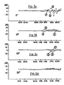
- the frequency response of the electroacoustic transducer W according to FIGS. 1 and 2 were measured at different sound incidence angles of 0 °, 30 °, 60 ° and 90 ° based on the level of the mounting plate P.
- the results are in the figures 3a to 3d shown using the solid curve # 1.
- the corresponding frequency responses of known interface microphones with a rectangular carrier plate (dashed curve # 2) and a circular carrier plate (curve # 3) are shown in FIGS. 3a to 3d drawn.
- the flat frequency response achieved with the transducer according to the invention at all sound incidence angles ideally means a frequency-independent, hemispherical directional characteristic. Direct sound and diffuse sound do not result in different sound colors, such as occur with a transducer in the free sound field due to the diffraction and shadowing effects on the microphone body.
- the surface-flush installation of the transducer in the plate avoids sound colorations, such as occur in conventional microphones due to delayed reflections at the space boundary surfaces and the associated comb filter effect.
Landscapes
- Health & Medical Sciences (AREA)
- Otolaryngology (AREA)
- Physics & Mathematics (AREA)
- Engineering & Computer Science (AREA)
- Acoustics & Sound (AREA)
- Signal Processing (AREA)
- Electrostatic, Electromagnetic, Magneto- Strictive, And Variable-Resistance Transducers (AREA)
- Diaphragms For Electromechanical Transducers (AREA)
- Obtaining Desirable Characteristics In Audible-Bandwidth Transducers (AREA)
- Measuring Fluid Pressure (AREA)
- Details Of Audible-Bandwidth Transducers (AREA)
- Piezo-Electric Transducers For Audible Bands (AREA)
Applications Claiming Priority (2)
| Application Number | Priority Date | Filing Date | Title |
|---|---|---|---|
| DE3926884 | 1989-08-16 | ||
| DE3926884A DE3926884A1 (de) | 1989-08-16 | 1989-08-16 | Elektroakustischer wandler |
Publications (2)
| Publication Number | Publication Date |
|---|---|
| EP0413086A1 true EP0413086A1 (fr) | 1991-02-20 |
| EP0413086B1 EP0413086B1 (fr) | 1994-06-01 |
Family
ID=6387125
Family Applications (1)
| Application Number | Title | Priority Date | Filing Date |
|---|---|---|---|
| EP90107295A Expired - Lifetime EP0413086B1 (fr) | 1989-08-16 | 1990-04-18 | Transducteur électro-acoustique |
Country Status (5)
| Country | Link |
|---|---|
| US (1) | US5168525A (fr) |
| EP (1) | EP0413086B1 (fr) |
| JP (1) | JPH0388599A (fr) |
| AT (1) | ATE106650T1 (fr) |
| DE (2) | DE3926884A1 (fr) |
Families Citing this family (22)
| Publication number | Priority date | Publication date | Assignee | Title |
|---|---|---|---|---|
| USD352039S (en) | 1992-05-19 | 1994-11-01 | Sun Microsystems, Inc. | Microphone for computer |
| US5574794A (en) * | 1995-01-19 | 1996-11-12 | Earmark, Inc. | Microphone assembly for adhesive attachment to a vibratory surface |
| US6421444B1 (en) * | 1995-09-28 | 2002-07-16 | Nortel Networks Limited | Embedded higher order microphone |
| US5684756A (en) * | 1996-01-22 | 1997-11-04 | The United States Of America As Represented By The Administrator Of The National Aeronautics And Space Administration | Noise reducing screen devices for in-flow pressure sensors |
| DE19703311A1 (de) * | 1997-01-30 | 1998-08-06 | Sennheiser Electronic | Grenzflächenmikrofon |
| US7349546B2 (en) * | 2003-09-04 | 2008-03-25 | Kyocera Wireless Corp. | System and method for identifying a headset type in an electrical device |
| US7106875B2 (en) * | 2003-09-09 | 2006-09-12 | King James T | Dual boundary pressure zone three dimensional microphone and hearing aid |
| US20060132595A1 (en) * | 2004-10-15 | 2006-06-22 | Kenoyer Michael L | Speakerphone supporting video and audio features |
| US7720232B2 (en) * | 2004-10-15 | 2010-05-18 | Lifesize Communications, Inc. | Speakerphone |
| US7903137B2 (en) * | 2004-10-15 | 2011-03-08 | Lifesize Communications, Inc. | Videoconferencing echo cancellers |
| US7970151B2 (en) * | 2004-10-15 | 2011-06-28 | Lifesize Communications, Inc. | Hybrid beamforming |
| US7720236B2 (en) * | 2004-10-15 | 2010-05-18 | Lifesize Communications, Inc. | Updating modeling information based on offline calibration experiments |
| US7760887B2 (en) * | 2004-10-15 | 2010-07-20 | Lifesize Communications, Inc. | Updating modeling information based on online data gathering |
| US8116500B2 (en) * | 2004-10-15 | 2012-02-14 | Lifesize Communications, Inc. | Microphone orientation and size in a speakerphone |
| US7826624B2 (en) * | 2004-10-15 | 2010-11-02 | Lifesize Communications, Inc. | Speakerphone self calibration and beam forming |
| US7991167B2 (en) * | 2005-04-29 | 2011-08-02 | Lifesize Communications, Inc. | Forming beams with nulls directed at noise sources |
| US7970150B2 (en) * | 2005-04-29 | 2011-06-28 | Lifesize Communications, Inc. | Tracking talkers using virtual broadside scan and directed beams |
| US7593539B2 (en) * | 2005-04-29 | 2009-09-22 | Lifesize Communications, Inc. | Microphone and speaker arrangement in speakerphone |
| DE202009015757U1 (de) | 2009-11-17 | 2010-09-23 | Maier, Andreas | Mikrofon-Halterung |
| JP5708629B2 (ja) * | 2012-02-21 | 2015-04-30 | ヤマハ株式会社 | マイクロホン装置 |
| US10419850B2 (en) | 2017-01-18 | 2019-09-17 | Trident Acoustics | Dynamic boundary pressure zone microphone |
| FI20175954A1 (fi) * | 2017-10-27 | 2019-04-28 | Teknologian Tutkimuskeskus Vtt Oy | Kotelo melumittaria varten ja melumittari |
Citations (1)
| Publication number | Priority date | Publication date | Assignee | Title |
|---|---|---|---|---|
| DE3334945A1 (de) * | 1982-09-27 | 1984-04-05 | Sony Corp., Tokio/Tokyo | Mikrofonanordnung |
Family Cites Families (7)
| Publication number | Priority date | Publication date | Assignee | Title |
|---|---|---|---|---|
| FR2394221A1 (fr) * | 1977-06-10 | 1979-01-05 | Thomson Csf | Dispositif transducteur electro-acoustique reversible a caracteristique de directivite constante dans une large bande de frequences |
| JPS5859697A (ja) * | 1981-10-05 | 1983-04-08 | Matsushita Electric Ind Co Ltd | 平板スピ−カ |
| SE443483B (sv) * | 1983-01-14 | 1986-02-24 | Gustav Georg Arne Bolin | Mottagardon for ljudvagor bestaende av en resonansskiva och en for dennas av ljudvagorna framkallade svengningar reagerande piezoelektrisk mikrofon av kristalltyp |
| DE3331657A1 (de) * | 1983-09-02 | 1985-03-21 | Canton Elektronik GmbH & Co, 6395 Weilrod | Lautsprecher |
| JPS60244190A (ja) * | 1984-05-17 | 1985-12-04 | Matsushita Electric Ind Co Ltd | 角形平面スピ−カ |
| JPS6124399A (ja) * | 1984-07-12 | 1986-02-03 | Onkyo Corp | N角形平板型振動板 |
| US4742548A (en) * | 1984-12-20 | 1988-05-03 | American Telephone And Telegraph Company | Unidirectional second order gradient microphone |
-
1989
- 1989-08-16 DE DE3926884A patent/DE3926884A1/de active Granted
-
1990
- 1990-04-18 DE DE59005896T patent/DE59005896D1/de not_active Expired - Fee Related
- 1990-04-18 AT AT90107295T patent/ATE106650T1/de not_active IP Right Cessation
- 1990-04-18 EP EP90107295A patent/EP0413086B1/fr not_active Expired - Lifetime
- 1990-08-13 JP JP2214895A patent/JPH0388599A/ja active Pending
- 1990-08-15 US US07/567,572 patent/US5168525A/en not_active Expired - Fee Related
Patent Citations (1)
| Publication number | Priority date | Publication date | Assignee | Title |
|---|---|---|---|---|
| DE3334945A1 (de) * | 1982-09-27 | 1984-04-05 | Sony Corp., Tokio/Tokyo | Mikrofonanordnung |
Also Published As
| Publication number | Publication date |
|---|---|
| US5168525A (en) | 1992-12-01 |
| ATE106650T1 (de) | 1994-06-15 |
| DE3926884C2 (fr) | 1991-11-28 |
| EP0413086B1 (fr) | 1994-06-01 |
| JPH0388599A (ja) | 1991-04-12 |
| DE3926884A1 (de) | 1991-02-21 |
| DE59005896D1 (de) | 1994-07-07 |
Similar Documents
| Publication | Publication Date | Title |
|---|---|---|
| EP0413086B1 (fr) | Transducteur électro-acoustique | |
| DE69635308T2 (de) | Piezoelektrischer wandler | |
| DE3855887T2 (de) | Stereophonisches Schallabgabesystem mit kontrollierter Richtwirkungscharakteristik | |
| DE2749987C3 (de) | Elektrostatischer Schallwandler | |
| DE3023291A1 (de) | Akustisches filter fuer ein koaxiales lautsprechersystem | |
| DE3587217T2 (de) | Gradientmikrophon zweiter ordnung mit einseitiger richtcharakteristik. | |
| DE3046416C2 (de) | Akustischer Wandler mit einer Vielzahl von Mikrohonelementpaaren | |
| DE69803933T2 (de) | Verfahren zur elektronischen strahlformung von akustischen signalen und akustisches sensorgerät | |
| DE68920031T2 (de) | Audiotransducer mit regelbarem flexibilitätsdiaphragma. | |
| DE2150194A1 (de) | Elektroakustischer Wandler | |
| DE69506131T2 (de) | Akustischer richtwandler | |
| DE2330367A1 (de) | Elektrostatischer wandler | |
| DE2343818C3 (de) | Kopfhörer | |
| DE3004917A1 (de) | Kopfhoerer | |
| DE2400625A1 (de) | Elektroakustischer wandler | |
| DE3008638A1 (de) | Kondensatormikrophon | |
| DE3839702A1 (de) | Vorrichtung zur stereofonen, elektroakustischen signalwandlung | |
| DE3708422C2 (de) | Stereo-Lautsprechersystem | |
| DE3242578A1 (de) | Elektretwandler mit veraenderlichem tatsaechlichem luftspalt | |
| DE3637910A1 (de) | Lautsprechergehaeuse | |
| EP0193886A2 (fr) | Membrane pour haut-parleur plan | |
| DE69326708T2 (de) | Lautsprechereinrichtung mit mehreren Lautsprechereinheiten zur Kontrolle der Richtcharakteristik | |
| DE3242554A1 (de) | Elektretwandler mit veraenderlicher elektretfoliendicke | |
| DE1121116B (de) | Kondensatormikrophon | |
| DE3334945C2 (de) | Mikrofonanordnung |
Legal Events
| Date | Code | Title | Description |
|---|---|---|---|
| PUAI | Public reference made under article 153(3) epc to a published international application that has entered the european phase |
Free format text: ORIGINAL CODE: 0009012 |
|
| AK | Designated contracting states |
Kind code of ref document: A1 Designated state(s): AT DE SE |
|
| 17P | Request for examination filed |
Effective date: 19910220 |
|
| 17Q | First examination report despatched |
Effective date: 19930415 |
|
| GRAA | (expected) grant |
Free format text: ORIGINAL CODE: 0009210 |
|
| AK | Designated contracting states |
Kind code of ref document: B1 Designated state(s): AT DE SE |
|
| REF | Corresponds to: |
Ref document number: 106650 Country of ref document: AT Date of ref document: 19940615 Kind code of ref document: T |
|
| REF | Corresponds to: |
Ref document number: 59005896 Country of ref document: DE Date of ref document: 19940707 |
|
| PG25 | Lapsed in a contracting state [announced via postgrant information from national office to epo] |
Ref country code: SE Effective date: 19940901 |
|
| PLBE | No opposition filed within time limit |
Free format text: ORIGINAL CODE: 0009261 |
|
| STAA | Information on the status of an ep patent application or granted ep patent |
Free format text: STATUS: NO OPPOSITION FILED WITHIN TIME LIMIT |
|
| PG25 | Lapsed in a contracting state [announced via postgrant information from national office to epo] |
Ref country code: AT Effective date: 19950418 |
|
| 26N | No opposition filed | ||
| PG25 | Lapsed in a contracting state [announced via postgrant information from national office to epo] |
Ref country code: DE Effective date: 19960201 |