EP0413113A2 - Moteur commuté électroniquement pour aspirateur de poussière etc. - Google Patents
Moteur commuté électroniquement pour aspirateur de poussière etc. Download PDFInfo
- Publication number
- EP0413113A2 EP0413113A2 EP90112010A EP90112010A EP0413113A2 EP 0413113 A2 EP0413113 A2 EP 0413113A2 EP 90112010 A EP90112010 A EP 90112010A EP 90112010 A EP90112010 A EP 90112010A EP 0413113 A2 EP0413113 A2 EP 0413113A2
- Authority
- EP
- European Patent Office
- Prior art keywords
- rotor
- turbine
- stator
- fan wheel
- permanent magnets
- Prior art date
- Legal status (The legal status is an assumption and is not a legal conclusion. Google has not performed a legal analysis and makes no representation as to the accuracy of the status listed.)
- Granted
Links
Images


Classifications
-
- H—ELECTRICITY
- H02—GENERATION; CONVERSION OR DISTRIBUTION OF ELECTRIC POWER
- H02K—DYNAMO-ELECTRIC MACHINES
- H02K9/00—Arrangements for cooling or ventilating
-
- A—HUMAN NECESSITIES
- A47—FURNITURE; DOMESTIC ARTICLES OR APPLIANCES; COFFEE MILLS; SPICE MILLS; SUCTION CLEANERS IN GENERAL
- A47L—DOMESTIC WASHING OR CLEANING; SUCTION CLEANERS IN GENERAL
- A47L5/00—Structural features of suction cleaners
- A47L5/12—Structural features of suction cleaners with power-driven air-pumps or air-compressors, e.g. driven by motor vehicle engine vacuum
- A47L5/22—Structural features of suction cleaners with power-driven air-pumps or air-compressors, e.g. driven by motor vehicle engine vacuum with rotary fans
-
- H—ELECTRICITY
- H02—GENERATION; CONVERSION OR DISTRIBUTION OF ELECTRIC POWER
- H02K—DYNAMO-ELECTRIC MACHINES
- H02K1/00—Details of the magnetic circuit
- H02K1/06—Details of the magnetic circuit characterised by the shape, form or construction
- H02K1/22—Rotating parts of the magnetic circuit
- H02K1/27—Rotor cores with permanent magnets
- H02K1/2706—Inner rotors
- H02K1/272—Inner rotors the magnetisation axis of the magnets being perpendicular to the rotor axis
- H02K1/274—Inner rotors the magnetisation axis of the magnets being perpendicular to the rotor axis the rotor consisting of two or more circumferentially positioned magnets
- H02K1/2753—Inner rotors the magnetisation axis of the magnets being perpendicular to the rotor axis the rotor consisting of two or more circumferentially positioned magnets the rotor consisting of magnets or groups of magnets arranged with alternating polarity
- H02K1/278—Surface mounted magnets; Inset magnets
-
- H—ELECTRICITY
- H02—GENERATION; CONVERSION OR DISTRIBUTION OF ELECTRIC POWER
- H02K—DYNAMO-ELECTRIC MACHINES
- H02K29/00—Motors or generators having non-mechanical commutating devices, e.g. discharge tubes or semiconductor devices
- H02K29/06—Motors or generators having non-mechanical commutating devices, e.g. discharge tubes or semiconductor devices with position sensing devices
- H02K29/08—Motors or generators having non-mechanical commutating devices, e.g. discharge tubes or semiconductor devices with position sensing devices using magnetic effect devices, e.g. Hall-plates, magneto-resistors
-
- H—ELECTRICITY
- H02—GENERATION; CONVERSION OR DISTRIBUTION OF ELECTRIC POWER
- H02K—DYNAMO-ELECTRIC MACHINES
- H02K9/00—Arrangements for cooling or ventilating
- H02K9/02—Arrangements for cooling or ventilating by ambient air flowing through the machine
- H02K9/04—Arrangements for cooling or ventilating by ambient air flowing through the machine having means for generating a flow of cooling medium
- H02K9/06—Arrangements for cooling or ventilating by ambient air flowing through the machine having means for generating a flow of cooling medium with fans or impellers driven by the machine shaft
Definitions
- the fan wheel on the rotor shaft is connected downstream of the motor in the suction direction of the cooling air and the fan wheel is arranged in the immediate vicinity of the turbine rotor in the upper end shield of the turbine.
- the air gap between the rotor and the stator is not designed to be constant, but rather is constricted or widened in an alternating arrangement, so that the motor always has the same starting direction.
- This special air gap formation also has the advantage that the laminated cores of the rotor or of the stator do not have to be moved into the saturated region, but instead they advantageously run in an unsaturated region with regard to the hysteresis.
- the motor is covered by a cover 32 and has suction slots 29 for cooling air, a fan wheel 9 sucking in the cooling air via the suction slots 29 and blowing it out through outlet slots 16.
- Both the fan wheel 9 and the turbine rotor 11 are mounted on the rotor shaft 8, specifically in the area of the upper motor mounting on a continuous upper end plate 12, which forms a bearing 19 for the turbine rotor 11 in the immediate vicinity of the bearing for the fan wheel 9.
- Outlet openings 17 are provided on the circumference of the turbine 10, the intake air flow entering through an intake opening 31 of the turbine according to FIG. In the lower area, the turbine is mounted on a lower bearing 30, which due to the distance to the engine is itself only slightly loaded in terms of heat development.
- FIG. 3 the suction slots 29 of the fan wheel 9 for the cooling air of the engine are shown in a detailed representation according to an end view, as well as the front outlet slots 16 of the fan wheel 9.
- the adjacent arrangement of the outlet openings 17 for the exhaust air of the turbine 10 achieves a largely cooperative exhaust air routing of cooling air and exhaust air, with the escaping air currents entraining one another, which benefits increased cooling from the engine or the bearing.
- FIG. 7 A detailed drawing of the rotor shaft 8 with the rotor 5 and the fan wheel 9 is shown in FIG.
- the configuration of the permanent magnets 7 as ring shells 18 is particularly evident in connection with FIG. 7.
- the ring shells 18 have conical bevels 20 on their long sides, which widen in the direction of the rotor shaft.
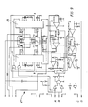
- FIG. 9 shows an exemplary embodiment of a frequency converter 27 with a counter AB, where the drive frequency is supplied to power drivers 28, which are arranged in push-pull, via inverters in conjunction with a gate by AND gates.
- a control pulse which is generated by the Hall sensor 26, is supplied via the input C, D and is further amplified via amplification elements and, after a query of the control frequency, is fed to control inputs of the output stages 28 in the manner of a control.
- the output stages 28 are supplied by a supply voltage (not shown in more detail) and control the motor at their outputs via power drivers T1, T2 or T3 and T4. Furthermore, switching elements for frequency compensation and for suppressing disturbances or start-up processes are provided. By increasing or decreasing the control frequency at the input of the frequency converter, the motor can be driven to any very high speed, with the Hall sensor 26 adjusting the desired speed by controlling the output stages 28.
Landscapes
- Engineering & Computer Science (AREA)
- Power Engineering (AREA)
- Motor Or Generator Cooling System (AREA)
- Control Of Motors That Do Not Use Commutators (AREA)
- Detergent Compositions (AREA)
- Electric Suction Cleaners (AREA)
- Electric Vacuum Cleaner (AREA)
- Structures Of Non-Positive Displacement Pumps (AREA)
- Brushless Motors (AREA)
- Organic Low-Molecular-Weight Compounds And Preparation Thereof (AREA)
- Lubricants (AREA)
- Dc Machiner (AREA)
- Motor Or Generator Frames (AREA)
- Control Of Ac Motors In General (AREA)
- Moving Of Heads (AREA)
Priority Applications (1)
| Application Number | Priority Date | Filing Date | Title |
|---|---|---|---|
| AT90112010T ATE100691T1 (de) | 1989-07-14 | 1990-06-25 | Elektronisch kommutierter motor fuer staubsauger und dergleichen. |
Applications Claiming Priority (2)
| Application Number | Priority Date | Filing Date | Title |
|---|---|---|---|
| DE3923267A DE3923267A1 (de) | 1989-07-14 | 1989-07-14 | Elektronisch kommutierter motor fuer staubsauger und dergleichen |
| DE3923267 | 1989-07-14 |
Publications (3)
| Publication Number | Publication Date |
|---|---|
| EP0413113A2 true EP0413113A2 (fr) | 1991-02-20 |
| EP0413113A3 EP0413113A3 (en) | 1991-05-22 |
| EP0413113B1 EP0413113B1 (fr) | 1994-01-26 |
Family
ID=6385005
Family Applications (1)
| Application Number | Title | Priority Date | Filing Date |
|---|---|---|---|
| EP90112010A Expired - Lifetime EP0413113B1 (fr) | 1989-07-14 | 1990-06-25 | Moteur commuté électroniquement pour aspirateur de poussière etc. |
Country Status (9)
| Country | Link |
|---|---|
| US (1) | US5394041A (fr) |
| EP (1) | EP0413113B1 (fr) |
| JP (1) | JP2630669B2 (fr) |
| KR (1) | KR0156243B1 (fr) |
| AT (1) | ATE100691T1 (fr) |
| BR (1) | BR9003362A (fr) |
| DE (2) | DE3923267A1 (fr) |
| DK (1) | DK0413113T3 (fr) |
| ES (1) | ES2050307T3 (fr) |
Cited By (5)
| Publication number | Priority date | Publication date | Assignee | Title |
|---|---|---|---|---|
| GB2286293A (en) * | 1993-12-23 | 1995-08-09 | London Innovation Limited | Adjustable stator: winding construction: cooling and commutator construction inan electric machine |
| EP0766366A1 (fr) * | 1995-09-29 | 1997-04-02 | BITRON S.p.A. | Direction assistée |
| EP0784369A1 (fr) | 1996-01-11 | 1997-07-16 | SA-Patent AG | Ventilateur à bypass entraîné par moteur électrique |
| EP1025792A3 (fr) * | 1999-02-08 | 2002-05-29 | AMETEK ITALIA S.r.l. | Unité d'aspiration actionnée par moteur électrique comprenant roue de refroidissement |
| CN1306896C (zh) * | 2004-10-27 | 2007-03-28 | 金骏达电机制造厂有限公司 | 用微电机驱动金属吸尘组件的构成方法和联结结构 |
Families Citing this family (23)
| Publication number | Priority date | Publication date | Assignee | Title |
|---|---|---|---|---|
| US5363867A (en) * | 1992-01-21 | 1994-11-15 | Shinko Electric Co., Ltd. | Article storage house in a clean room |
| US5691590A (en) * | 1992-10-23 | 1997-11-25 | Nippondenso Co., Ltd. | Alternator with magnetic noise reduction mechanism |
| US5708316A (en) * | 1992-10-23 | 1998-01-13 | Nippondenso Co., Ltd. | Altenator for a vehicle |
| US5574321A (en) * | 1994-05-04 | 1996-11-12 | Emerson Electric Co. | Integral refrigerator motor fan blades |
| DE4416299A1 (de) * | 1994-05-09 | 1995-11-16 | Abb Management Ag | Elektrische Maschine mit einem Axialventilator |
| RU2098908C1 (ru) * | 1995-03-07 | 1997-12-10 | Товарищество с ограниченной ответственностью "ПЭТРО-ФЭСТ" | Вентильный электродвигатель |
| US5751079A (en) * | 1996-10-17 | 1998-05-12 | Ford Motor Company | Alternator with internal and external fans |
| US6166462A (en) * | 1998-05-04 | 2000-12-26 | Ametek, Inc. | Bypass motor/fan assembly having separate working air passages |
| FR2778327B1 (fr) * | 1998-05-07 | 2000-06-30 | Seb Sa | Dispositif d'aspiration |
| US6439843B1 (en) | 2000-11-16 | 2002-08-27 | Ametek, Inc. | Motor/fan assembly having a radial diffuser bypass |
| JP4118548B2 (ja) * | 2001-11-06 | 2008-07-16 | 株式会社デンソー | 車両用交流発電機 |
| GB0202835D0 (en) * | 2002-02-07 | 2002-03-27 | Johnson Electric Sa | Blower motor |
| US7252482B2 (en) * | 2004-08-24 | 2007-08-07 | Beckett Corporation | Motor driven pump with improved motor cooling air flow |
| USD551167S1 (en) * | 2005-03-09 | 2007-09-18 | Matsushita Electric Industrial Co., Ltd. | Motor |
| GB0724837D0 (en) * | 2007-12-20 | 2008-01-30 | Edwards Ltd | vacuum pump |
| CN101592158A (zh) * | 2008-05-28 | 2009-12-02 | Gmj设计公司 | 改进的冷却气流电马达驱动泵 |
| US20110091330A1 (en) * | 2009-10-21 | 2011-04-21 | Deoliviera Marcelo | Condensate Removal Pump Controller Using Acoustic Liquid Level Sensor |
| CN102114483B (zh) * | 2009-12-31 | 2015-04-15 | 曾世雄 | 工业除尘装置 |
| CN102784994B (zh) * | 2012-05-24 | 2015-04-22 | 盐城市康杰机械制造有限公司 | 铝钎焊预热炉循环风机 |
| CN203384069U (zh) * | 2013-07-17 | 2014-01-08 | 中山大洋电机股份有限公司 | 一种引风机 |
| US9453427B2 (en) | 2013-10-30 | 2016-09-27 | General Electric Company | Systems and methods for purging an aft joint of a last stage wheel |
| KR102306127B1 (ko) | 2017-05-30 | 2021-09-29 | 엘지전자 주식회사 | 모터 |
| US20250098912A1 (en) * | 2023-09-26 | 2025-03-27 | GM Global Technology Operations LLC | Explosion-proof wet separator vacuum |
Family Cites Families (52)
| Publication number | Priority date | Publication date | Assignee | Title |
|---|---|---|---|---|
| GB309294A (en) * | 1928-03-29 | 1929-04-11 | Ml Magneto Syndicate Ltd | Improvements relating to dynamo electric machines |
| DE668436C (de) * | 1935-11-02 | 1938-12-03 | Siemens Schuckertwerke Akt Ges | Wicklungsloser Laeufer fuer elektrische Maschinen mit aus Dauermagnetstahl bestehenden prismenfoermigen Polstuecken trapezfoermigen Querschnitts |
| US2601517A (en) * | 1949-11-01 | 1952-06-24 | Dorothy C Hammes | Synchronous motor |
| US2726807A (en) * | 1950-09-28 | 1955-12-13 | Finnell System Inc | Vacuum apparatus for water and dirt removal |
| DE1139197B (de) * | 1954-04-08 | 1962-11-08 | Hermann Papst | Drehfeldmaschine mit hysteretischer Wirkung |
| US2822122A (en) * | 1955-05-06 | 1958-02-04 | American Machine & Metals | Vacuum cleaner motor and fan assembly |
| US2985779A (en) * | 1957-09-09 | 1961-05-23 | Gen Motors Corp | Permanent magnet rotor construction |
| BE571913A (fr) * | 1958-07-10 | |||
| DE1212625B (de) * | 1963-10-23 | 1966-03-17 | Licentia Gmbh | Halterung eines duennwandigen Dauermagnet-ringes aus Oxydwerkstoff im Laeufer eines Elektromotors |
| US3263908A (en) * | 1964-05-15 | 1966-08-02 | Nat Union Electric Corp | Cooling arrangement for a vacuum cleaner motor or the like |
| FR1440924A (fr) * | 1965-05-13 | 1966-06-03 | Nat Union Electric Corp | Dispositif de refroidissement pour moteur d'aspirateur de poussières et similaires |
| DE1628304A1 (de) * | 1967-04-14 | 1971-08-12 | Korrokunststoff Korrosionstech | Radialluefter |
| US3610975A (en) * | 1969-07-30 | 1971-10-05 | Westinghouse Electric Corp | Dynamoelectric machine with improved cooling means |
| DE1941418C3 (de) * | 1969-08-14 | 1978-01-05 | Hanning Elektro-Werke Robert Hanning, 4800 Bielefeld | Umwälzgebläse für Heissluftkammern |
| JPS5128322B1 (fr) * | 1970-11-14 | 1976-08-18 | ||
| DE2003905A1 (de) * | 1970-01-29 | 1971-08-05 | Siemens Elektrogeraete Gmbh | Staubsaugergeblaese mit eigenbelueftetem Antriebsmotor |
| CA977909A (en) * | 1972-08-18 | 1975-11-18 | Christopher R. Smallbone | Motor-fan device for vacuum cleaners |
| US3875436A (en) * | 1973-07-16 | 1975-04-01 | Scott & Fetzer Co | Double insulated vacuum cleaner motor housing |
| JPS5128610A (en) * | 1974-09-04 | 1976-03-11 | Hitachi Ltd | Museiryushimoota no sokudoseigyokairo |
| US4096419A (en) * | 1975-09-12 | 1978-06-20 | Plessey Handel Und Investments Ag. | Electric motors |
| US4120616A (en) * | 1975-10-06 | 1978-10-17 | Breuer Electric Manufacturing Company | Vacuum cleaner-blower assembly with sound absorbing arrangement |
| GB1565537A (en) * | 1975-10-23 | 1980-04-23 | Hitachi Ltd | Electric motor |
| USRE32027E (en) * | 1977-05-23 | 1985-11-12 | Ametek, Inc. | Wet pick-up vacuum unit motor bearing air seal |
| DE2945865A1 (de) * | 1979-11-14 | 1981-06-04 | Robert Bosch Gmbh, 7000 Stuttgart | Staubsaugergeblaese |
| DE3010435A1 (de) * | 1980-03-19 | 1981-09-24 | Papst-Motoren Kg, 7742 St Georgen | Kollektorloser gleichstrommotor |
| JPS576591A (en) * | 1980-06-11 | 1982-01-13 | Japan Servo Co Ltd | Direct current brushless motor and drive controller thereof |
| US4479078A (en) * | 1980-06-20 | 1984-10-23 | Kollmorgen Technologies Corporation | Brushless motor controller |
| DD157886A1 (de) * | 1981-04-03 | 1982-12-15 | Elektrogeraete Ingbuero Veb | Motorgeblaeseeinheit |
| DE3145232A1 (de) * | 1981-11-13 | 1983-06-01 | Quick-Rotan Elektromotoren GmbH, 6100 Darmstadt | Antrieb fuer arbeitsmaschinen, insbesondere industrienaehmaschinen |
| JPH0728553B2 (ja) * | 1982-03-31 | 1995-03-29 | 株式会社日立製作所 | モータの駆動回路 |
| US4528485A (en) * | 1982-04-13 | 1985-07-09 | General Electric Company | Electronically commutated motor, method of operating such, control circuit, laundry machine and drive therefor |
| DE3239665A1 (de) * | 1982-06-09 | 1983-12-15 | Ebm Elektrobau Mulfingen Gmbh & Co, 7119 Mulfingen | Kollektorloser gleichstrommotor |
| DE3229458A1 (de) * | 1982-08-06 | 1984-02-09 | Ryoji Nerima Tokyo Minegishi | Geblaese mit motor |
| JPS5959054A (ja) * | 1982-09-27 | 1984-04-04 | Fanuc Ltd | 永久磁石界磁回転子構造 |
| JPS6024182U (ja) * | 1983-07-22 | 1985-02-19 | 株式会社リコー | ホ−ルモ−タ |
| US4527960A (en) * | 1984-02-03 | 1985-07-09 | General Signal Corporation | Bearing air seal for vacuum cleaner motor |
| DE3427565C2 (de) * | 1984-07-26 | 1987-01-29 | Licentia Patent-Verwaltungs-Gmbh, 6000 Frankfurt | Durch einen Elektromotor angetriebenes Radialgebläse |
| US4621991A (en) * | 1985-02-22 | 1986-11-11 | Ametek, Inc. | Quiet by-pass vacuum motor |
| US4698534A (en) * | 1985-02-22 | 1987-10-06 | Ametek, Inc. | Quiet by-pass vacuum motor |
| JPS61199448A (ja) * | 1985-02-28 | 1986-09-03 | Fanuc Ltd | 永久磁石界磁回転子組立体 |
| US4669952A (en) * | 1985-05-17 | 1987-06-02 | Ametek, Inc. | Quiet by-pass vacuum motor |
| US4680515A (en) * | 1985-05-21 | 1987-07-14 | Crook James C | Digital speed control of motors |
| JPS61280752A (ja) * | 1985-06-05 | 1986-12-11 | Oopack Kk | 無刷子直流回転電機 |
| CH670017A5 (en) * | 1986-03-03 | 1989-04-28 | Papst Motoren Gmbh & Co Kg | Miniature permanent magnet electric motor - has narrow cylindrical air-gap and integral outer housing and stator of sintered metal |
| US4668898A (en) * | 1986-04-21 | 1987-05-26 | General Electric Company | Electronically commutated motor |
| US4642502A (en) * | 1986-04-24 | 1987-02-10 | General Motors Corporation | Dynamoelectric machine with permanent magnet and magnet mounting surface arrangement |
| US4801834A (en) * | 1986-04-30 | 1989-01-31 | General Electric Company | Rotor assembly |
| FR2603667B1 (fr) * | 1986-09-10 | 1990-09-28 | Etri Sa | Ventilateur centrifuge entraine par un moteur a courant continu et a commutation electronique |
| US4851017A (en) * | 1987-10-07 | 1989-07-25 | Rexair, Inc. | Radial cooling fan for vacuum cleaner motor |
| US4883982A (en) * | 1988-06-02 | 1989-11-28 | General Electric Company | Electronically commutated motor, blower integral therewith, and stationary and rotatable assemblies therefor |
| US4973872A (en) * | 1988-10-07 | 1990-11-27 | Emerson Electric Co. | Dynamoelectric machine rotor assembly with improved magnet retention stucture |
| SI8912097B (sl) * | 1989-10-30 | 1999-04-30 | Iskra-Elektromotorji, P.O., | Enofazni enosmerni motor brez krtačk z veliko hitrostjo in veliko močjo |
-
1989
- 1989-07-14 DE DE3923267A patent/DE3923267A1/de not_active Withdrawn
-
1990
- 1990-06-25 ES ES90112010T patent/ES2050307T3/es not_active Expired - Lifetime
- 1990-06-25 AT AT90112010T patent/ATE100691T1/de active
- 1990-06-25 DK DK90112010.5T patent/DK0413113T3/da active
- 1990-06-25 EP EP90112010A patent/EP0413113B1/fr not_active Expired - Lifetime
- 1990-06-25 DE DE90112010T patent/DE59004393D1/de not_active Expired - Fee Related
- 1990-07-11 KR KR1019900010438A patent/KR0156243B1/ko not_active Expired - Fee Related
- 1990-07-13 BR BR909003362A patent/BR9003362A/pt not_active IP Right Cessation
- 1990-07-16 JP JP2189255A patent/JP2630669B2/ja not_active Expired - Lifetime
-
1994
- 1994-04-04 US US08/222,504 patent/US5394041A/en not_active Expired - Lifetime
Cited By (7)
| Publication number | Priority date | Publication date | Assignee | Title |
|---|---|---|---|---|
| GB2286293A (en) * | 1993-12-23 | 1995-08-09 | London Innovation Limited | Adjustable stator: winding construction: cooling and commutator construction inan electric machine |
| US6040645A (en) * | 1993-12-23 | 2000-03-21 | London Innovation Ltd. | Electrical machines |
| US6459179B1 (en) | 1993-12-23 | 2002-10-01 | Cedric Lynch | Electrical machines |
| EP0766366A1 (fr) * | 1995-09-29 | 1997-04-02 | BITRON S.p.A. | Direction assistée |
| EP0784369A1 (fr) | 1996-01-11 | 1997-07-16 | SA-Patent AG | Ventilateur à bypass entraîné par moteur électrique |
| EP1025792A3 (fr) * | 1999-02-08 | 2002-05-29 | AMETEK ITALIA S.r.l. | Unité d'aspiration actionnée par moteur électrique comprenant roue de refroidissement |
| CN1306896C (zh) * | 2004-10-27 | 2007-03-28 | 金骏达电机制造厂有限公司 | 用微电机驱动金属吸尘组件的构成方法和联结结构 |
Also Published As
| Publication number | Publication date |
|---|---|
| BR9003362A (pt) | 1991-08-27 |
| KR0156243B1 (ko) | 1998-12-15 |
| ES2050307T3 (es) | 1994-05-16 |
| EP0413113A3 (en) | 1991-05-22 |
| DK0413113T3 (da) | 1994-05-24 |
| US5394041A (en) | 1995-02-28 |
| DE59004393D1 (de) | 1994-03-10 |
| ATE100691T1 (de) | 1994-02-15 |
| KR910003895A (ko) | 1991-02-28 |
| JP2630669B2 (ja) | 1997-07-16 |
| EP0413113B1 (fr) | 1994-01-26 |
| DE3923267A1 (de) | 1991-01-24 |
| JPH0390119A (ja) | 1991-04-16 |
Similar Documents
| Publication | Publication Date | Title |
|---|---|---|
| EP0413113B1 (fr) | Moteur commuté électroniquement pour aspirateur de poussière etc. | |
| DE3740725C2 (fr) | ||
| EP1051797B1 (fr) | Machine electrique | |
| DE2433087C2 (de) | Einbaulüfter zur Belüftung der Vorderseite einer flachen Einbauwand | |
| DE69812346T2 (de) | Motor | |
| EP1362404B1 (fr) | Machine electrique | |
| DE3932802A1 (de) | Staubsaugermotor | |
| DE19643362C2 (de) | Windgenerator | |
| DE3122655A1 (de) | "istwertgeber-vorrichtung" | |
| EP1389824A1 (fr) | Systeme de machine electrique | |
| DE29700643U1 (de) | Entwärmungskonzept für ein elektrisches Antriebssystem | |
| DE102019218437A1 (de) | Rotor für eine Elektromaschine und Verfahren zur Herstellung eines Rotors | |
| EP0345796A2 (fr) | Ventilateur entraîné par un moteur électrique | |
| WO2008080575A1 (fr) | Machine synchrone à aimants permanents | |
| DE102015011959A1 (de) | Starter-Anordnung | |
| EP2429065B1 (fr) | Machine électrique à excitation par aimants permanents | |
| EP0454664B1 (fr) | Machine electrique a arbre vertical | |
| DE2245009B2 (de) | Spaltrohrmotor für ein Pumpenaggregat mit Kunststoffgehäuse und mit Pumpenrad vereinigtem Rotor | |
| EP1081386A2 (fr) | Moteur électrique a flux axial | |
| DE3232914C1 (de) | Laeufer fuer einen Hysteresemotor | |
| DE4222131C2 (de) | Belüftungseinrichtung für die Druckbelüftung von oberflächenbelüfteten elektrischen Maschinen | |
| EP1516109B1 (fr) | Dispositif de refroidissement d'unite generatrice de courant | |
| EP3577745B1 (fr) | Refroidissement d'une machine électrique | |
| DE3925471A1 (de) | Vorrichtung zum umwandeln von luftdruck in elektrische energie | |
| DE9314984U1 (de) | Läufer für elektrische Maschinen mit Lüfter |
Legal Events
| Date | Code | Title | Description |
|---|---|---|---|
| PUAI | Public reference made under article 153(3) epc to a published international application that has entered the european phase |
Free format text: ORIGINAL CODE: 0009012 |
|
| AK | Designated contracting states |
Kind code of ref document: A2 Designated state(s): AT BE CH DE DK ES FR GB GR IT LI LU NL SE |
|
| PUAL | Search report despatched |
Free format text: ORIGINAL CODE: 0009013 |
|
| 17P | Request for examination filed |
Effective date: 19910312 |
|
| AK | Designated contracting states |
Kind code of ref document: A3 Designated state(s): AT BE CH DE DK ES FR GB GR IT LI LU NL SE |
|
| 17Q | First examination report despatched |
Effective date: 19921007 |
|
| GRAA | (expected) grant |
Free format text: ORIGINAL CODE: 0009210 |
|
| AK | Designated contracting states |
Kind code of ref document: B1 Designated state(s): AT BE CH DE DK ES FR GB GR IT LI LU NL SE |
|
| PG25 | Lapsed in a contracting state [announced via postgrant information from national office to epo] |
Ref country code: GR Free format text: LAPSE BECAUSE OF FAILURE TO SUBMIT A TRANSLATION OF THE DESCRIPTION OR TO PAY THE FEE WITHIN THE PRESCRIBED TIME-LIMIT Effective date: 19940126 |
|
| REF | Corresponds to: |
Ref document number: 100691 Country of ref document: AT Date of ref document: 19940215 Kind code of ref document: T |
|
| REF | Corresponds to: |
Ref document number: 59004393 Country of ref document: DE Date of ref document: 19940310 |
|
| ITF | It: translation for a ep patent filed | ||
| REG | Reference to a national code |
Ref country code: ES Ref legal event code: FG2A Ref document number: 2050307 Country of ref document: ES Kind code of ref document: T3 |
|
| REG | Reference to a national code |
Ref country code: DK Ref legal event code: T3 |
|
| GBT | Gb: translation of ep patent filed (gb section 77(6)(a)/1977) |
Effective date: 19940422 |
|
| ET | Fr: translation filed | ||
| EPTA | Lu: last paid annual fee | ||
| PLBE | No opposition filed within time limit |
Free format text: ORIGINAL CODE: 0009261 |
|
| 26N | No opposition filed | ||
| EAL | Se: european patent in force in sweden |
Ref document number: 90112010.5 |
|
| PGFP | Annual fee paid to national office [announced via postgrant information from national office to epo] |
Ref country code: BE Payment date: 20000405 Year of fee payment: 11 |
|
| PGFP | Annual fee paid to national office [announced via postgrant information from national office to epo] |
Ref country code: LU Payment date: 20000530 Year of fee payment: 11 |
|
| PGFP | Annual fee paid to national office [announced via postgrant information from national office to epo] |
Ref country code: ES Payment date: 20000615 Year of fee payment: 11 |
|
| PGFP | Annual fee paid to national office [announced via postgrant information from national office to epo] |
Ref country code: FR Payment date: 20000628 Year of fee payment: 11 Ref country code: SE Payment date: 20000628 Year of fee payment: 11 |
|
| PGFP | Annual fee paid to national office [announced via postgrant information from national office to epo] |
Ref country code: NL Payment date: 20000629 Year of fee payment: 11 |
|
| PGFP | Annual fee paid to national office [announced via postgrant information from national office to epo] |
Ref country code: AT Payment date: 20000630 Year of fee payment: 11 |
|
| PG25 | Lapsed in a contracting state [announced via postgrant information from national office to epo] |
Ref country code: AT Free format text: LAPSE BECAUSE OF NON-PAYMENT OF DUE FEES Effective date: 20010625 Ref country code: LU Free format text: LAPSE BECAUSE OF NON-PAYMENT OF DUE FEES Effective date: 20010625 |
|
| PG25 | Lapsed in a contracting state [announced via postgrant information from national office to epo] |
Ref country code: ES Free format text: LAPSE BECAUSE OF NON-PAYMENT OF DUE FEES Effective date: 20010626 Ref country code: SE Free format text: LAPSE BECAUSE OF NON-PAYMENT OF DUE FEES Effective date: 20010626 |
|
| PG25 | Lapsed in a contracting state [announced via postgrant information from national office to epo] |
Ref country code: BE Free format text: LAPSE BECAUSE OF NON-PAYMENT OF DUE FEES Effective date: 20010630 |
|
| BERE | Be: lapsed |
Owner name: WAP REINIGUNGSSYSTEME G.M.B.H. & CO. Effective date: 20010630 |
|
| PG25 | Lapsed in a contracting state [announced via postgrant information from national office to epo] |
Ref country code: NL Free format text: LAPSE BECAUSE OF NON-PAYMENT OF DUE FEES Effective date: 20020101 |
|
| REG | Reference to a national code |
Ref country code: GB Ref legal event code: IF02 |
|
| EUG | Se: european patent has lapsed |
Ref document number: 90112010.5 |
|
| PG25 | Lapsed in a contracting state [announced via postgrant information from national office to epo] |
Ref country code: FR Free format text: LAPSE BECAUSE OF NON-PAYMENT OF DUE FEES Effective date: 20020228 |
|
| NLV4 | Nl: lapsed or anulled due to non-payment of the annual fee |
Effective date: 20020101 |
|
| PGFP | Annual fee paid to national office [announced via postgrant information from national office to epo] |
Ref country code: CH Payment date: 20020625 Year of fee payment: 13 |
|
| REG | Reference to a national code |
Ref country code: ES Ref legal event code: FD2A Effective date: 20030203 |
|
| PGFP | Annual fee paid to national office [announced via postgrant information from national office to epo] |
Ref country code: DE Payment date: 20030514 Year of fee payment: 14 |
|
| PGFP | Annual fee paid to national office [announced via postgrant information from national office to epo] |
Ref country code: DK Payment date: 20030616 Year of fee payment: 14 |
|
| PG25 | Lapsed in a contracting state [announced via postgrant information from national office to epo] |
Ref country code: LI Free format text: LAPSE BECAUSE OF NON-PAYMENT OF DUE FEES Effective date: 20030630 Ref country code: CH Free format text: LAPSE BECAUSE OF NON-PAYMENT OF DUE FEES Effective date: 20030630 |
|
| REG | Reference to a national code |
Ref country code: CH Ref legal event code: PL |
|
| PG25 | Lapsed in a contracting state [announced via postgrant information from national office to epo] |
Ref country code: DK Free format text: LAPSE BECAUSE OF NON-PAYMENT OF DUE FEES Effective date: 20040630 |
|
| PG25 | Lapsed in a contracting state [announced via postgrant information from national office to epo] |
Ref country code: DE Free format text: LAPSE BECAUSE OF NON-PAYMENT OF DUE FEES Effective date: 20050101 |
|
| REG | Reference to a national code |
Ref country code: DK Ref legal event code: EBP |
|
| PG25 | Lapsed in a contracting state [announced via postgrant information from national office to epo] |
Ref country code: IT Free format text: LAPSE BECAUSE OF NON-PAYMENT OF DUE FEES;WARNING: LAPSES OF ITALIAN PATENTS WITH EFFECTIVE DATE BEFORE 2007 MAY HAVE OCCURRED AT ANY TIME BEFORE 2007. THE CORRECT EFFECTIVE DATE MAY BE DIFFERENT FROM THE ONE RECORDED. Effective date: 20050625 |
|
| PGFP | Annual fee paid to national office [announced via postgrant information from national office to epo] |
Ref country code: GB Payment date: 20080609 Year of fee payment: 19 |
|
| GBPC | Gb: european patent ceased through non-payment of renewal fee |
Effective date: 20090625 |
|
| PG25 | Lapsed in a contracting state [announced via postgrant information from national office to epo] |
Ref country code: GB Free format text: LAPSE BECAUSE OF NON-PAYMENT OF DUE FEES Effective date: 20090625 |