EP0413371A2 - Automatische Vorrichtung zum Falzen von Bögen - Google Patents
Automatische Vorrichtung zum Falzen von Bögen Download PDFInfo
- Publication number
- EP0413371A2 EP0413371A2 EP90201523A EP90201523A EP0413371A2 EP 0413371 A2 EP0413371 A2 EP 0413371A2 EP 90201523 A EP90201523 A EP 90201523A EP 90201523 A EP90201523 A EP 90201523A EP 0413371 A2 EP0413371 A2 EP 0413371A2
- Authority
- EP
- European Patent Office
- Prior art keywords
- elements
- accompanying
- sheet elements
- unit
- belts
- Prior art date
- Legal status (The legal status is an assumption and is not a legal conclusion. Google has not performed a legal analysis and makes no representation as to the accuracy of the status listed.)
- Granted
Links
Images


Classifications
-
- B—PERFORMING OPERATIONS; TRANSPORTING
- B65—CONVEYING; PACKING; STORING; HANDLING THIN OR FILAMENTARY MATERIAL
- B65H—HANDLING THIN OR FILAMENTARY MATERIAL, e.g. SHEETS, WEBS, CABLES
- B65H45/00—Folding thin material
- B65H45/12—Folding articles or webs with application of pressure to define or form crease lines
- B65H45/22—Longitudinal folders, i.e. for folding moving sheet material parallel to the direction of movement
Definitions
- This invention relates to an automatic apparatus for folding sheet elements.
- sheet elements is intended to mean either a single paper sheet or an editorial graphic product.
- An editorial product in this context means a newspaper, a magazine, or a signature etc.
- the product can be either a single product or a folded product or a number of superposed single or folded products.
- such sheets after leaving the conventional printing and folding machines may have to be fed in a specially folded manner and/or arranged with a determined specific positioning rehired for their subsequent wrapping.
- An object of the present invention is to provide an apparatus able to automatically fold said sheet elements in accordance with the specific requirement and which if required can be arranged directly aligned with the inlet of a product wrapping machine, such as that initially referred to, or be manually or automatically connected downstream of the production process for said sheet elements.
- a further object is to provide an apparatus able to fold said sheet elements irrespective of their thickness or the multiple state of their composition.
- an automatic apparatus for folding sheet elements fed one after the other in succession along their direction of advancement characterised by comprising a frame supporting a first shaping unit which forms said sheet elements into U-shape to define two vertical side portions and a longitudinal central region within said sheet elements, said first shaping unit consisting of means for gripping and accompanying said central region, and associated with lateral support and accompanying elements for rotating said two side portions of said sheet elements from a first position in the feed plane to a second position in which they are parallel, separated and side by side, a pusher element for V-shaping said central region, and a second unit for the final compaction of said V-shaped sheet elements and consisting of lateral walls for compressing said central region and retaining elements for accompanying said thus folded sheet elements towards a subsequent station.
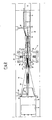
- an automatic apparatus for folding sheet elements 11 which arrive for example from a printing machine, not shown and are fed one after the other in succession either in register or not, for example by a push-type conveyor indicated schematically at 12, comprises assentially a frame 13 for supporting a first shaping unit, indicated overall by 14, and a second unit, indicated overall by 15, for the final compaction of the sheet elements.
- a pusher element indicated overall by 16 for V-shaping a flat central region 17 of the sheet elements 11.
- a third unit, indicated overall by 18, can also be provided for the 90° rotation of the thus folded sheet elements 11 emerging from the second unit 15.
- the first shaping unit 14 shapes the sheet elements 11 into a U with sharp edges ( Figure 4) to define two vertical lateral portions 19 and the longitudinal flat central region 17.
- Said first shaping unit 14 consists of means for gripping and accompanying the flat central region 17, these means being associated with lateral support and accompanying elements for rotating the two side portions 19 of the sheet elements 11 from a first position in the feed plane of the conveyor 12 to a second position in which they are parallel, separated and side by side ( Figure 4).
- Said means for gripping and accompanying the first shaping unit 14 consist of a pair of conveyors in the form of endless flat guide belts 20 and 21 extending between end pulleys 22, 22′.
- Said guide belts which are vertical and mutually facing one above the other, comprise a first lower belt 20 on which the flat central region 17 of the sl,eet elements 11 rests, and a second upper belt 21 of small transverse dimensions, to be inserted between the two vertical side portions 19 of the sheet elements 11.
- the second upper belt 21 can be of essentially toroidal form to generate a central portion 17 in the U-shaped sheet elements which does not have sharp edges but which instead smoothly blends into the two vertical side portions 19.
- the first lower belt 20 is motorized, for example by a first transmission 23, which rotates the pulley 22′ and extends from the output side of a reduction gear 24.
- the reduction gear 24 is driven by a further transmission 25 from a rigid drive shaft 26 extending longitudinally to the apparatus of the invention and driven by the main motor 27.
- the second upper belt 21 is for example motorized by a transmission shaft 28 which drives the drive pulley 22′ and is itself driven by the drive for the first lower belt 20 via a gearwheel coupling (not shown) which provides the same speed of advancement to the belts.
- the second upper belt 21 is arranged on a frame 29 upperly comprising a pair of guide rods 30, which are centrally arranged on it and on which there slides a cross-member 31 adjustable in height by a manually operable adjustment device 32, for example of screw type. Between the cross-member 31 and the top of the frame 29 there are provided, coaxially to the guide rods 30, elastic elements 33 which allow the frame 29 to undergo slight vertical movement so as to adapt the position of the second upper belt 21 to the inserted sheet elements on the first lower belt 20.
- the adjustment device 32 is rigid with a structure 34 arranged to the side of the first shaping unit 14 and enabling the entire second upper belt 21 to be raised and lowered by vertical actuator cylinders 35.
- guide rollers 36 On the frame 29 in a position corresponding with the lower part of the second upper belt 21 which faces said first lower belt 20 there are provided guide rollers 36, which are supported on the frame 29 via elastic elements 37.
- the provision of these latter guide rollers 36 allows the lower portion of the belt 21 to be adapted to the individual sheet elements 11 fed one after the other and contained within it.
- the lateral support and accompanying elements for the rotation of the two side portions 19 of the sheet elements 11 shown in Figures 1 and 2 are fixed guides 38 which face each other and are positioned on opposite sides of said gripping and accompanying means or rather of said second upper belt 21, and in addition are mutually specular and are of helix shape to rotate the two side portions 19 of the sheet elements 11 through 90°.
- said fixed guides 38 can be supported on the ends of the rods of cylinders 10 which enable the guides to be raised to if necessary allow the passage of extended open sheet elements between the belts 20 and 21.
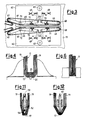
- FIG. 5 shows an embodiment of the pusher element 16 for V-shaping the sheet element, and consisting of a guide rod 46 pivoted at one end, at 47, to the support frame 29 for the second upper belt 21 and forming part of the gripping and accompanying means of the first shaping unit 14.
- the guide rod 46 is kept essentially horizontal by an elastic downwardly-urging element 48 coaxially arranged on a pivot 49 and reacting against an appendix 50jutting from the frame 29.
- the entire pusher element 16 can be moved vertically relative to the frame 29 by elements for its vertical position adjustment, for example by an adjustment screw shown schematically at 51.
- the vertical height adjustment of the pusher element 16 could be accomplished automatically by a suitable actuator means (not shown).
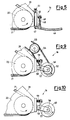
- the second unit for the final compacting of the sheet elements 11, indicated by 15, is arranged at the exit of the first shaping unit 14 and receives the sheet elements already V-shaped (as shown for example in Figures 11 and 12).
- the second unit 15 consists essentially of lateral elements for compressing said already V-shaped central region 17, and retaining and accompanying elements for said thus folded sheet elements which act on the vertical side portions 19 of the sheet elements 11.
- the lateral retaining and accompanying elements consist of a pair of belts 61 which face each other horizontally at the sides of the two vertical side portions 19 of the sheet elements 11, and are disposed on two support plates 62 which are rigid with the apparatus framework 13 but are adjustable in height by a screw with a handwheel indicated schematically by 63.
- a pair of essentially L-shaped front levers 65 and rear levers 66 are pivoted at 64, on a vertical axis, on each of said support plates 62 approximately in proximity to the edge facing the other plate and centrally thereto, so that the two minor sides of the L are side by side.
- Each of said front and rear levers 65 and 66 rotatably carries a deviation pulley 67 and 68 respectively, at that free end distant from the major side of the L.
- the other end of said L-shaped levers 65 and 66 is connected to elastic elements 69 which urge the two side-by-side minor sides of the levers apart, to consequently cause the deviation pulleys 67 and 68 and the belts 61 to approach the centre of the second unit 15 in a direction transverse to the apparatus, ie to approach the folded sheet elements contained in this latter unit.
- An end region of the front levers 65 is V-shaped and open towards the first shaping unit 14 to at least partly embrace it laterally.
- This open-V end region is defined by at least one further idle guide roller 72 for the belts 61.
- the belts 61 In positions corresponding with the major sides of the front and rear levers 65 and 66 there are provided for the belts 61 further mutually facing idle guide rollers 70 carrying associated elastic elements 71 which make them yieldably supported on the levers 65 and 66.
- the lateral compressing elements of the second unit 15 consist of a further pair of belts 73 which essentially face each other horizontally but diverge in V form towards the pusher element 16.
- the belts 73 extend endlessly about an idle end pulley 74 and a motorized end pulley 75 respectively. Further intermediate idle pulleys 74 are provided acting on the facing portions of the belts 73. All the pulleys 74 and 75 are pivoted vertically on a pair of slides 76 which are maintained in their correct adjacent position by elastic elements 77 coaxially pitted on a column 78.
- the slides 76 can move horizontally along guide shafts 79 and vertically along guide columns 80, there being provided for example an actuator means such as a piston 81 for the vertical movement.
- the motorized pulleys 75 are driven via a splined shaft coupling 82 rotated by a transmission 83, this latter being driven by the said drive shaft 26.
- One end of said final pair of belts 84 is aligned with the exit of the first retaining and accompanying elements represented by the belts 61, the other end being rotated helically through 90° so that the sheet elements 11 are also rotated through 90° during their conveying from one end to the other, this rotation being possible in one direction or the other as required.
- the belts 84 pass at one end about pulleys 85 axially aligned with the pulleys 68, whereas at their other end they pass about motorized pulleys 86 driven by shafts 87 rotated by a transmission 88, which is also driven by the drive shaft 26.
- the upper pulley 86 rotating about a horizontal axis, can be moved vertically against yieldable elastic elements 89. Coupling the pulleys 68 and 85 on the same shaft means that the transmission 88 drives not only the belts 84 of the third unit 18 but also the preeceding belts 61 of the second unit 15.
- Elements 90 for separating the adjacent upper parallel end edges of the two side portions 19 of the sheet elements 11 are associated with both said first and said second longitudinal lateral retaining and dispatchying elements 61 and 84.
- Said separator elements 90 are for example in the form of a narrow continuous plate extending vertically along the second unit 15, then twisted as a parallel helix axially interposed between the belts 84 of the third unit 18 and then extending horizontally along the further travel of the sheet elements 11, to keep their side portions 19 permanently separated.
- a conveyor element 91 Associated with the first lower belt 20 and extending from it along both the second unit 15 and the third unit 18 there is a conveyor element 91, also consisting for example of a pair of endless belts passing at one end about pulleys coaxial to the pulley 22 and motorized at their other end by end pulleys 92.
- This motorization is provided by a transmission 93, which can be in partial relationship with the transmission 88 and also derives from the drive shaft 26.
- a second conveyor 94 of pusher type, is provided between said two belts 91 to expel the correctly folded sheet elements 11 leaving the third unit 18 and possibly comprising side portions 19 kept separated by the separator elements 90.
- Figures 7 and 8 show a second alternative embodiment of the lateral support and accompanying elements of the first shaping unit 14.
- the lateral elements consist of endless conveyor belts 39 also facing each other specularly on opposite sides of the gripping and accompanying means and arranged to form a portion of a helix. It is interesting to note that the speed of said conveyor belts must exceed that of the gripping and accompanying means represented by the upper and lower belts 21 and 20, because these latter undergo a linear movement whereas the former travel through a greater distance likeable to a diagonal.
- a further embodiment can be provided by way of example in which the conveyor belts 39 comprise a plurality of holes 40 in their surface and are slidable, along their facing specular portion, on box elements 41 operationally connectable to a pump for creating vacuum and schematically indicated by 42.
- these box elements also comprise a plurality of holes (not shown) by which, in combination with the plurality of holes 40 provided in the conveyor belts, they retain the side portions 19 of the sheet elements 11, especially when these sheet elements are light and consist for example of a single sheet.
- Motorization of the conveyor belts 39 in both these latter embodiments can be advantageously obtained by shafts 43 emerging from an end pulley 44 and connected for example to the drive of the second upper belt 21 by way of a suitable speed reduction or variation gear indicated schematically by 45.
- Figures 9 and 11 show a second embodiment of the pusher element 16 in which this latter consists of a wheel 52 comprising a central groove 53 in which a belt 54 is inserted to rotate it by means of a motorized transmission indicated overall by 55 and partly shown.
- the wheel 52 is pivoted at 56 on one end of a support bar 57, which is pivoted at 58 to the frame 29.
- the support bar 57 is of right angled shape and is urged at its other end downwards and away from said frame 29 by an elastic element 59. In this manner (Figure 11), the wheel 52 is kept in contact with the central region 17 of the sheet elements 11 to form it into V-shape.
- Figures 10 and 12 show a third embodiment of the pusher element, which is identical to that just described with the exception that in this case the roller 60 is idle.
- Figure 12 shows how again in this case the idle roller 60 interferes with the central region 17 to form it into V-shape.
- the vertical height adjustment device for the pusher element 16 has been omitted for simplicity, but it could be provided.
- the operation of an automatic apparatus for folding sheet elements according to the present invention is as follows.
- An individual sheet element 11 enters the first shaping unit 14 between the upper band 21 and lower band 20 at the drive pulleys 22′ and is retained and dragged along by these.
- the side portions 19 slide guidedly on the fixed guides 38 or belts 39, and because of the particular shape of these latter are displaced from their first horizontal feed position, to a second vertical position shown in Figure 4.
- the elastic elements 33 and yieldable idle rollers 36 enable the upper belt 21 to move vertically to adapt to the thickness of the advancing sheet element 11.
- the U-folded sheet element 11 or rather its central region 17 comes into contact with the pusher element 16 which V-shapes it as shown in Figure 11 or 12.
- the side portions 19 of the sheet element 11 are retained and accompanied by the belts 61 of the second apparatus unit 15.
- the central region 17 is fed within the bands 73 forming part of the lateral compression elements until it finally emerges compressed as shown in Figure 6 at the motorized end pulleys 75.
- the sheet element 11 is then accompanied by the belts 61 to the third unit which, arranged to correspond with the middle of the side portions 19 of the sheet element 11, grips it and conveys it, to rotate it through 90° by the time it reaches the exit of said third unit.
- the sheet element 11, now folded as required, then leaves the third unit to lie on the outlet conveyor element 91, to be expelled by the second pusher conveyor 94.
- the upper separator element 90 enables the upper edges of the side portions 19 of said sheet element to be kept separated for the possible insertion of additional sheets.
- An apparatus according to the present invention allows completely automatic folding of any sheet element, a perfect shaping of the fold irrespective of the thickness of the sheet element concerned and, by possible rotation, the emergence of the folded sheet in any predetermined required arrangement.
- sheet elements can pass through the entire apparatus in the same arrangement as that in which they are fed, without undergoing any folding.
- the sheet elements travel securely between them without any deterioration on slippage, deterioration being particularly important in the case of printed or particularly delicate sheet elements and slippage being important in the case of superposed or composite sheet elements.
Landscapes
- Folding Of Thin Sheet-Like Materials, Special Discharging Devices, And Others (AREA)
- Selective Calling Equipment (AREA)
- Details Of Television Systems (AREA)
- Packaging Of Special Articles (AREA)
- Shaping Of Tube Ends By Bending Or Straightening (AREA)
Priority Applications (1)
| Application Number | Priority Date | Filing Date | Title |
|---|---|---|---|
| AT9090201523T ATE105264T1 (de) | 1989-06-19 | 1990-06-13 | Automatische vorrichtung zum falzen von boegen. |
Applications Claiming Priority (2)
| Application Number | Priority Date | Filing Date | Title |
|---|---|---|---|
| IT2091489 | 1989-06-19 | ||
| IT8920914A IT1230871B (it) | 1989-06-19 | 1989-06-19 | Apparecchiatura automatica per la piegatura di elementi a foglio. |
Publications (3)
| Publication Number | Publication Date |
|---|---|
| EP0413371A2 true EP0413371A2 (de) | 1991-02-20 |
| EP0413371A3 EP0413371A3 (en) | 1991-06-12 |
| EP0413371B1 EP0413371B1 (de) | 1994-05-04 |
Family
ID=11174007
Family Applications (1)
| Application Number | Title | Priority Date | Filing Date |
|---|---|---|---|
| EP90201523A Expired - Lifetime EP0413371B1 (de) | 1989-06-19 | 1990-06-13 | Automatische Vorrichtung zum Falzen von Bögen |
Country Status (10)
| Country | Link |
|---|---|
| US (1) | US5090672A (de) |
| EP (1) | EP0413371B1 (de) |
| JP (1) | JP2786523B2 (de) |
| AT (1) | ATE105264T1 (de) |
| CA (1) | CA2018798C (de) |
| DE (1) | DE69008643T2 (de) |
| DK (1) | DK0413371T3 (de) |
| ES (1) | ES2052159T3 (de) |
| FI (1) | FI100236B (de) |
| IT (1) | IT1230871B (de) |
Cited By (3)
| Publication number | Priority date | Publication date | Assignee | Title |
|---|---|---|---|---|
| EP0922662A1 (de) * | 1997-12-04 | 1999-06-16 | Grapha-Holding Ag | Anordnung zum Verarbeiten der Papierbahn einer Rollendruckmaschine |
| EP1108672A3 (de) * | 1999-12-15 | 2004-03-24 | Heidelberger Druckmaschinen Aktiengesellschaft | Verfahren und Vorrichtung zum linearen Falzen |
| EP2281766A1 (de) * | 2009-08-03 | 2011-02-09 | Ferag AG | Vorrichtung und Verfahren zum Falzen eines Papiererzeugnisses |
Families Citing this family (22)
| Publication number | Priority date | Publication date | Assignee | Title |
|---|---|---|---|---|
| US6164438A (en) * | 1996-08-21 | 2000-12-26 | Vermehren; H. Richard | Adjustable control roller apparatus and method |
| JP2986102B1 (ja) | 1999-01-29 | 1999-12-06 | 中日本ジューキ株式会社 | シ―ト状体の折重ね装置 |
| JP2986101B1 (ja) | 1999-01-29 | 1999-12-06 | 中日本ジューキ株式会社 | シ―ト状体の折重ね装置 |
| US6935997B2 (en) * | 2000-09-14 | 2005-08-30 | Rutgers, The State University Of New Jersey | Patterning technology for folded sheet structures |
| US6565501B1 (en) | 2000-11-01 | 2003-05-20 | The Procter & Gamble Company | Method and apparatus for folding a web |
| JP4224303B2 (ja) | 2001-05-22 | 2009-02-12 | ユニ・チャーム株式会社 | 陰唇間パッド及びその包装体 |
| ATE454872T1 (de) | 2001-05-22 | 2010-01-15 | Uni Charm Corp | Interlabial-polster |
| ES2321914T3 (es) | 2001-05-22 | 2009-06-15 | Uni-Charm Corporation | Almohadilla interlabial. |
| CN1231196C (zh) | 2001-05-22 | 2005-12-14 | 尤妮佳股份有限公司 | 阴唇间吸湿垫及其包装体 |
| WO2002094153A1 (en) | 2001-05-22 | 2002-11-28 | Uni-Charm Corporation | Interlabial pad |
| CN1682674A (zh) | 2001-05-22 | 2005-10-19 | 尤妮佳股份有限公司 | 包装体 |
| WO2002094147A1 (en) | 2001-05-22 | 2002-11-28 | Uni-Charm Corporation | Interlabial pad |
| JP4566522B2 (ja) | 2002-08-30 | 2010-10-20 | ユニ・チャーム株式会社 | 吸収体の製造装置 |
| JP4217640B2 (ja) * | 2004-02-27 | 2009-02-04 | キヤノン株式会社 | シート束背面折り部平坦処理装置、シート束処理装置及び画像形成装置 |
| DE102004023318B4 (de) * | 2004-05-07 | 2008-04-17 | Man Roland Druckmaschinen Ag | Falzeinrichtung für Druckmaschinen oder Falzapparate |
| US8409066B2 (en) * | 2006-07-31 | 2013-04-02 | Kimberly-Clark Worldwide, Inc. | Method and apparatus for folding a web |
| US7686288B2 (en) * | 2007-01-18 | 2010-03-30 | Maschinenbau Oppenweiler Binder Gmbh & Co. Kg | Method and device for further processing of sheets to produce multi-page printed products |
| IT1396784B1 (it) * | 2009-11-25 | 2012-12-14 | Gingardi | Apparecchiatura per la finitura dei prodotti uscenti da una macchina per la piegatura ed incollatura di prodotti in cartone o cartoncino con dorso. |
| IT1398421B1 (it) * | 2010-02-26 | 2013-02-22 | Fameccanica Data Spa | Dispositivo e procedimento per piegare materiali in nastro |
| US8777825B1 (en) | 2010-10-12 | 2014-07-15 | Daniel Kling | Methods for designing boxes and other types of containers |
| IT201800005103A1 (it) * | 2018-05-07 | 2019-11-07 | Apparato piegatore di un nastro continuo | |
| IT201900019706A1 (it) * | 2019-10-24 | 2021-04-24 | Gdm Spa | Apparato piegatore di un nastro continuo |
Family Cites Families (8)
| Publication number | Priority date | Publication date | Assignee | Title |
|---|---|---|---|---|
| DE57590C (de) * | St. SKUCEK in Lieben bei Prag und F. JELEN in Prag, Hybernergasse 7 | Lederfärbmaschine | ||
| CH410997A (de) * | 1964-02-20 | 1966-04-15 | Tages Anzeiger Fuer Stadt Und | Falzmaschine |
| US3361425A (en) * | 1965-10-14 | 1968-01-02 | Benitez Ramon | Longitudinal folder for making paper napkins and the like articles from web material |
| US4046366A (en) * | 1976-06-09 | 1977-09-06 | Mccain Manufacturing Corporation | Method for producing books |
| DE3429172C2 (de) * | 1984-08-08 | 1986-10-30 | M.A.N.- Roland Druckmaschinen AG, 6050 Offenbach | Vorrichtung zum Längsfalzen übereinanderliegender Druckträgerbahnen |
| US4747817A (en) * | 1986-07-03 | 1988-05-31 | Newsome John R | High speed signature manipulating apparatus |
| US4784379A (en) * | 1987-03-24 | 1988-11-15 | Bell & Howell Company | Apparatus and method for automated mail |
| US4875668A (en) * | 1988-04-28 | 1989-10-24 | Computer Output Processors And Engineering, Inc. | High speed sheet folder and presser for automated mailing systems |
-
1989
- 1989-06-19 IT IT8920914A patent/IT1230871B/it active
-
1990
- 1990-06-12 CA CA002018798A patent/CA2018798C/en not_active Expired - Fee Related
- 1990-06-12 US US07/537,084 patent/US5090672A/en not_active Expired - Lifetime
- 1990-06-13 DK DK90201523.9T patent/DK0413371T3/da active
- 1990-06-13 AT AT9090201523T patent/ATE105264T1/de not_active IP Right Cessation
- 1990-06-13 EP EP90201523A patent/EP0413371B1/de not_active Expired - Lifetime
- 1990-06-13 ES ES90201523T patent/ES2052159T3/es not_active Expired - Lifetime
- 1990-06-13 DE DE69008643T patent/DE69008643T2/de not_active Expired - Fee Related
- 1990-06-18 FI FI903054A patent/FI100236B/fi active IP Right Grant
- 1990-06-19 JP JP2161191A patent/JP2786523B2/ja not_active Expired - Lifetime
Cited By (4)
| Publication number | Priority date | Publication date | Assignee | Title |
|---|---|---|---|---|
| EP0922662A1 (de) * | 1997-12-04 | 1999-06-16 | Grapha-Holding Ag | Anordnung zum Verarbeiten der Papierbahn einer Rollendruckmaschine |
| EP1108672A3 (de) * | 1999-12-15 | 2004-03-24 | Heidelberger Druckmaschinen Aktiengesellschaft | Verfahren und Vorrichtung zum linearen Falzen |
| EP2281766A1 (de) * | 2009-08-03 | 2011-02-09 | Ferag AG | Vorrichtung und Verfahren zum Falzen eines Papiererzeugnisses |
| CH701620A1 (de) * | 2009-08-03 | 2011-02-15 | Ferag Ag | Vorrichtung und Verfahren zum Falzen eines Papiererzeugnisses. |
Also Published As
| Publication number | Publication date |
|---|---|
| EP0413371B1 (de) | 1994-05-04 |
| DE69008643T2 (de) | 1994-11-03 |
| ES2052159T3 (es) | 1994-07-01 |
| US5090672A (en) | 1992-02-25 |
| FI903054A0 (fi) | 1990-06-18 |
| IT8920914A0 (it) | 1989-06-19 |
| CA2018798A1 (en) | 1990-12-19 |
| CA2018798C (en) | 2005-01-04 |
| FI100236B (fi) | 1997-10-31 |
| DE69008643D1 (de) | 1994-06-09 |
| JPH0356366A (ja) | 1991-03-11 |
| JP2786523B2 (ja) | 1998-08-13 |
| IT1230871B (it) | 1991-11-08 |
| EP0413371A3 (en) | 1991-06-12 |
| ATE105264T1 (de) | 1994-05-15 |
| DK0413371T3 (da) | 1994-08-15 |
Similar Documents
| Publication | Publication Date | Title |
|---|---|---|
| EP0413371B1 (de) | Automatische Vorrichtung zum Falzen von Bögen | |
| EP1937557B1 (de) | Verfahren und maschine zum packen von in einer oder mehreren lagen angeordneten produktgruppen | |
| JP4318322B2 (ja) | 並列して起立している刷紙に対して垂直方向で指向して堆積体を形成するための装置 | |
| US4178740A (en) | Wrapping machine | |
| WO2009147069A2 (de) | Vorrichtung zum verbinden von buchblöcken und buchdecken, sowie deckenbeleimeinrichtung, ausrichteinrichtung und presseinrichtung dafür | |
| US4172531A (en) | Apparatus for transforming a stream of overlapping paper sheets into a staple of sheets | |
| CN2311437Y (zh) | 多功能药片板自动包装机 | |
| US6902162B2 (en) | Non-marking accumulator and related methods | |
| US3352553A (en) | Continuous forms folder machine | |
| US6105955A (en) | Feeder structure and receiving wheel for high speed inserter | |
| US6511407B2 (en) | Feed means for sheets, particularly creasing means, and method for advancing sheets | |
| JPH07148697A (ja) | 本中身やパンフレットなどのパイルの三方を断裁する方法とこの方法を実施する断裁機 | |
| US3752469A (en) | Folding machine and method of pressing a fold | |
| US4228728A (en) | Method and apparatus for removing gussets from flat tubes | |
| FI81553C (fi) | Maskin foer formning av en rad omslagspaket bestaoende av lamellerade pappersblad. | |
| EP0526809A1 (de) | Vorrichtung zum Abführen von Kunststoffbeuteln von einer Maschine zum Herstellen dieser Beutel | |
| CN221234784U (zh) | 一种三工位自动收版装置 | |
| US1956807A (en) | Paper feeding mechanism | |
| US3580145A (en) | Counting apparatus | |
| US4557712A (en) | Apparatus for laying tube or web sections into a folded Z-shaped form | |
| JPH0130744B2 (de) | ||
| CN119018699A (zh) | 自动化折纸设备 | |
| CN215852255U (zh) | 一种用于导光板的覆膜装袋设备 | |
| CN215439028U (zh) | 一种折页成品纵向分离装置 | |
| CN214269636U (zh) | 一种纸质印刷品全自动折页机 |
Legal Events
| Date | Code | Title | Description |
|---|---|---|---|
| PUAI | Public reference made under article 153(3) epc to a published international application that has entered the european phase |
Free format text: ORIGINAL CODE: 0009012 |
|
| AK | Designated contracting states |
Kind code of ref document: A2 Designated state(s): AT BE CH DE DK ES FR GB GR LI LU NL SE |
|
| PUAL | Search report despatched |
Free format text: ORIGINAL CODE: 0009013 |
|
| AK | Designated contracting states |
Kind code of ref document: A3 Designated state(s): AT BE CH DE DK ES FR GB GR LI LU NL SE |
|
| 17P | Request for examination filed |
Effective date: 19911030 |
|
| RAP1 | Party data changed (applicant data changed or rights of an application transferred) |
Owner name: SITMA S.P.A. |
|
| 17Q | First examination report despatched |
Effective date: 19930517 |
|
| GRAA | (expected) grant |
Free format text: ORIGINAL CODE: 0009210 |
|
| AK | Designated contracting states |
Kind code of ref document: B1 Designated state(s): AT BE CH DE DK ES FR GB GR LI LU NL SE |
|
| REF | Corresponds to: |
Ref document number: 105264 Country of ref document: AT Date of ref document: 19940515 Kind code of ref document: T |
|
| REF | Corresponds to: |
Ref document number: 69008643 Country of ref document: DE Date of ref document: 19940609 |
|
| ET | Fr: translation filed | ||
| REG | Reference to a national code |
Ref country code: ES Ref legal event code: FG2A Ref document number: 2052159 Country of ref document: ES Kind code of ref document: T3 |
|
| EPTA | Lu: last paid annual fee | ||
| REG | Reference to a national code |
Ref country code: DK Ref legal event code: T3 |
|
| REG | Reference to a national code |
Ref country code: GR Ref legal event code: FG4A Free format text: 3012262 |
|
| EAL | Se: european patent in force in sweden |
Ref document number: 90201523.9 |
|
| PLBE | No opposition filed within time limit |
Free format text: ORIGINAL CODE: 0009261 |
|
| STAA | Information on the status of an ep patent application or granted ep patent |
Free format text: STATUS: NO OPPOSITION FILED WITHIN TIME LIMIT |
|
| 26N | No opposition filed | ||
| REG | Reference to a national code |
Ref country code: GB Ref legal event code: IF02 |
|
| PGFP | Annual fee paid to national office [announced via postgrant information from national office to epo] |
Ref country code: NL Payment date: 20070523 Year of fee payment: 18 |
|
| PGFP | Annual fee paid to national office [announced via postgrant information from national office to epo] |
Ref country code: DE Payment date: 20070607 Year of fee payment: 18 Ref country code: SE Payment date: 20070607 Year of fee payment: 18 |
|
| PGFP | Annual fee paid to national office [announced via postgrant information from national office to epo] |
Ref country code: AT Payment date: 20070614 Year of fee payment: 18 Ref country code: CH Payment date: 20070614 Year of fee payment: 18 |
|
| PGFP | Annual fee paid to national office [announced via postgrant information from national office to epo] |
Ref country code: DK Payment date: 20070618 Year of fee payment: 18 Ref country code: LU Payment date: 20070618 Year of fee payment: 18 |
|
| PGFP | Annual fee paid to national office [announced via postgrant information from national office to epo] |
Ref country code: ES Payment date: 20070717 Year of fee payment: 18 |
|
| PGFP | Annual fee paid to national office [announced via postgrant information from national office to epo] |
Ref country code: GB Payment date: 20070613 Year of fee payment: 18 |
|
| PGFP | Annual fee paid to national office [announced via postgrant information from national office to epo] |
Ref country code: BE Payment date: 20070822 Year of fee payment: 18 |
|
| PGFP | Annual fee paid to national office [announced via postgrant information from national office to epo] |
Ref country code: FR Payment date: 20070608 Year of fee payment: 18 |
|
| PGFP | Annual fee paid to national office [announced via postgrant information from national office to epo] |
Ref country code: GR Payment date: 20070514 Year of fee payment: 18 |
|
| BERE | Be: lapsed |
Owner name: SITMA S.P.A. Effective date: 20080630 |
|
| REG | Reference to a national code |
Ref country code: CH Ref legal event code: PL |
|
| REG | Reference to a national code |
Ref country code: DK Ref legal event code: EBP |
|
| EUG | Se: european patent has lapsed | ||
| GBPC | Gb: european patent ceased through non-payment of renewal fee |
Effective date: 20080613 |
|
| NLV4 | Nl: lapsed or anulled due to non-payment of the annual fee |
Effective date: 20090101 |
|
| PG25 | Lapsed in a contracting state [announced via postgrant information from national office to epo] |
Ref country code: BE Free format text: LAPSE BECAUSE OF NON-PAYMENT OF DUE FEES Effective date: 20080630 |
|
| REG | Reference to a national code |
Ref country code: FR Ref legal event code: ST Effective date: 20090228 |
|
| PG25 | Lapsed in a contracting state [announced via postgrant information from national office to epo] |
Ref country code: DE Free format text: LAPSE BECAUSE OF NON-PAYMENT OF DUE FEES Effective date: 20090101 Ref country code: AT Free format text: LAPSE BECAUSE OF NON-PAYMENT OF DUE FEES Effective date: 20080613 |
|
| PG25 | Lapsed in a contracting state [announced via postgrant information from national office to epo] |
Ref country code: NL Free format text: LAPSE BECAUSE OF NON-PAYMENT OF DUE FEES Effective date: 20090101 |
|
| PG25 | Lapsed in a contracting state [announced via postgrant information from national office to epo] |
Ref country code: LI Free format text: LAPSE BECAUSE OF NON-PAYMENT OF DUE FEES Effective date: 20080630 Ref country code: GR Free format text: LAPSE BECAUSE OF NON-PAYMENT OF DUE FEES Effective date: 20090107 Ref country code: GB Free format text: LAPSE BECAUSE OF NON-PAYMENT OF DUE FEES Effective date: 20080613 Ref country code: CH Free format text: LAPSE BECAUSE OF NON-PAYMENT OF DUE FEES Effective date: 20080630 |
|
| REG | Reference to a national code |
Ref country code: ES Ref legal event code: FD2A Effective date: 20080614 |
|
| PG25 | Lapsed in a contracting state [announced via postgrant information from national office to epo] |
Ref country code: FR Free format text: LAPSE BECAUSE OF NON-PAYMENT OF DUE FEES Effective date: 20080630 |
|
| PG25 | Lapsed in a contracting state [announced via postgrant information from national office to epo] |
Ref country code: ES Free format text: LAPSE BECAUSE OF NON-PAYMENT OF DUE FEES Effective date: 20080614 |
|
| PG25 | Lapsed in a contracting state [announced via postgrant information from national office to epo] |
Ref country code: DK Free format text: LAPSE BECAUSE OF NON-PAYMENT OF DUE FEES Effective date: 20090106 |
|
| PG25 | Lapsed in a contracting state [announced via postgrant information from national office to epo] |
Ref country code: DK Free format text: LAPSE BECAUSE OF NON-PAYMENT OF DUE FEES Effective date: 20080630 |
|
| PG25 | Lapsed in a contracting state [announced via postgrant information from national office to epo] |
Ref country code: LU Free format text: LAPSE BECAUSE OF NON-PAYMENT OF DUE FEES Effective date: 20080613 |
|
| PG25 | Lapsed in a contracting state [announced via postgrant information from national office to epo] |
Ref country code: SE Free format text: LAPSE BECAUSE OF NON-PAYMENT OF DUE FEES Effective date: 20080614 |