EP0413432B1 - Schadstoffregelungssystem für einen Zweitaktmotor mit Kurbelgehäusespülung beim leerlaufnahen Bereich - Google Patents
Schadstoffregelungssystem für einen Zweitaktmotor mit Kurbelgehäusespülung beim leerlaufnahen Bereich Download PDFInfo
- Publication number
- EP0413432B1 EP0413432B1 EP90307616A EP90307616A EP0413432B1 EP 0413432 B1 EP0413432 B1 EP 0413432B1 EP 90307616 A EP90307616 A EP 90307616A EP 90307616 A EP90307616 A EP 90307616A EP 0413432 B1 EP0413432 B1 EP 0413432B1
- Authority
- EP
- European Patent Office
- Prior art keywords
- engine
- per cylinder
- delivered
- air
- throttle valve
- Prior art date
- Legal status (The legal status is an assumption and is not a legal conclusion. Google has not performed a legal analysis and makes no representation as to the accuracy of the status listed.)
- Expired - Lifetime
Links
- 239000000446 fuel Substances 0.000 claims description 55
- 238000002156 mixing Methods 0.000 claims description 7
- 230000003247 decreasing effect Effects 0.000 claims description 6
- 229930195733 hydrocarbon Natural products 0.000 description 26
- 150000002430 hydrocarbons Chemical class 0.000 description 26
- 239000004215 Carbon black (E152) Substances 0.000 description 10
- 230000006870 function Effects 0.000 description 10
- 238000002485 combustion reaction Methods 0.000 description 9
- 238000000034 method Methods 0.000 description 5
- 235000014676 Phragmites communis Nutrition 0.000 description 3
- 230000007423 decrease Effects 0.000 description 3
- 238000010586 diagram Methods 0.000 description 3
- 238000005259 measurement Methods 0.000 description 3
- 230000007246 mechanism Effects 0.000 description 3
- 230000007704 transition Effects 0.000 description 3
- 230000006399 behavior Effects 0.000 description 2
- 230000008901 benefit Effects 0.000 description 2
- 230000001419 dependent effect Effects 0.000 description 2
- 239000000203 mixture Substances 0.000 description 2
- 230000009467 reduction Effects 0.000 description 2
- 238000006243 chemical reaction Methods 0.000 description 1
- 230000003292 diminished effect Effects 0.000 description 1
- 230000000694 effects Effects 0.000 description 1
- 230000010354 integration Effects 0.000 description 1
- 238000004519 manufacturing process Methods 0.000 description 1
Images

Classifications
-
- F—MECHANICAL ENGINEERING; LIGHTING; HEATING; WEAPONS; BLASTING
- F02—COMBUSTION ENGINES; HOT-GAS OR COMBUSTION-PRODUCT ENGINE PLANTS
- F02D—CONTROLLING COMBUSTION ENGINES
- F02D9/00—Controlling engines by throttling air or fuel-and-air induction conduits or exhaust conduits
- F02D9/02—Controlling engines by throttling air or fuel-and-air induction conduits or exhaust conduits concerning induction conduits
-
- F—MECHANICAL ENGINEERING; LIGHTING; HEATING; WEAPONS; BLASTING
- F02—COMBUSTION ENGINES; HOT-GAS OR COMBUSTION-PRODUCT ENGINE PLANTS
- F02B—INTERNAL-COMBUSTION PISTON ENGINES; COMBUSTION ENGINES IN GENERAL
- F02B33/00—Engines characterised by provision of pumps for charging or scavenging
- F02B33/02—Engines with reciprocating-piston pumps; Engines with crankcase pumps
- F02B33/28—Component parts, details or accessories of crankcase pumps, not provided for in, or of interest apart from, subgroups F02B33/02 - F02B33/26
- F02B33/30—Control of inlet or outlet ports
-
- F—MECHANICAL ENGINEERING; LIGHTING; HEATING; WEAPONS; BLASTING
- F02—COMBUSTION ENGINES; HOT-GAS OR COMBUSTION-PRODUCT ENGINE PLANTS
- F02D—CONTROLLING COMBUSTION ENGINES
- F02D41/00—Electrical control of supply of combustible mixture or its constituents
- F02D41/02—Circuit arrangements for generating control signals
- F02D41/04—Introducing corrections for particular operating conditions
- F02D41/10—Introducing corrections for particular operating conditions for acceleration
-
- F—MECHANICAL ENGINEERING; LIGHTING; HEATING; WEAPONS; BLASTING
- F02—COMBUSTION ENGINES; HOT-GAS OR COMBUSTION-PRODUCT ENGINE PLANTS
- F02D—CONTROLLING COMBUSTION ENGINES
- F02D43/00—Conjoint electrical control of two or more functions, e.g. ignition, fuel-air mixture, recirculation, supercharging or exhaust-gas treatment
-
- F—MECHANICAL ENGINEERING; LIGHTING; HEATING; WEAPONS; BLASTING
- F02—COMBUSTION ENGINES; HOT-GAS OR COMBUSTION-PRODUCT ENGINE PLANTS
- F02B—INTERNAL-COMBUSTION PISTON ENGINES; COMBUSTION ENGINES IN GENERAL
- F02B75/00—Other engines
- F02B75/02—Engines characterised by their cycles, e.g. six-stroke
- F02B2075/022—Engines characterised by their cycles, e.g. six-stroke having less than six strokes per cycle
- F02B2075/025—Engines characterised by their cycles, e.g. six-stroke having less than six strokes per cycle two
-
- F—MECHANICAL ENGINEERING; LIGHTING; HEATING; WEAPONS; BLASTING
- F02—COMBUSTION ENGINES; HOT-GAS OR COMBUSTION-PRODUCT ENGINE PLANTS
- F02B—INTERNAL-COMBUSTION PISTON ENGINES; COMBUSTION ENGINES IN GENERAL
- F02B75/00—Other engines
- F02B75/12—Other methods of operation
- F02B2075/125—Direct injection in the combustion chamber for spark ignition engines, i.e. not in pre-combustion chamber
-
- F—MECHANICAL ENGINEERING; LIGHTING; HEATING; WEAPONS; BLASTING
- F02—COMBUSTION ENGINES; HOT-GAS OR COMBUSTION-PRODUCT ENGINE PLANTS
- F02D—CONTROLLING COMBUSTION ENGINES
- F02D9/00—Controlling engines by throttling air or fuel-and-air induction conduits or exhaust conduits
- F02D9/02—Controlling engines by throttling air or fuel-and-air induction conduits or exhaust conduits concerning induction conduits
- F02D2009/0201—Arrangements; Control features; Details thereof
- F02D2009/0244—Choking air flow at low speed and load
-
- F—MECHANICAL ENGINEERING; LIGHTING; HEATING; WEAPONS; BLASTING
- F02—COMBUSTION ENGINES; HOT-GAS OR COMBUSTION-PRODUCT ENGINE PLANTS
- F02D—CONTROLLING COMBUSTION ENGINES
- F02D2400/00—Control systems adapted for specific engine types; Special features of engine control systems not otherwise provided for; Power supply, connectors or cabling for engine control systems
- F02D2400/04—Two-stroke combustion engines with electronic control
-
- F—MECHANICAL ENGINEERING; LIGHTING; HEATING; WEAPONS; BLASTING
- F02—COMBUSTION ENGINES; HOT-GAS OR COMBUSTION-PRODUCT ENGINE PLANTS
- F02D—CONTROLLING COMBUSTION ENGINES
- F02D9/00—Controlling engines by throttling air or fuel-and-air induction conduits or exhaust conduits
- F02D9/08—Throttle valves specially adapted therefor; Arrangements of such valves in conduits
- F02D9/10—Throttle valves specially adapted therefor; Arrangements of such valves in conduits having pivotally-mounted flaps
- F02D9/1035—Details of the valve housing
- F02D9/1055—Details of the valve housing having a fluid by-pass
Definitions
- This invention relates to engine control for a crankcase-scavenged, two-stroke engine, and more particularly to a control system for reducing the exhaust gas hydrocarbons emitted from such an engine at, and slightly above, idle speed and low power requirements, by controlling the quantity of intake air and fuel delivered to the engine.
- EP-A-0 142 818 discloses a method for the operation of an internal combustion engine of a motor vehicle in a full load range, in which the engine throttle is operated by an accelerator lever to control the air intake rate and the amount of fuel is increased when this lever reaches a pre-determined position. Further control elements are provided, which move the throttle towards the closed position by a preset amount during transition from partial to full load, and then return it to its fully open position. The same sequence takes place in reverse during transition from full to partial load.
- US-A-4,616621 discloses a method of air-fuel ratio control for an automotive internal combustion engine in which the amount of fuel to be supplied to the internal combustion engine is determined in accordance with the amount of air passing through a main air intake path, and the amount of air in a bypass is controlled in a manner to attain a predetermined air-fuel ratio for a lean mixture gas as determined by a predetermined operating mode of the automobile.
- crankcase-scavenged, two-stroke engines differ in many respects from that of conventional four-stroke engines.
- One of the major differences concerns the manner in which fresh air is inducted, and burned fuel is exhausted by the engines.
- Conventional four-stroke engines have intake and exhaust valves within the cylinders to accomplish these tasks.
- Crankcase-scavenged, two-stroke engines do not employ intake and exhaust valves. Instead, inlet and exhaust ports open directly into the walls of the engine cylinders. The inlet and exhaust ports are covered and uncovered by movement of a piston within the cylinder. As combustion is initiated, the piston moves in its downstroke within the cylinder, uncovering the exhaust port to release burned fuel, and then uncovering the inlet port to enable the entry of a fresh charge of air, which assists in driving out the burned fuel.
- a control system of a crankcase-scavenged two-stroke engine according to the present invention is characterised by the features specified in the characterising portion of claim 1.
- the fuel per cylinder delivered to the engine is increased; however, the air per cylinder delivered to the engine is restricted, to be less than or equal to that delivered at unloaded engine idle. This results in a reduced level of hydrocarbons in the exhaust gas for the crankcase-scavenged two-stroke engine, even though this practice is contrary to that used with conventional four-stroke engines.
- the fuel per cylinder delivered to the engine depends upon both operator demand for engine output power and the mass of air per cylinder delivered to the engine.
- the fuel rate is primarily determined by operator demand for engine output.
- the demand for output power increases from unloaded idle, a transition point is reached where the influence of operator demand in determining the fuel rate is diminished, whilst the influence of the delivered mass of air per cylinder is enhanced. Consequently, this blending procedure assures continuity in fuel delivery and smooth engine performance, as increased loading moves engine operation into a region where the supplied fuel per cylinder depends primarily upon the delivered mass air per cylinder.
- the mass of air per cylinder delivered to the engine is restricted to a constant value, equal to that delivered at unloaded engine idle, over the defined range of engine operation near idle.
- This restriction results in a lower level of hydrocarbons in the engine exhaust gas, when compared with the standard practice of increasing the mass air per cylinder with increased demand for engine output power.
- this is accomplished by providing a mechanism for lost motion in the linkage between an accelerator pedal and a throttle valve in an engine intake manifold.
- initial movement of the accelerator pedal does not open the throttle valve, and mass air flow per cylinder is maintained at a constant level, until the range of lost motion in the linkage is exceeded.
- exhaust gas hydrocarbons are further reduced, by decreasing the mass of air per cylinder delivered to the engine, from that delivered at unloaded engine idle, according to a predetermined schedule, as the demand for engine output is increased.
- this is accomplished by utilizing the lost motion throttle linkage, and in addition, connecting a bypass line to the intake manifold, on opposite sides of the throttle valve.
- Asol- enoid-controlled bypass valve is placed within the bypass passage for controlling the flow of air around the throttle valve.
- crankcase-scavenged two-stroke engine generally designated as 10, with a portion of the engine exterior cut away, exposing cylinder 14.
- Piston 12 resides within the wall of cylinder 14, with rod 16 connecting piston 12 to a rotatable crankshaft, not shown, but disposed within crankcase chamber 18.
- Cylinder 14 communicates with exhaust manifold 22 through exhaust port 24 in the wall of cylinder 14.
- Intake manifold 20 communicates with cylinder 14 and crankcase chamber 18 through a reed valve checking mechanism 26, which opens into a common air transfer passage 28 linking crankcase port 30 with inlet port 32 in the wall of cylinder 14.
- Cylinder 14 is provided with a spark plug 34 and an electric solenoid-driven fuel injector 36 projecting into combustion chamber 38.
- Standard electromagnetic sensors 40 and 42 provide pulsed signals indicative of engine rotational angle (ANGLE) and the top dead centre (TDC) position for cylinder 14, by respectively sensing the movement of teeth on ring gear 44 and disk 46, which are both attached to the end of the engine crankshaft.
- ANGLE engine rotational angle
- TDC top dead centre
- Computer 48 is a conventional digital computer used by those skilled in the art of engine control, and includes the standard elements of a central processing unit, random access memory, read only memory, analog-to-digital converter, input/output circuitry, and dock circuitry. Using pulsed input signals ANGLE and TDC from electromagnetic sensors 40 and 42, computer 48 determines the angular position of the engine crankshaft for fuel and spark timing. The crankshaft rotation from top dead centre in cylinder 14 may be obtained by counting the number of pulses occurring in ANGLE, after the TDC pulse, then multiplying the number of counted pulses by the angular spacing of the teeth on ring gear 44. Also, the engine speed in revolutions per minute (RPM) may be obtained by counting the number of TDC pulses which occur in a specified period of time, and then multiplying by the appropriate conversion constant.
- RPM revolutions per minute
- the mass air flow (MAF) input signal to computer 48 is indicative of the mass of air flowing into engine 10. From the MAF input, computer 44 determines the mass of air per cylinder delivered to engine 10, and computes the proper amount of fuel to be injected to maintain a pre-defined air-fuel ratio.
- the MAF signal can be derived from a conventional mass air-flow sensor mounted within intake manifold 20, or alternatively, by computer processing of a pressure signal produced by a pressure sensor placed within crankcase chamber 18. This later technique involves integration of the crankcase pressure over an interval of changing crankcase volume as disclosed in our copending European Application No.90305476.5.
- FUEL SIGNAL consists of an output pulse having a width that determines the time during which fuel injector 36 is operative to inject fuel into cylinder 14.
- the SPARK ADVANCE output signal is related to spark timing and is an input for ignition system 50.
- Ignition system 50 generates a high-voltage SPARK signal, which is applied to spark plug 34atthe appropriate time, as determined by the SPARK ADVANCE signal supplied by computer 48 and the position of the engine crankshaft which can be derived from the TDC and ANGLE signals.
- Ignition system 50 may include a standard distributor or take any other appropriate form as shown in the prior art.
- crankcase chamber 18 The operation of engine 10 will now be briefly described based upon the cycle occurring in cylinder 14.
- piston 12 moves from its lowest position in cylinder 14 towards top dead centre.
- air inlet port 32 and exhaust port 24 are closed off from the combustion chamber 38, and thereafter, air is inducted into crankcase chamber 18 through reed valve 26.
- Air in combustion chamber 38, above piston 12 is mixed with fuel from injector 36 and compressed until spark plug 34 ignites the mixture near the top of the stroke.
- piston 12 begins the downstroke, decreasing the volume of crankcase chamber 18 and the inducted air within it, due to closure of valve reed valve 26.
- piston 12 Towards the end of the down stroke, piston 12 uncovers exhaust port 24 to release the combusted fuel, followed by uncovering of the inlet port 32, enabling compressed airwithin the crankcase chamber 18 to flow through the air transfer passage 28 into cylinder 14. The cycle begins anew when piston 12 reaches the lowest point in cylinder 14.
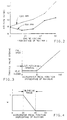
- FIG. 2 there is shown a graph of typical speed-load data for a crankcase-scavenged, two-stroke engine. This data was obtained by standard engine dynamometer measurements know to those skilled in the art of engine control.
- the desired engine air flow, to produce minimum exhaust gas hydrocarbons, is given as a function of the percentage of maximum engine loading, for engine speeds of 800 and 1200 RPM.
- the axis representing percentage of maximum engine loading is also equivalent to the percentage of maximum engine output power demanded by the operator. For an engine operating at 1200 RPM, the desired engine air flow monotonically increases as engine loading (or operator demand for engine output power) increases.
- the present invention is directed toward controlling the amounts of fuel and air delivered to a crankcase-scavenged, two-cycle engine to reduce hydrocarbon emissions, when the engine operation is near idle (800-1000 RPM), with light operator-induced loading (up to approximately 35 percent of maximum load). This is accomplished by restricting the mass of air per cylinder delivered to the engine to less than or equal to that delivered at unloaded engine idle, over the defined range of engine operation.
- Throttle plate 52 rotates about a throttle shaft 54, within intake manifold 20, to form a throttle valve for controlling the amount of air per cylinder delivered to engine 10.
- Accelerator pedal 56 functions as an operator-actuated control element, indicating the amount of engine output power demanded by the operator.
- a spring or other resilient means associated with accelerator pedal 56 for returning it to an initial position, once operator actuation ceases.
- Increased counterclockwise movement of accelerator pedal 56 about pivot pin 58 indicates an increased demand for engine output power.
- Link 68 Connecting accelerator pedal 56 to throttle plate 52 is a linkage assembly consisting of levers 60 and 62, along with links 64, 66, and 68.
- Link 68 being rigidly attached to throttle shaft 54, provides a means for rotating throttle plate 52 within intake manifold 20.
- Links 64 and 66 have a common pivot pin 70, with tang 72 projecting from link 64 into a slot 74 formed in link 66.
- Lever 60 connects accelerator pedal 56 with link 64, whilst lever 62 connects link 66 with link 68, each lever end forming a pivotal connection with the element connected.
- the throttle linkage assembly provides a means for operator control of the throttle valve formed by the throttle plate 52 in intake manifold 20.
- the initial position of accelerator pedal 56 corresponds to steady state condition of unloaded engine idle, with throttle plate 52 at its minimum idle setting for air flow through the throttle valve.
- accelerator pedal 56 As accelerator pedal 56 is moved from its initial position with increased operator demand for engine output, it rotates counterclockwise about pivot pin 58. This in turn pulls lever 60, causing link 64 to rotate clockwise about pivot pin 70.
- Link 64 rotates freely without affecting the movement of link 66, until tang 72 reaches the end of slot 74. Then tang 72 engages link 66, causing it to rotate in a clockwise direction about pivot pin 70, with any additional movement of the accelerator pedal 56.
- link 66 rotates in a clockwise direction
- lever 62 is pulled to rotate link 68 in a direction counterclockwise about the axis of throttle shaft 54. Since link 68 and throttle plate 52 are rigidly attached to shaft 54, counterclockwise movement of link 68 effects opening movement of throttle plate 52, producing increased air flow to the engine 10.
- the linkage assembly provides for an interval of lost motion with respect to initial movement of the accelerator pedal 56. Over this interval of lost motion, movement of the accelerator pedal 56 does not affect the opening of the throttle plate 52 and the air flow to the engine remains constant. As movement of the accelerator pedal 56 continues, the point is reached where tang 72 engages link 66, and throttle plate 52 is then opened. Slot 74 is preferably formed so that the accelerator pedal 56 can move approximately 30 percent of its full movement before tang 72 engages link 66, thereby effecting opening of throttle valve.
- intake manifold 20 is provided with a passage 76, which bypasses the throttle valve formed by throttle plate 52 in manifold 20.
- a bypass valve 78 for restricting airflow.
- Computer 48 remotely controls the position of bypass valve 78 by sending an appropriate VALVE SIGNAL to an electric solenoid 82, which actuates the bypass valve 78 and is mounted on intake manifold 20.
- bypass valve 78 is positioned to be one-half open, with the idle setting of throttle plate 52 adjusted so that the total mass air flow through intake manifold 20 corresponds to that value which produces minimum hydrocarbon emissions (see Figure 2).
- the combination of the bypass valve 78 and the wasted-motion throttle linkage provides the means for reducing the delivered mass air per cylinder to conform to the pre-defined schedule for minimum hydrocarbon emissions at engine speeds near idle (800-1000 RPM), with light operator loading (up to approximately 35 percent of maximum load).
- An additional computer input is provided by a potentiometer 84, which senses the position of the accelerator pedal 56 and supplies a representative signal PED to computer 48.
- This PED signal indicates the percentage of engine output power demanded by the operator, or equivalently, the percentage of operator-induced engine loading.
- computer 48 Based on the position of the accelerator pedal, as indicated by the PED signal, computer 48 adjusts the position of bypass valve 78 to reduce the mass of air per cylinder flowing to engine 10 in accordance with the schedule for minimum exhaust gas hydrocarbons as defined by data presented in Figure 2.
- Computer 48 is informed that the end of the lost-motion interval of the throttle linkage has been reached when the PED signal indicates that the accelerator pedal has moved 30 percent of its full range of movement. Further movement of the accelerator pedal in the direction of increased engine loading, results in opening of throttle plate 46 to increase the mass air flow to engine 10.
- the PED signal is also used by computer 48 in computing the amount of fuel per cylinder to supply to engine 10.
- the total fuel per cylinder delivered to the engine is based upon both the an indication of the mass air per cylinder actually delivered to engine 10 and the indicated engine output power demanded by the operator.
- the fuel per cylinder is computed according to the relationship where, FCOD is the fuel per cylinder based upon operator demand for output power, as indicated by PED; FCMA is the fuel per cylinder based upon the actual air mass per cylinder delivered to the engine, as derived from MAF; and K is a blending variable which is a function of engine speed and the accelerator pedal position as indicated by PED.
- Figure 4 illustrates a graph of the variable K as a function of the percentage of maximum accelerator pedal position.
- K acts as a blending variable to assure a continuous delivery of fuel and smooth engine operation, as engine operation moves to the region where the delivered mass air per cylinder increases rather than decreases with increasing operator demand for output power.
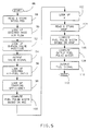
- FIG. 5 there is shown a flow diagram illustrating the operation of computer 48 in controlling engine 10 according to the principles of the present invention.
- the programming of computer 48 to implement the illustrated steps should be clear to any programmer skilled in the art of engine control.
- the routine begins at step 86 and is executed by computer 48 at regular intervals of approximately 6 milliseconds.
- the computer 48 determines and stores values of the current engine operating speed in RPM and the accelerator pedal position PED.
- the program looks up the desired mass air flow DMAF for minimum hydrocarbons from a table stored in memory using values for engine speed and PED stored in the previous step.
- the values for desired mass airflow are obtained from measured engine speed-load curves such as presented in Figure 2. For speeds near engine idle and light operator-induced loading, the desired air flow will be less than that flowing at unloaded engine idle for minimum hydrocarbons as described previously.
- step 92 the position for bypass valve 78 is looked up in a table stored in memory as a function of the desired air flow found in the previous step 90.
- the program outputs a value of VALVE SIGNAL, which corresponds to the bypass valve position determined at step 92.
- the air flow to the engine is adjusted to the value scheduled to minimize hydrocarbons in the exhaust gas of engine 10.
- step 96 the program looks up the desired air-fuel ratio (A/F) in a table stored in computer memory, using values for the accelerator pedal position PED and the speed of the engine. Values in the air-fuel ratio table are determined by standard engine dynamometer measurements at different speeds, and different engine loading corresponding to that desired by operator movement of the accelerator pedal.
- the program looks up a value for trapping efficiency (TE) in another table stored in memory, using values for the engine speed, and the desired mass air flow found previously in step 90.
- the trapping efficiency represents that percentage of the mass air inducted into crankcase chamber 18, which is transferred and captured within combustion chamber 38, after closure of air inlet port 32 and exhaust port 26. Values for trapping efficiency are determined by measurement, and are a function of the mass of air being transferred from the crankcase chamber 18, and the engine speed which determines the time available for the air to pass through inlet port 32 or be lost out of exhaust port 24.
- the injector fuel pulse width (FPWOD) based upon accelerator pedal position PED (or equivalent ly operator demand for engine output power) is computed according to the following:
- the value for the blending variable K is looked up in a table stored in memory, using values for the accelerator pedal position PED and the engine speed. For values of engine speed near idle, in the range from 800 to 1000 RPM, the value of K varies with accelerator pedal position PED, as shown previously in Figure 4.
- the actual mass air per cylinder (AMAF) flowing into the engine 10 is derived from the MAF input signal and stored in memory. This value for AMAF is then used in the next program step 106 to compute FPWMAF, the injector fuel pulse width based upon the actual mass air per cylinder, according to the following:
- the final output fuel pulse width FPW is computed as a function of both FPWOD and FPWMAF, determined at steps 100 and 106, respectively, according to
- the program outputs FUEL SIGNAL to fuel injector 36, consisting of a pulse having a width equal to FPW as computed in step 108.
- FUEL SIGNAL to fuel injector 36, consisting of a pulse having a width equal to FPW as computed in step 108.
- step 112 the routine is exited, so that other engine control functions may be performed by computer 44.
- Another embodiment of the present invention is possible using the lost motion throttle linkage, without bypass passage 76 and the solenoid-activated bypass valve 78 being present in intake manifold 20.
- the delivered air per cylinder during the lost-motion interval of the throttle linkage, will remain constant ratherthan decreasing according to minimum hydrocarbon schedule.
- the delivery air per cylinder constant, rather than reducing it over the lost-motion interval, the reduction in exhaust gas hydrocarbons will be less, but the emission control system is simplified without the bypass valve and associated positioning control.
Landscapes
- Engineering & Computer Science (AREA)
- Chemical & Material Sciences (AREA)
- Combustion & Propulsion (AREA)
- Mechanical Engineering (AREA)
- General Engineering & Computer Science (AREA)
- Electrical Control Of Air Or Fuel Supplied To Internal-Combustion Engine (AREA)
- Control Of Throttle Valves Provided In The Intake System Or In The Exhaust System (AREA)
Claims (6)
wobei TZFA Kraftstoff pro Zylinder aufgrund der Fahreranforderung nach Motorleistungsabgabe und Motordrehzahl, TZLM Kraftstoff pro Zylinder aufgrund der in den Motor strömenden Luftmasse pro Zylinder und der Motordrehzahl und Keine Mischvariable ist, die von der Drehzahl abhängt, dabei einen Wert 1 bei unbelastetem Motorbetrieb innerhalb eines bestimmten Bereichs von leerlaufnahen Motordrehzahlen hat und in ihrem Wert auf 0 abnimmt, wenn die Anforderung des Fahrers nach Motorleistungsabgabe den Motorbetrieb außerhalb des vorbestimmten Bereichs bringt.
Applications Claiming Priority (2)
| Application Number | Priority Date | Filing Date | Title |
|---|---|---|---|
| US07/393,189 US4932371A (en) | 1989-08-14 | 1989-08-14 | Emission control system for a crankcase scavenged two-stroke engine operating near idle |
| US393189 | 1989-08-14 |
Publications (4)
| Publication Number | Publication Date |
|---|---|
| EP0413432A2 EP0413432A2 (de) | 1991-02-20 |
| EP0413432A3 EP0413432A3 (en) | 1991-05-02 |
| EP0413432B1 true EP0413432B1 (de) | 1993-04-28 |
| EP0413432B2 EP0413432B2 (de) | 1994-12-07 |
Family
ID=23553648
Family Applications (1)
| Application Number | Title | Priority Date | Filing Date |
|---|---|---|---|
| EP90307616A Expired - Lifetime EP0413432B2 (de) | 1989-08-14 | 1990-07-11 | Schadstoffregelungssystem für einen Zweitaktmotor mit Kurbelgehäusespülung beim leerlaufnahen Bereich |
Country Status (5)
| Country | Link |
|---|---|
| US (1) | US4932371A (de) |
| EP (1) | EP0413432B2 (de) |
| JP (1) | JPH0396631A (de) |
| CA (1) | CA2017241A1 (de) |
| DE (1) | DE69001468T2 (de) |
Cited By (1)
| Publication number | Priority date | Publication date | Assignee | Title |
|---|---|---|---|---|
| EP4414550A3 (de) * | 2018-08-02 | 2025-04-02 | Husqvarna AB | Zweitakt-motorsteuerung |
Families Citing this family (15)
| Publication number | Priority date | Publication date | Assignee | Title |
|---|---|---|---|---|
| MX172111B (es) * | 1989-02-17 | 1993-12-03 | Orbital Eng Pty | Sistema de suministro de aire para un motor de combustion interna |
| JPH0385346A (ja) * | 1989-08-29 | 1991-04-10 | Fuji Heavy Ind Ltd | 2サイクルエンジンのアイドリング回転数制御装置 |
| PH30377A (en) * | 1992-02-11 | 1997-04-15 | Orbital Eng Pty | Air fuel ratio control |
| US5257607A (en) * | 1992-10-23 | 1993-11-02 | Outboard Marine Corporation | Fuel injected, two-stroke internal combustion engine |
| US5282448A (en) * | 1993-03-01 | 1994-02-01 | General Motors Corporation | Fuel control of a two-stroke engine with over-center throttle body |
| BR9407115A (pt) * | 1993-06-30 | 1996-09-03 | Orbital Eng Pty | Sistemas de suprimentro de ar de motor |
| JP3195147B2 (ja) * | 1993-11-27 | 2001-08-06 | 本田技研工業株式会社 | 火花点火式2サイクルエンジンの絞り弁制御装置 |
| JPH07189875A (ja) * | 1993-12-28 | 1995-07-28 | Yamaha Motor Co Ltd | 2サイクルエンジンの燃料噴射装置 |
| JPH0835438A (ja) * | 1994-07-25 | 1996-02-06 | Hitachi Ltd | エンジンパワートレインの制御方法 |
| JPH08291780A (ja) * | 1995-04-20 | 1996-11-05 | Yamaha Motor Co Ltd | 2サイクルエンジンにおける燃料噴射方法及び燃料噴射装置付き2サイクルエンジン |
| US5720254A (en) * | 1995-05-19 | 1998-02-24 | Yamaha Hatsudoki Kabushiki Kaisha | Fuel injection system for engine |
| AUPO094996A0 (en) * | 1996-07-10 | 1996-08-01 | Orbital Engine Company (Australia) Proprietary Limited | Engine fuelling rate control |
| JP3024072B2 (ja) * | 1996-10-17 | 2000-03-21 | 財団法人石油産業活性化センター | 層状掃気2サイクルエンジン |
| JP6330770B2 (ja) * | 2015-09-25 | 2018-05-30 | マツダ株式会社 | ターボ過給機付エンジンの制御装置 |
| CN110192015A (zh) * | 2017-01-18 | 2019-08-30 | 本田技研工业株式会社 | 二冲程发动机 |
Family Cites Families (14)
| Publication number | Priority date | Publication date | Assignee | Title |
|---|---|---|---|---|
| US2332916A (en) * | 1942-08-26 | 1943-10-26 | Gen Electric | Internal combustion engine arrangement |
| GB1591050A (en) * | 1976-08-25 | 1981-06-10 | Onishi S | Internal combustion engine |
| JPS5926787B2 (ja) * | 1978-02-09 | 1984-06-30 | トヨタ自動車株式会社 | 活性熱雰囲気燃焼2サイクル内燃機関の排気ガス再循環装置 |
| JPS5970853A (ja) * | 1982-10-18 | 1984-04-21 | Hitachi Ltd | 自動車用エンジンの制御装置 |
| JPS59158328A (ja) * | 1983-02-26 | 1984-09-07 | Nissan Motor Co Ltd | 内燃機関 |
| DE3341720C2 (de) * | 1983-11-18 | 1987-01-15 | Bayerische Motoren Werke AG, 8000 München | Vorrichtung zur Steuerung einer Brennkraftmaschine |
| KR890000500B1 (ko) * | 1983-11-21 | 1989-03-20 | 가부시기가이샤 히다찌세이사꾸쇼 | 내연기관의 공연비 제어장치 |
| JPS60178940A (ja) * | 1984-02-24 | 1985-09-12 | Nissan Motor Co Ltd | 内燃機関の吸入空気制御装置 |
| JPS61152935A (ja) * | 1984-12-26 | 1986-07-11 | Fuji Heavy Ind Ltd | 空燃比制御装置 |
| JPS6388231A (ja) * | 1986-09-30 | 1988-04-19 | Sanshin Ind Co Ltd | 船外機エンジンの速度制御装置 |
| US4840148A (en) * | 1987-09-10 | 1989-06-20 | Brunswick Corporation | Two cycle engine with low pressure crankcase fuel injection |
| DE3728118A1 (de) * | 1987-08-22 | 1989-03-02 | Pierburg Gmbh | Verfahren zur steuerung der einspritzphase einer elektronischen brennstoffeinspritzung |
| US4768494A (en) * | 1987-09-09 | 1988-09-06 | Brunswick Corporation | Idling system for multi-cylinder two-stroke engine |
| US4825821A (en) * | 1988-04-20 | 1989-05-02 | Outboard Marine Corporation | Carburetor pulse-back damping system for 2-cycle internal combustion engine |
-
1989
- 1989-08-14 US US07/393,189 patent/US4932371A/en not_active Expired - Lifetime
-
1990
- 1990-05-22 CA CA002017241A patent/CA2017241A1/en not_active Abandoned
- 1990-07-11 DE DE9090307616T patent/DE69001468T2/de not_active Expired - Lifetime
- 1990-07-11 EP EP90307616A patent/EP0413432B2/de not_active Expired - Lifetime
- 1990-08-14 JP JP2215681A patent/JPH0396631A/ja active Pending
Cited By (1)
| Publication number | Priority date | Publication date | Assignee | Title |
|---|---|---|---|---|
| EP4414550A3 (de) * | 2018-08-02 | 2025-04-02 | Husqvarna AB | Zweitakt-motorsteuerung |
Also Published As
| Publication number | Publication date |
|---|---|
| AU5976090A (en) | 1991-02-14 |
| CA2017241A1 (en) | 1991-02-14 |
| EP0413432A2 (de) | 1991-02-20 |
| DE69001468D1 (de) | 1993-06-03 |
| US4932371A (en) | 1990-06-12 |
| JPH0396631A (ja) | 1991-04-22 |
| AU612081B2 (en) | 1991-06-27 |
| EP0413432B2 (de) | 1994-12-07 |
| DE69001468T2 (de) | 1993-08-12 |
| EP0413432A3 (en) | 1991-05-02 |
Similar Documents
| Publication | Publication Date | Title |
|---|---|---|
| EP0413432B1 (de) | Schadstoffregelungssystem für einen Zweitaktmotor mit Kurbelgehäusespülung beim leerlaufnahen Bereich | |
| EP0239095B1 (de) | Methode und System zur Steuerung von Innen-Verbrennungsmaschinen | |
| US4924840A (en) | Fast response exhaust gas recirculation (EGR) system | |
| US4403584A (en) | Method and apparatus for optimum control for internal combustion engines | |
| US7369934B2 (en) | Predictive engine combustion management | |
| EP0206517B1 (de) | Methode zur Steuerung der Kraftstoffversorgung und Kraftstoffeinspritzungsgerät | |
| US4434769A (en) | Deceleration fuel cut device for internal combustion engines | |
| EP0831223A3 (de) | Steuervorrichtung für eine Brennkraftmaschine mittels eines Verfahrens zur Steuerung erstens der Luft- und zweitens der Kraftstoffmenge | |
| US5094206A (en) | Method for controlling a crankcase scavenged two-stroke engine during deceleration fuel cut-off | |
| US4522179A (en) | Engine speed detecting system for multiple-displacement engine | |
| US5448974A (en) | Engine output control | |
| EP0071272A2 (de) | Durchflussregler für eine spiralige Einlassöffnung einer Dieselmaschine | |
| US4955341A (en) | Idle control system for a crankcase scavenged two-stroke engine | |
| JP3445500B2 (ja) | 電制スロットル式内燃機関のアイドル回転学習制御装置 | |
| US4458651A (en) | Electronically controlled fuel injection system for an internal combustion engine of an automotive vehicle | |
| US5988139A (en) | Method and apparatus for controlling an internal combustion engine | |
| EP0162353B1 (de) | Ansaugsystem für eine Brennkraftmaschine | |
| EP0434111B1 (de) | Methode und Vorrichtung zur Regelung des Kraftstoffeinspritzzeitpunkts | |
| US5282448A (en) | Fuel control of a two-stroke engine with over-center throttle body | |
| US6257200B1 (en) | Engine control strategy | |
| GB2235494A (en) | Braking a two-stroke engine | |
| CA1266903A (en) | Control system for internal combustion engines | |
| JP2813226B2 (ja) | 2サイクルエンジンの燃料噴射装置 | |
| JP2591261B2 (ja) | 内燃機関の燃料供給方法 | |
| JPH073199B2 (ja) | 可変バルブタイミング機関の制御方法 |
Legal Events
| Date | Code | Title | Description |
|---|---|---|---|
| PUAI | Public reference made under article 153(3) epc to a published international application that has entered the european phase |
Free format text: ORIGINAL CODE: 0009012 |
|
| AK | Designated contracting states |
Kind code of ref document: A2 Designated state(s): DE FR GB IT |
|
| PUAL | Search report despatched |
Free format text: ORIGINAL CODE: 0009013 |
|
| AK | Designated contracting states |
Kind code of ref document: A3 Designated state(s): DE FR GB IT |
|
| RHK1 | Main classification (correction) |
Ipc: F02D 41/10 |
|
| 17P | Request for examination filed |
Effective date: 19910608 |
|
| 17Q | First examination report despatched |
Effective date: 19920217 |
|
| GRAA | (expected) grant |
Free format text: ORIGINAL CODE: 0009210 |
|
| ITF | It: translation for a ep patent filed | ||
| AK | Designated contracting states |
Kind code of ref document: B1 Designated state(s): DE FR GB IT |
|
| REF | Corresponds to: |
Ref document number: 69001468 Country of ref document: DE Date of ref document: 19930603 |
|
| ET | Fr: translation filed | ||
| PGFP | Annual fee paid to national office [announced via postgrant information from national office to epo] |
Ref country code: FR Payment date: 19930730 Year of fee payment: 4 |
|
| ITTA | It: last paid annual fee | ||
| PGFP | Annual fee paid to national office [announced via postgrant information from national office to epo] |
Ref country code: DE Payment date: 19930826 Year of fee payment: 4 |
|
| PLBI | Opposition filed |
Free format text: ORIGINAL CODE: 0009260 |
|
| 26 | Opposition filed |
Opponent name: GENERAL MOTORS CORPORATION Effective date: 19940114 |
|
| ITF | It: translation for a ep patent filed | ||
| PUAH | Patent maintained in amended form |
Free format text: ORIGINAL CODE: 0009272 |
|
| STAA | Information on the status of an ep patent application or granted ep patent |
Free format text: STATUS: PATENT MAINTAINED AS AMENDED |
|
| 27A | Patent maintained in amended form |
Effective date: 19941207 |
|
| AK | Designated contracting states |
Kind code of ref document: B2 Designated state(s): DE FR GB IT |
|
| PG25 | Lapsed in a contracting state [announced via postgrant information from national office to epo] |
Ref country code: DE Effective date: 19950308 |
|
| EN3 | Fr: translation not filed ** decision concerning opposition | ||
| PG25 | Lapsed in a contracting state [announced via postgrant information from national office to epo] |
Ref country code: FR Effective date: 19950505 |
|
| REG | Reference to a national code |
Ref country code: FR Ref legal event code: ST |
|
| PGFP | Annual fee paid to national office [announced via postgrant information from national office to epo] |
Ref country code: GB Payment date: 20010621 Year of fee payment: 12 |
|
| REG | Reference to a national code |
Ref country code: GB Ref legal event code: IF02 |
|
| PG25 | Lapsed in a contracting state [announced via postgrant information from national office to epo] |
Ref country code: GB Free format text: LAPSE BECAUSE OF NON-PAYMENT OF DUE FEES Effective date: 20020711 |
|
| GBPC | Gb: european patent ceased through non-payment of renewal fee |
Effective date: 20020711 |
|
| PG25 | Lapsed in a contracting state [announced via postgrant information from national office to epo] |
Ref country code: IT Free format text: LAPSE BECAUSE OF NON-PAYMENT OF DUE FEES;WARNING: LAPSES OF ITALIAN PATENTS WITH EFFECTIVE DATE BEFORE 2007 MAY HAVE OCCURRED AT ANY TIME BEFORE 2007. THE CORRECT EFFECTIVE DATE MAY BE DIFFERENT FROM THE ONE RECORDED. Effective date: 20050711 |
|
| PG25 | Lapsed in a contracting state [announced via postgrant information from national office to epo] |
Ref country code: FR Effective date: 19940731 |