EP0413480B1 - Electrode pour le dégagement d'hydrogène présentant une haute durabilité et stabilité - Google Patents
Electrode pour le dégagement d'hydrogène présentant une haute durabilité et stabilité Download PDFInfo
- Publication number
- EP0413480B1 EP0413480B1 EP90308567A EP90308567A EP0413480B1 EP 0413480 B1 EP0413480 B1 EP 0413480B1 EP 90308567 A EP90308567 A EP 90308567A EP 90308567 A EP90308567 A EP 90308567A EP 0413480 B1 EP0413480 B1 EP 0413480B1
- Authority
- EP
- European Patent Office
- Prior art keywords
- coating
- titanium
- ray diffraction
- zirconium
- electrode
- Prior art date
- Legal status (The legal status is an assumption and is not a legal conclusion. Google has not performed a legal analysis and makes no representation as to the accuracy of the status listed.)
- Expired - Lifetime
Links
- 238000000576 coating method Methods 0.000 claims description 108
- 239000011248 coating agent Substances 0.000 claims description 103
- PXHVJJICTQNCMI-UHFFFAOYSA-N Nickel Chemical compound [Ni] PXHVJJICTQNCMI-UHFFFAOYSA-N 0.000 claims description 85
- RTAQQCXQSZGOHL-UHFFFAOYSA-N Titanium Chemical compound [Ti] RTAQQCXQSZGOHL-UHFFFAOYSA-N 0.000 claims description 80
- 239000010936 titanium Substances 0.000 claims description 79
- 229910052719 titanium Inorganic materials 0.000 claims description 77
- QCWXUUIWCKQGHC-UHFFFAOYSA-N Zirconium Chemical compound [Zr] QCWXUUIWCKQGHC-UHFFFAOYSA-N 0.000 claims description 64
- 229910052726 zirconium Inorganic materials 0.000 claims description 59
- 238000002441 X-ray diffraction Methods 0.000 claims description 42
- 229910052759 nickel Inorganic materials 0.000 claims description 41
- 229910052751 metal Inorganic materials 0.000 claims description 36
- 239000002184 metal Substances 0.000 claims description 36
- 239000000758 substrate Substances 0.000 claims description 33
- 239000010941 cobalt Substances 0.000 claims description 30
- 229910017052 cobalt Inorganic materials 0.000 claims description 30
- GUTLYIVDDKVIGB-UHFFFAOYSA-N cobalt atom Chemical compound [Co] GUTLYIVDDKVIGB-UHFFFAOYSA-N 0.000 claims description 30
- 229910000480 nickel oxide Inorganic materials 0.000 claims description 28
- GNRSAWUEBMWBQH-UHFFFAOYSA-N oxonickel Chemical compound [Ni]=O GNRSAWUEBMWBQH-UHFFFAOYSA-N 0.000 claims description 18
- 229910044991 metal oxide Inorganic materials 0.000 claims description 15
- 150000004706 metal oxides Chemical class 0.000 claims description 15
- 230000003647 oxidation Effects 0.000 claims description 15
- 238000007254 oxidation reaction Methods 0.000 claims description 15
- 239000000463 material Substances 0.000 claims description 8
- 150000002739 metals Chemical class 0.000 claims description 8
- 229910000990 Ni alloy Inorganic materials 0.000 claims description 5
- 239000010935 stainless steel Substances 0.000 claims description 5
- 229910001220 stainless steel Inorganic materials 0.000 claims description 5
- 229910001566 austenite Inorganic materials 0.000 claims description 4
- 239000008187 granular material Substances 0.000 description 37
- 238000000034 method Methods 0.000 description 35
- UFHFLCQGNIYNRP-UHFFFAOYSA-N Hydrogen Chemical compound [H][H] UFHFLCQGNIYNRP-UHFFFAOYSA-N 0.000 description 29
- 239000001257 hydrogen Substances 0.000 description 29
- 229910052739 hydrogen Inorganic materials 0.000 description 29
- 238000005868 electrolysis reaction Methods 0.000 description 25
- 238000005507 spraying Methods 0.000 description 22
- 239000000203 mixture Substances 0.000 description 21
- 238000005469 granulation Methods 0.000 description 18
- 230000003179 granulation Effects 0.000 description 18
- 230000000694 effects Effects 0.000 description 17
- XKRFYHLGVUSROY-UHFFFAOYSA-N Argon Chemical compound [Ar] XKRFYHLGVUSROY-UHFFFAOYSA-N 0.000 description 16
- IJGRMHOSHXDMSA-UHFFFAOYSA-N Atomic nitrogen Chemical compound N#N IJGRMHOSHXDMSA-UHFFFAOYSA-N 0.000 description 16
- 239000007789 gas Substances 0.000 description 14
- VYZAMTAEIAYCRO-UHFFFAOYSA-N Chromium Chemical compound [Cr] VYZAMTAEIAYCRO-UHFFFAOYSA-N 0.000 description 12
- HEMHJVSKTPXQMS-UHFFFAOYSA-M Sodium hydroxide Chemical compound [OH-].[Na+] HEMHJVSKTPXQMS-UHFFFAOYSA-M 0.000 description 12
- 239000011651 chromium Substances 0.000 description 12
- 229910052804 chromium Inorganic materials 0.000 description 12
- 239000007921 spray Substances 0.000 description 11
- XLYOFNOQVPJJNP-UHFFFAOYSA-N water Substances O XLYOFNOQVPJJNP-UHFFFAOYSA-N 0.000 description 11
- 239000002245 particle Substances 0.000 description 9
- 239000000725 suspension Substances 0.000 description 9
- 229910052786 argon Inorganic materials 0.000 description 8
- 230000015572 biosynthetic process Effects 0.000 description 8
- 229910052757 nitrogen Inorganic materials 0.000 description 8
- 239000000243 solution Substances 0.000 description 8
- 239000000126 substance Substances 0.000 description 8
- GWEVSGVZZGPLCZ-UHFFFAOYSA-N Titan oxide Chemical compound O=[Ti]=O GWEVSGVZZGPLCZ-UHFFFAOYSA-N 0.000 description 7
- RVTZCBVAJQQJTK-UHFFFAOYSA-N oxygen(2-);zirconium(4+) Chemical compound [O-2].[O-2].[Zr+4] RVTZCBVAJQQJTK-UHFFFAOYSA-N 0.000 description 7
- 238000007750 plasma spraying Methods 0.000 description 7
- 230000002035 prolonged effect Effects 0.000 description 7
- 150000003839 salts Chemical class 0.000 description 7
- OGIDPMRJRNCKJF-UHFFFAOYSA-N titanium oxide Inorganic materials [Ti]=O OGIDPMRJRNCKJF-UHFFFAOYSA-N 0.000 description 7
- 229910001928 zirconium oxide Inorganic materials 0.000 description 7
- FAPWRFPIFSIZLT-UHFFFAOYSA-M Sodium chloride Chemical compound [Na+].[Cl-] FAPWRFPIFSIZLT-UHFFFAOYSA-M 0.000 description 6
- 229910000428 cobalt oxide Inorganic materials 0.000 description 6
- IVMYJDGYRUAWML-UHFFFAOYSA-N cobalt(ii) oxide Chemical compound [Co]=O IVMYJDGYRUAWML-UHFFFAOYSA-N 0.000 description 6
- 150000001875 compounds Chemical class 0.000 description 6
- 230000007423 decrease Effects 0.000 description 6
- 238000002844 melting Methods 0.000 description 6
- 230000008018 melting Effects 0.000 description 6
- 239000000843 powder Substances 0.000 description 6
- 239000006104 solid solution Substances 0.000 description 6
- 239000007864 aqueous solution Substances 0.000 description 5
- 239000011230 binding agent Substances 0.000 description 5
- 239000003795 chemical substances by application Substances 0.000 description 5
- 238000004090 dissolution Methods 0.000 description 5
- 239000012456 homogeneous solution Substances 0.000 description 5
- 238000007747 plating Methods 0.000 description 5
- 230000009467 reduction Effects 0.000 description 5
- QAOWNCQODCNURD-UHFFFAOYSA-N Sulfuric acid Chemical compound OS(O)(=O)=O QAOWNCQODCNURD-UHFFFAOYSA-N 0.000 description 4
- 239000003513 alkali Substances 0.000 description 4
- -1 alkyl aryl phosphates Chemical class 0.000 description 4
- 238000006243 chemical reaction Methods 0.000 description 4
- 239000002270 dispersing agent Substances 0.000 description 4
- 239000007788 liquid Substances 0.000 description 4
- 239000011369 resultant mixture Substances 0.000 description 4
- 241000894007 species Species 0.000 description 4
- 239000007858 starting material Substances 0.000 description 4
- WSFSSNUMVMOOMR-UHFFFAOYSA-N Formaldehyde Chemical compound O=C WSFSSNUMVMOOMR-UHFFFAOYSA-N 0.000 description 3
- 239000012670 alkaline solution Substances 0.000 description 3
- 125000004429 atom Chemical group 0.000 description 3
- QVGXLLKOCUKJST-UHFFFAOYSA-N atomic oxygen Chemical compound [O] QVGXLLKOCUKJST-UHFFFAOYSA-N 0.000 description 3
- 238000001816 cooling Methods 0.000 description 3
- 238000009713 electroplating Methods 0.000 description 3
- 238000010348 incorporation Methods 0.000 description 3
- 238000005259 measurement Methods 0.000 description 3
- 238000002156 mixing Methods 0.000 description 3
- 230000001590 oxidative effect Effects 0.000 description 3
- 239000001301 oxygen Substances 0.000 description 3
- 229910052760 oxygen Inorganic materials 0.000 description 3
- 239000011780 sodium chloride Substances 0.000 description 3
- 239000004094 surface-active agent Substances 0.000 description 3
- 230000004580 weight loss Effects 0.000 description 3
- 229920002134 Carboxymethyl cellulose Polymers 0.000 description 2
- QUSNBJAOOMFDIB-UHFFFAOYSA-N Ethylamine Chemical compound CCN QUSNBJAOOMFDIB-UHFFFAOYSA-N 0.000 description 2
- 229920000084 Gum arabic Polymers 0.000 description 2
- XEEYBQQBJWHFJM-UHFFFAOYSA-N Iron Chemical compound [Fe] XEEYBQQBJWHFJM-UHFFFAOYSA-N 0.000 description 2
- ISWSIDIOOBJBQZ-UHFFFAOYSA-N Phenol Chemical compound OC1=CC=CC=C1 ISWSIDIOOBJBQZ-UHFFFAOYSA-N 0.000 description 2
- 241000978776 Senegalia senegal Species 0.000 description 2
- VYPSYNLAJGMNEJ-UHFFFAOYSA-N Silicium dioxide Chemical compound O=[Si]=O VYPSYNLAJGMNEJ-UHFFFAOYSA-N 0.000 description 2
- CDBYLPFSWZWCQE-UHFFFAOYSA-L Sodium Carbonate Chemical compound [Na+].[Na+].[O-]C([O-])=O CDBYLPFSWZWCQE-UHFFFAOYSA-L 0.000 description 2
- XLOMVQKBTHCTTD-UHFFFAOYSA-N Zinc monoxide Chemical compound [Zn]=O XLOMVQKBTHCTTD-UHFFFAOYSA-N 0.000 description 2
- 238000010521 absorption reaction Methods 0.000 description 2
- 239000000205 acacia gum Substances 0.000 description 2
- 235000010489 acacia gum Nutrition 0.000 description 2
- 150000001242 acetic acid derivatives Chemical class 0.000 description 2
- 239000011149 active material Substances 0.000 description 2
- 230000002411 adverse Effects 0.000 description 2
- 230000002421 anti-septic effect Effects 0.000 description 2
- 239000012298 atmosphere Substances 0.000 description 2
- 230000008901 benefit Effects 0.000 description 2
- 238000001354 calcination Methods 0.000 description 2
- 239000001768 carboxy methyl cellulose Substances 0.000 description 2
- 235000010948 carboxy methyl cellulose Nutrition 0.000 description 2
- 239000008112 carboxymethyl-cellulose Substances 0.000 description 2
- 230000003197 catalytic effect Effects 0.000 description 2
- 150000003841 chloride salts Chemical class 0.000 description 2
- 239000011247 coating layer Substances 0.000 description 2
- 230000000052 comparative effect Effects 0.000 description 2
- 238000005260 corrosion Methods 0.000 description 2
- 230000007797 corrosion Effects 0.000 description 2
- 239000013078 crystal Substances 0.000 description 2
- 238000002425 crystallisation Methods 0.000 description 2
- 230000008025 crystallization Effects 0.000 description 2
- 238000010494 dissociation reaction Methods 0.000 description 2
- 230000005593 dissociations Effects 0.000 description 2
- 238000001035 drying Methods 0.000 description 2
- 239000003792 electrolyte Substances 0.000 description 2
- 239000008151 electrolyte solution Substances 0.000 description 2
- 230000001747 exhibiting effect Effects 0.000 description 2
- 238000010285 flame spraying Methods 0.000 description 2
- 230000004907 flux Effects 0.000 description 2
- 150000004675 formic acid derivatives Chemical class 0.000 description 2
- 150000002431 hydrogen Chemical class 0.000 description 2
- 238000012423 maintenance Methods 0.000 description 2
- 238000004519 manufacturing process Methods 0.000 description 2
- 229920000609 methyl cellulose Polymers 0.000 description 2
- 239000001923 methylcellulose Substances 0.000 description 2
- 235000010981 methylcellulose Nutrition 0.000 description 2
- 239000012768 molten material Substances 0.000 description 2
- 150000002823 nitrates Chemical class 0.000 description 2
- 231100000989 no adverse effect Toxicity 0.000 description 2
- 150000003891 oxalate salts Chemical class 0.000 description 2
- BASFCYQUMIYNBI-UHFFFAOYSA-N platinum Chemical compound [Pt] BASFCYQUMIYNBI-UHFFFAOYSA-N 0.000 description 2
- 230000008569 process Effects 0.000 description 2
- MGAXYKDBRBNWKT-UHFFFAOYSA-N (5-oxooxolan-2-yl)methyl 4-methylbenzenesulfonate Chemical compound C1=CC(C)=CC=C1S(=O)(=O)OCC1OC(=O)CC1 MGAXYKDBRBNWKT-UHFFFAOYSA-N 0.000 description 1
- RYGMFSIKBFXOCR-UHFFFAOYSA-N Copper Chemical compound [Cu] RYGMFSIKBFXOCR-UHFFFAOYSA-N 0.000 description 1
- 239000001856 Ethyl cellulose Substances 0.000 description 1
- ZZSNKZQZMQGXPY-UHFFFAOYSA-N Ethyl cellulose Chemical compound CCOCC1OC(OC)C(OCC)C(OCC)C1OC1C(O)C(O)C(OC)C(CO)O1 ZZSNKZQZMQGXPY-UHFFFAOYSA-N 0.000 description 1
- ZOKXTWBITQBERF-UHFFFAOYSA-N Molybdenum Chemical compound [Mo] ZOKXTWBITQBERF-UHFFFAOYSA-N 0.000 description 1
- 229910019142 PO4 Inorganic materials 0.000 description 1
- 239000002202 Polyethylene glycol Substances 0.000 description 1
- 239000004372 Polyvinyl alcohol Substances 0.000 description 1
- DBMJMQXJHONAFJ-UHFFFAOYSA-M Sodium laurylsulphate Chemical compound [Na+].CCCCCCCCCCCCOS([O-])(=O)=O DBMJMQXJHONAFJ-UHFFFAOYSA-M 0.000 description 1
- WGLPBDUCMAPZCE-UHFFFAOYSA-N Trioxochromium Chemical compound O=[Cr](=O)=O WGLPBDUCMAPZCE-UHFFFAOYSA-N 0.000 description 1
- HCHKCACWOHOZIP-UHFFFAOYSA-N Zinc Chemical compound [Zn] HCHKCACWOHOZIP-UHFFFAOYSA-N 0.000 description 1
- DPXJVFZANSGRMM-UHFFFAOYSA-N acetic acid;2,3,4,5,6-pentahydroxyhexanal;sodium Chemical compound [Na].CC(O)=O.OCC(O)C(O)C(O)C(O)C=O DPXJVFZANSGRMM-UHFFFAOYSA-N 0.000 description 1
- 230000009471 action Effects 0.000 description 1
- 239000004480 active ingredient Substances 0.000 description 1
- 229910001508 alkali metal halide Inorganic materials 0.000 description 1
- 150000008045 alkali metal halides Chemical class 0.000 description 1
- 150000008055 alkyl aryl sulfonates Chemical class 0.000 description 1
- 229910052782 aluminium Inorganic materials 0.000 description 1
- XAGFODPZIPBFFR-UHFFFAOYSA-N aluminium Chemical compound [Al] XAGFODPZIPBFFR-UHFFFAOYSA-N 0.000 description 1
- PNEYBMLMFCGWSK-UHFFFAOYSA-N aluminium oxide Inorganic materials [O-2].[O-2].[O-2].[Al+3].[Al+3] PNEYBMLMFCGWSK-UHFFFAOYSA-N 0.000 description 1
- VBIXEXWLHSRNKB-UHFFFAOYSA-N ammonium oxalate Chemical compound [NH4+].[NH4+].[O-]C(=O)C([O-])=O VBIXEXWLHSRNKB-UHFFFAOYSA-N 0.000 description 1
- 238000004458 analytical method Methods 0.000 description 1
- 229940064004 antiseptic throat preparations Drugs 0.000 description 1
- NGPGDYLVALNKEG-UHFFFAOYSA-N azanium;azane;2,3,4-trihydroxy-4-oxobutanoate Chemical compound [NH4+].[NH4+].[O-]C(=O)C(O)C(O)C([O-])=O NGPGDYLVALNKEG-UHFFFAOYSA-N 0.000 description 1
- 239000002585 base Substances 0.000 description 1
- 150000004649 carbonic acid derivatives Chemical class 0.000 description 1
- 230000015556 catabolic process Effects 0.000 description 1
- 238000005341 cation exchange Methods 0.000 description 1
- 229910000423 chromium oxide Inorganic materials 0.000 description 1
- 238000005253 cladding Methods 0.000 description 1
- 238000002485 combustion reaction Methods 0.000 description 1
- 229910052802 copper Inorganic materials 0.000 description 1
- 239000010949 copper Substances 0.000 description 1
- 229910052593 corundum Inorganic materials 0.000 description 1
- 238000000354 decomposition reaction Methods 0.000 description 1
- 230000003247 decreasing effect Effects 0.000 description 1
- 238000006731 degradation reaction Methods 0.000 description 1
- 235000014113 dietary fatty acids Nutrition 0.000 description 1
- 239000012153 distilled water Substances 0.000 description 1
- 239000000428 dust Substances 0.000 description 1
- 235000010944 ethyl methyl cellulose Nutrition 0.000 description 1
- 238000004880 explosion Methods 0.000 description 1
- 239000000194 fatty acid Substances 0.000 description 1
- 229930195729 fatty acid Natural products 0.000 description 1
- 150000004665 fatty acids Chemical class 0.000 description 1
- 239000001307 helium Substances 0.000 description 1
- 229910052734 helium Inorganic materials 0.000 description 1
- SWQJXJOGLNCZEY-UHFFFAOYSA-N helium atom Chemical compound [He] SWQJXJOGLNCZEY-UHFFFAOYSA-N 0.000 description 1
- 150000004679 hydroxides Chemical class 0.000 description 1
- 239000011261 inert gas Substances 0.000 description 1
- 238000007603 infrared drying Methods 0.000 description 1
- 239000004615 ingredient Substances 0.000 description 1
- 239000003014 ion exchange membrane Substances 0.000 description 1
- 229910052742 iron Inorganic materials 0.000 description 1
- 230000007246 mechanism Effects 0.000 description 1
- 239000012528 membrane Substances 0.000 description 1
- 229920003087 methylethyl cellulose Polymers 0.000 description 1
- 239000010446 mirabilite Substances 0.000 description 1
- 229910052750 molybdenum Inorganic materials 0.000 description 1
- 239000011733 molybdenum Substances 0.000 description 1
- 229910000476 molybdenum oxide Inorganic materials 0.000 description 1
- 239000006199 nebulizer Substances 0.000 description 1
- BFDHFSHZJLFAMC-UHFFFAOYSA-L nickel(ii) hydroxide Chemical compound [OH-].[OH-].[Ni+2] BFDHFSHZJLFAMC-UHFFFAOYSA-L 0.000 description 1
- PQQKPALAQIIWST-UHFFFAOYSA-N oxomolybdenum Chemical compound [Mo]=O PQQKPALAQIIWST-UHFFFAOYSA-N 0.000 description 1
- 150000002989 phenols Chemical class 0.000 description 1
- 235000021317 phosphate Nutrition 0.000 description 1
- 229920001223 polyethylene glycol Polymers 0.000 description 1
- 239000011118 polyvinyl acetate Substances 0.000 description 1
- 229920002689 polyvinyl acetate Polymers 0.000 description 1
- 229920002451 polyvinyl alcohol Polymers 0.000 description 1
- 239000002994 raw material Substances 0.000 description 1
- 238000011160 research Methods 0.000 description 1
- 238000005096 rolling process Methods 0.000 description 1
- 238000004904 shortening Methods 0.000 description 1
- 239000000377 silicon dioxide Substances 0.000 description 1
- 235000012239 silicon dioxide Nutrition 0.000 description 1
- 239000000344 soap Substances 0.000 description 1
- 229910000029 sodium carbonate Inorganic materials 0.000 description 1
- 235000019812 sodium carboxymethyl cellulose Nutrition 0.000 description 1
- GCLGEJMYGQKIIW-UHFFFAOYSA-H sodium hexametaphosphate Chemical compound [Na]OP1(=O)OP(=O)(O[Na])OP(=O)(O[Na])OP(=O)(O[Na])OP(=O)(O[Na])OP(=O)(O[Na])O1 GCLGEJMYGQKIIW-UHFFFAOYSA-H 0.000 description 1
- 235000019982 sodium hexametaphosphate Nutrition 0.000 description 1
- 235000019333 sodium laurylsulphate Nutrition 0.000 description 1
- PFUVRDFDKPNGAV-UHFFFAOYSA-N sodium peroxide Chemical compound [Na+].[Na+].[O-][O-] PFUVRDFDKPNGAV-UHFFFAOYSA-N 0.000 description 1
- RSIJVJUOQBWMIM-UHFFFAOYSA-L sodium sulfate decahydrate Chemical compound O.O.O.O.O.O.O.O.O.O.[Na+].[Na+].[O-]S([O-])(=O)=O RSIJVJUOQBWMIM-UHFFFAOYSA-L 0.000 description 1
- 238000007711 solidification Methods 0.000 description 1
- 230000008023 solidification Effects 0.000 description 1
- 238000002798 spectrophotometry method Methods 0.000 description 1
- 238000003756 stirring Methods 0.000 description 1
- 238000003860 storage Methods 0.000 description 1
- 150000003467 sulfuric acid derivatives Chemical class 0.000 description 1
- 239000001577 tetrasodium phosphonato phosphate Substances 0.000 description 1
- YWYZEGXAUVWDED-UHFFFAOYSA-N triammonium citrate Chemical compound [NH4+].[NH4+].[NH4+].[O-]C(=O)CC(O)(CC([O-])=O)C([O-])=O YWYZEGXAUVWDED-UHFFFAOYSA-N 0.000 description 1
- YNJBWRMUSHSURL-UHFFFAOYSA-N trichloroacetic acid Chemical class OC(=O)C(Cl)(Cl)Cl YNJBWRMUSHSURL-UHFFFAOYSA-N 0.000 description 1
- 238000007740 vapor deposition Methods 0.000 description 1
- 229910001845 yogo sapphire Inorganic materials 0.000 description 1
- 229910052725 zinc Inorganic materials 0.000 description 1
- 239000011701 zinc Substances 0.000 description 1
- 239000011787 zinc oxide Substances 0.000 description 1
- 229910000859 α-Fe Inorganic materials 0.000 description 1
Images
Classifications
-
- C—CHEMISTRY; METALLURGY
- C25—ELECTROLYTIC OR ELECTROPHORETIC PROCESSES; APPARATUS THEREFOR
- C25B—ELECTROLYTIC OR ELECTROPHORETIC PROCESSES FOR THE PRODUCTION OF COMPOUNDS OR NON-METALS; APPARATUS THEREFOR
- C25B11/00—Electrodes; Manufacture thereof not otherwise provided for
- C25B11/04—Electrodes; Manufacture thereof not otherwise provided for characterised by the material
- C25B11/051—Electrodes formed of electrocatalysts on a substrate or carrier
- C25B11/073—Electrodes formed of electrocatalysts on a substrate or carrier characterised by the electrocatalyst material
- C25B11/091—Electrodes formed of electrocatalysts on a substrate or carrier characterised by the electrocatalyst material consisting of at least one catalytic element and at least one catalytic compound; consisting of two or more catalytic elements or catalytic compounds
Definitions
- the present invention relates to a hydrogen-evolution electrode having high durability and stability. More particularly, the present invention is concerned with a highly durable, stable electrode having a coating comprised of an oxide of at least one metal selected from nickel and cobalt, which coating additionally contains titanium and zirconium components in specific proportions.
- the electrode may be used to conduct electrolysis of sodium chloride or water, during which electrolysis evolution of hydrogen occurs on the electrode in an alkaline solution.
- the electrode not only advantageously exhibits a low hydrogen overvoltage and high stability for a prolonged period of time but also is available at low cost.
- a hydrogen-evolution electrode comprising an electrically conductive substrate having thereon a coating comprised of a titanium component and an oxide of at least one metal selected from the group consisting of nickel and cobalt, which titanium component is contained in the coating in a proportion of 0.5 to 20 % in terms of atomic percentage of titanium (see Japanese Patent Application Laid-Open Specification No. 60-26682/1985).
- This electrode is characterized by the incorporation of a titanium component into the coating to prevent the metal oxide from being reduced to a metal.
- 4,605,484 discloses a hydrogen-evolution electrode comprised of an electrically conductive substrate having thereon a coating layer comprising a chromium component and an oxide of at least one metal selected from the group consisting of nickel and cobalt, which chromium component is present in a proportion of 0.5 to 20 % in terms of atomic percentage of chromium.
- a hydrogen-evolution electrode comprised of an electrically conductive substrate having thereon a coating layer comprising a chromium component and an oxide of at least one metal selected from the group consisting of nickel and cobalt, which chromium component is present in a proportion of 0.5 to 20 % in terms of atomic percentage of chromium.
- an electrode in which titanium or chromium is incorporated for the purpose of preventing the metal oxide from being reduced is used as a hydrogen-evolution electrode in the electrolysis of an aqueous alkaline solution
- the activity of the electrode can be maintained for a relatively long period of time.
- the titanium or chromium is gradually dissolved into the alkaline solution to lower the titanium or chromium content in the coating layer, thereby causing the metal oxide to be reduced to a metal and hence causing the overvoltage to increase with the lapse of time.
- the titanium or chromium content of the electrode is increased for overcoming the disadvantage caused by the dissolution of titanium or chromium, the lowering of hydrogen overvoltage is insufficient.
- U.S. Patent No. 4,839,015 discloses a hydrogen-evolution electrode comprising an electrically conductive substrate having thereon a coating comprising a chromium component, a titanium component and an oxide of at least one metal selected from the group consisting of nickel and cobalt.
- the chromium component and titanium component are present in proportions of 0.5 to 40 % in terms of atomic percentage of chromium and 0.1 to 10 % in terms of atomic percentage of titanium, respectively.
- This electrode has been proposed in order to overcome the disadvantage of the above-mentioned electrodes.
- This electrode has an advantage in that the reduction of the metal oxide to a metal is considerably suppressed, so that the activity of the electrode is maintained for a relatively long period of time.
- the present inventors have made extensive and intensive studies with a view toward developing a hydrogen-evolution electrode which is free from the above-mentioned lowering of the mechanical strength of the electrode coating.
- the present inventors have unexpectedly found that the disadvantageous lowering of the mechanical strength of the electrode coating can be obviated, even under severe electrolytic conditions, such as a high temperature and a high alkali concentration, by the use of a novel coating comprising an oxide of at least one metal selected from the group consisting of nickel and cobalt, which coating additionally contains specific amounts of titanium and zirconium. Based on this unexpected finding, the present invention has been completed.
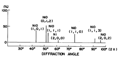
- the accompanying drawing shows an X-ray diffraction pattern of an electrode coating comprising a nickel oxide, a titanium component and a zirconium component, wherein the contents of the titanium component and the zirconium component in the coating are 1.2 % in terms of atomic percentage of titanium and 1.1 % in terms of atomic percentage of zirconium, respectively.
- a hydrogen-evolution electrode comprising an electrically conductive substrate having thereon a coating comprising a titanium component and a zirconium component dispersed in a base which is an oxide of nickel and/or cobalt, the titanium component and zirconium component being present in proportions of 0.1 to 3.5 % in terms of atomic percentage of titanium and 0.1 to 3 % in terms of atomic percentage of zirconium, respectively.
- the atomic percentage of titanium is defined by the formula: A Ti A T x 100 (%) wherein A Ti represents the number of titanium atoms in the coating and A T represents the total number of atoms of titanium, zirconium and nickel and/or cobalt in the coating; and the atomic percentage of zirconium is defined by the formula: A Zr A T x 100 (%) wherein A Zr represents the number of zirconium atoms in the coating and A T is as defined above.
- the coating of the electrode according to the present invention comprises an oxide of at least one of nickel and cobalt, a titanium component and a zirconium component.
- the oxide of nickel and/or cobalt in the coating enables the electrode to have a high catalytic activity, that is, enables the electrode to exhibit a low hydrogen overvoltage.
- the titanium component in the coating of the electrode imparts a reduction resistance to the oxide contained as an active material in the coating.
- reduction resistance used herein is intended to define such a property that the oxide as an active material in the electrode coating is not reduced and remains as an oxide even after the continuous operation of the electrolysis involving a hydrogen-evolution reaction.
- the zirconium component in the coating of the electrode not only prevents a lowering of the mechanical strength of the coating, which lowering is caused by repeated passages of an inverse current generated at the time of the halt of the electrolysis, but also suppresses the dissolution of the titanium component, which imparts a reduction resistance to the oxide as mentioned above, into an aqueous alkali solution. It has not yet been elucidated in what manner the zirconium component exerts such an effect. However, it is due to the effect exerted by the zirconium component that the electrode according to the present invention is free from the lowering of the mechanical strength of the coating and has a life markedly longer than that of the conventional electrodes.
- the coating of an electrode contains a titanium component in a proportion, in terms of atomic percentage of titanium, of from 0.1 to 3.5 %.
- the content of the titanium component in the coating is at least 0.1 %, preferably at least 0.2 %, more preferably at least 0.5 %, in terms of atomic percentage of titanium.
- an electrode having a coating containing a titanium component in a proportion of more than 3.5 % is disadvantageous because the electrode suffers from a lowering of the mechanical strength of the coating because the adhesion is poor between the substrate and the coating of the electrode.
- the coating of an electrode contains a zirconium component in a proportion, in terms of atomic percentage of zirconium, of from 0.1 to 3 %.
- the electrode suffers from a lowering of the mechanical strength of the coating and also suffers from a dissolution of the titanium component into the electrolyte.
- the content of the zirconium component in the coating is larger than 3 %, in terms of atomic percentage of zirconium, the electrode exhibits a disadvantageously high hydrogen overvoltage.
- titanium content means a percentage of the number of titanium atoms in the coating relative to the total number of atoms of titanium, zirconium and at least one metal selected from nickel and cobalt in the coating.
- the content of the titanium component is determined by first mixing an aliquot of the coating with a flux, next melting the resultant mixture, subsequently adding hot water and aqueous sulfuric acid thereto, and then subjecting the thus obtained homogeneous solution to atomic absorption analysis or plasma emission spectrophotometry, as described later.
- zirconium content means a percentage of the number of zirconium atoms in the coating relative to the total number of atoms of titanium, zirconium and at least one metal selected from nickel and cobalt in the coating.
- the content of the zirconium component is determined according to substantially the same procedure as mentioned above with respect to the determination of the content of the titanium component.
- An oxide of at least one metal selected from the group consisting of nickel and cobalt contained in the coating of the present invention may be nickel oxide, cobalt oxide and a mixture thereof, or a compound oxide containing nickel or cobalt.
- nickel oxide is most preferred.
- Cobalt oxide is suitable for the purpose of the present invention.
- detailed comparison between nickel oxide and cobalt oxide shows that nickel oxide is excellent in activity as compared to cobalt oxide.
- the titanium component may be titanium metal per se or an oxide thereof.
- the zirconium component may be zirconium metal per se or an oxide thereof.
- the titanium and zirconium components may also be in a state of a solid solution with an oxide of at least one metal selected from the group consisting of nickel and cobalt, or may be in an amorphous state so as to assume a mixture thereof with the oxide of at least one metal selected from nickel and cobalt.
- the titanium and zirconium components may be in the state of a compound oxide with at least one metal selected from the group consisting of nickel and cobalt.
- each of the zirconium and titanium components be in a state of a solid solution with an oxide of nickel or cobalt or be in an amorphous state so as to assume a mixture thereof with the oxide of nickel or cobalt. Presence of the solid solution in the coating can be confirmed by studying the X-ray diffraction pattern of the coating.
- the peak attributed to the solid solution of NiO with titanium and zirconium is observed, on the X-ray diffraction pattern of the coating, in a position slightly deviated from that of the peak attributed to the pure form of NiO.
- whether the zirconium and titanium components are in an amorphous state can be examined by studying the X-ray diffraction pattern of the coating. That is, when they are in an amorphous state, the peaks attributed to zirconium and titanium are not observed.
- the degree of oxidation of the coating of the electrode be in the range of from 20 to 99.5 %.
- the degree of oxidation of the coating is less than 20 %, the coating is likely to suffer from a lowering of the activity within a short period of time.
- the degree of oxidation of the coating is more than 99.5 %, the electrical conductivity is poor due to the increased electrical resistance, and also, the catalytic activity of the coating is likely to be low, so that the hydrogen overvoltage is likely to be high.
- degree of oxidation is defined as a value (%) calculated by the formula: H1 H1 + H0 x 100 wherein H0 represents the height of the highest intensity X-ray diffraction peak of a metal when the X-ray diffraction pattern exhibits X-ray diffraction peaks ascribed to a single species of metal and exhibits none of X-ray diffraction peaks ascribed to other species of metals, or represents the sum of the heights of the highest intensity X-ray diffraction peaks of individual metals when the X-ray diffraction pattern exhibits X-ray diffraction peaks ascribed to a plurality of species of metals; and H1 represents the height of the highest intensity X-ray diffraction peak of a metal oxide when the X-ray diffraction pattern exhibits X-ray diffraction peaks ascribed to a single species of metal oxide and exhibits none of X-ray diffraction peaks a
- suitable salts of nickel and/or cobalt, zirconium and titanium are, for example, nitrates, chlorides, formates, acetates and oxalates.
- suitable forms of nickel and/or cobalt, titanium and zirconium components include, for example, oxides, hydroxides, carbonates, formates, oxalates and metals per se. Of these, oxides of these metals are most preferred.
- suitable salts of nickel and/or cobalt, titanium and zirconium are, for example, sulfates, chlorides, nitrates, acetates and trichloroacetates.
- the method (2) comprising melt-spraying is most preferred from the viewpoints of the formation of a coating with a predetermined composition and the formation of an electrode having high activity which can be utilized for a prolonged period of time.
- the operations of melting of the powder and solidification and coating formation of the melted material on the substrate can be accomplished instantaneously, causing formation of a non-stoichiometric composition.
- non-stoichiometric composition an explanation is given below.
- oxidation of for example, nickel and titanium proceeds as follows: Ni2+ + O2 ⁇ ⁇ NiO, and Ti4+ + O2 ⁇ ⁇ TiO2.
- oxidation of nickel and titanium proceeds as follows: Ni2+ + O2 ⁇ ⁇ Ni 1-x O, and Ti4+ + O2 ⁇ ⁇ TiO 2-y wherein each of x and y independently represents a factor which produces non-stoichiometry.
- This formation of a non-stoichiometric composition is believed to contribute to the enhanced activity of an electrode coating obtained by melt-spraying.
- a uniform composition of a plurality of components can be easily obtained by mixing the components and granulating the mixture. Formulating such a uniform composition by melt-spray mixing, a desired electrode coating can be obtained. Therefore, the melt-spraying method is one of the most suitable methods for obtaining a hydrogen-evolution electrode having a coating of a plurality of specific components thereon, which coating is effective for attaining a high activity and long life.
- the starting materials for forming an oxide of at least one metal selected from the group consisting of nickel and cobalt and the starting materials for forming titanium and zirconium components be sufficiently mixed, milled and processed into granules before being subjected to melt-spraying.
- granulation techniques may be employed. They may be classified into several categories according to the type of apparatus, the state of the starting material, the granule-forming mechanism or the like.
- the granulation of powder may be carried out by means of a rotary drum-type apparatus or rotary dish-type apparatus in which a mixture of powder and liquid is processed into granules due to capillary absorption action or chemical reaction.
- the granulation may also be carried out by means of a spraying and drying-type apparatus in which raw materials in the form of a solution or suspension are formed into granules due to surface tension, drying and crystallization.
- the granulation may be carried out by means of a spraying and air cooling-type apparatus or spraying and water cooling-type apparatus in which a molten material is formed into granules due to surface tension, cooling and crystallization.
- a spraying and air cooling-type apparatus or spraying and water cooling-type apparatus in which a molten material is formed into granules due to surface tension, cooling and crystallization.
- Any of the above-mentioned granulation techniques can provide substantially spherical granules.
- the granulation by means of a spraying and drying-type apparatus is most preferred because it is advantageous in that uniformly porous granules are obtained so that the application of an active coating is facilitated and that well-bonded granules can be obtained, the size of the granules can be easily controlled, and granulation can be performed at low cost.
- a homogeneous suspension or solution is first prepared from starting material powders, a binding agent and water. Secondly, the suspension or solution is sprayed through a rotary disc, a two-channel nozzle, a pressure nozzle or the like to form liquid particles. Thirdly, the liquid particles are dried, thereby obtaining granules having a uniform composition, a uniform shape and a uniform size in which the components are bonded with a uniform bonding strength.
- a suitable binding agent to be employed for preparing granules there can be mentioned water-soluble high molecular weight organic substances, such as polyvinyl alcohol, polyvinyl acetate, gum arabic, carboxymethyl cellulose, methyl cellulose, ethyl cellulose and the like.
- These high molecular weight organic substances serve as the binding agent for component powdery materials in the granule-forming step, thereby to provide granules wherein the components are bonded with desired bonding strength.
- these organic substances almost completely disappear due to combustion or decomposition so that these substances exert no adverse effect on the resultant coating on the electrode.
- a dispersant for the purpose of obtaining uniform granules, there may be added a dispersant, antiflocculating agent, surfactant, antiseptic and the like.
- dispersants include a sodium salt of carboxymethyl cellulose having a molecular weight of 200 x 103 or more, methyl cellulose having a molecular weight or 140 x 103 or more, polyethylene glycol having a molecular weight of 120 x 103 or more and the like.
- antiflocculating agents include sodium hexametaphosphate, ammonium citrate, ammonium oxalate, ammonium tartrate, monoethylamine and the like.
- surfactants include alkyl aryl phosphates, alkyl aryl sulfonate, fatty acid soap and the like.
- antiseptics include sodium phenoxide, phenol, phenol derivatives, formaldehyde and the like. Generally, it is preferred that the powder material concentration of the suspension or solution be in the range of from 30 to 90 % by weight.
- the size of the granules prepared by the granulation technique by means of a spraying and drying-type apparatus may be in the range of preferably from 1 to 200 ⁇ m, more preferably from 5 to 100 ⁇ m.
- the granule size is too small, especially less than 1 ⁇ m, a large volume of dust occurs during the melt-spraying stage. This markedly lowers the melt-spraying yield, thereby causing performance of melt-spraying on a commercial scale to be difficult.
- the granules have a crushing strength of 0.5 g/granule or more. Such a level of crushing strength is needed to maintain their morphology during the storage and transportation after the granule formation.
- the crushing strength of the granules can be varied by changing the amount and/or kind of the binding agent to be employed.
- melt-spraying the granules there may be mentioned, for example, flame spraying and plasma spraying. Of the above-mentioned techniques, plasma spraying is more preferred.
- At least one type of gas selected from argon, nitrogen, hydrogen, helium and other gases is passed through a direct-current arc slit to thereby cause dissociation and ionization of the gas.
- This enables production of a plasma flame having a temperature as high as several thousand to more than ten thousand degrees centigrade and having a desired heat capacity and a high speed.
- the granules may be conveyed by an inert gas and poured in the plasma flame. The granules poured in the plasma flame is caused to melt fly and collide against the surface of the electrode substrate.
- the molten material on the electrode substrate may be cooled and solidified, to thereby form a coating on the substrate.
- the above-mentioned melting, flight and collision of the material can be accomplished instantaneously, for example, generally in a period of from 0.1 to 10 milliseconds.
- the temperature, heat capacity and speed of the plasma flame primarily depend on the type of gas employed and on the power of the arc.
- the suitable gas to be employed for producing the plasma flame there may be mentioned mixtures of gases, such as argon and nitrogen, argon and hydrogen, and nitrogen and hydrogen.
- the power of the arc depends on the arc current and arc voltage.
- the arc voltage at a fixed value of arc current, depends on the inter-electrode distance and the type and flow rate of plasma gas.
- a gas requiring a high energy for dissociation and ionization of molecules such as nitrogen
- the arc voltage is likely to increase.
- a gas which consists of single-atom molecules and which can be readily ionized such as argon
- the arc voltage is likely to decrease.
- there is no particular restriction in connection with the power of the arc as long as a plasma flame can be provided having a temperature and heat capacity sufficient to accomplish the above-mentioned melting of the granules instantaneously.
- the distance from the spray nozzle to the substrate to be spray coated and the angle at which the spray nozzle is disposed with respect to the face of the substrate to be spray coated there may be mentioned the distance from the spray nozzle to the substrate to be spray coated and the angle at which the spray nozzle is disposed with respect to the face of the substrate to be spray coated.
- the distance from the spray nozzle to the substrate to be coated is preferably 50 to 300 mm, and the angle at which the spray nozzle is disposed with respect to the substrate to be coated is preferably 30 to 150°.
- the method for pouring the granules in the plasma flame and the method for cooling the melt-sprayed material may affect the melt-spraying.
- these conditions are not of a critical nature and may be chosen from the conditions customarily employed.
- an additional component selected from zinc, zinc oxide, aluminum, silicon dioxide, molybdenum, molybdenum oxide and other substances may be incorporated in the granules. Incorporation of such an additional component is advantageous since it further improves the activity of the resultant electrode and further decreases the hydrogen overvoltage.
- the preferred thickness of the coating of electrode is 10 to 300 ⁇ m.
- the thickness of the coating is less than 10 ⁇ m, there cannot be obtained an electrode exhibiting a satisfactorily lowered hydrogen overvoltage.
- a thickness of the coating which exceeds 300 ⁇ m is not advantageous from an economical viewpoint because even if the coating thickness is more than 300 ⁇ m, the hydrogen overvoltage is not lowered beyond a certain value.
- the electrically conductive substrate of electrode should be sufficiently resistant to an electrolytic solution not only at a potential of the substrate during the electrolysis but also at a potential of the substrate at the time when the electrolysis is not effected.
- the surface of a substrate having an active, porous coating thereon has a potential which is noble as compared with the potential on the surface of the coating even during a period of time in which hydrogen is evolved from the surface of the coating of the electrode. Therefore, it is not unusual that the potential at the surface of the substrate is noble as compared with the dissolution-deposition equilibrium potential of iron.
- Examples of materials, which have an anticorrosive property sufficient for use as the substrate of the electrode of the present invention and are commercially available, include nickel, a nickel alloy, an austenite type stainless steel, a ferrite type stainless steel and the like. Of the above-mentioned materials, nickel, a nickel alloy and an austenite type stainless steel are preferred, and nickel and a nickel alloy are especially preferred. Besides, those which are each composed of an electrically conductive substrate having on its surface a non-pinhole coating of nickel, a nickel alloy or an austenite type stainless steel may also preferably be used as the substrate of electrode.
- Such a non-pinhole and anticorrosive coating may be obtained by known techniques, for example, electroplating, chemical plating, melt-plating, rolling, pressure-adhesion by explosion, cladding, vapor deposition, ionization plating and the like.
- the substrate of the electrode have a shape such that hydrogen gas generated during the electrolysis can be smoothly released so that a superfluous voltage loss due to the current-shielding by the hydrogen gas may be avoided and such that the effective surface area for electrolysis is large so that the current is hardly concentrated.
- the substrate having such a shape can be prepared from a wire screen having a suitable wire diameter and spacings between the respective adjacent wires, a perforated metal plate having a suitable thickness, size of openings and pitch of opening arrangement, an expanded metal having suitable lengths of long axis and short axis, or the like.
- the electrode of the present invention can be effectively used as a hydrogen-evolution electrode in various electrolyses, such as electrolysis of sodium chloride by the ion exchange membrane process or the diaphragm process, electrolysis of alkali metal halides other than sodium chloride, electrolysis of water and electrolysis of Glauber's salt. It is preferred that an electrolytic solution to be in contact with the electrode of the present invention be alkaline.
- the type of an electrolytic cell to be used together with the electrode of this invention may be of either monopolar arrangement or bipolar arrangement. When the electrode of the present invention is used in the electrolysis of water, it may be used as a bipolar electrode.
- the coatings of conventional hydrogen-evolution electrodes are likely to suffer from a lowering of mechanical strength which is caused by repeated passages of an inverse current under severe electrolytic conditions, such as a high temperature and a high alkali concentration.
- the lowering of mechanical strength in turn causes a coming-off of portions of the coating from the electrode, which is determined by measuring a weight decrease of the coating.
- the coming-off of portions of the coating adversely affects the activity of the coating, thereby leading to a disadvantageous increase in hydrogen overvoltage.
- the conversion of an oxide of nickel and/or cobalt to a hydroxide compound is brought about by repeated passages of an inverse current, which hydroxide compound disadvantageously increases hydrogen overvoltage.
- the hydrogen-evolution electrode of the present invention the lowering of mechanical strength and the adverse effect of the hydroxide compound, both of which are caused by the inverse current flowing at the time of temporarily halting the electrolytic operation, can be effectively suppressed by the incorporation of specific amounts of titanium and zirconium components. Therefore, the electrode of the present invention can be stably used while maintaining high activity for a prolonged period of time.
- the atomic percentages of a titanium and a zirconium in the coating of an electrode are determined by the ICAP (inductively coupled argon plasma emission spectrophotometer) method as follows.
- One part by weight of the coating of an electrode is mixed with 50 parts by weight of a flux (a mixture of 2 parts by weight of sodium peroxide and one part by weight of sodium carbonate) and the resultant mixture is calcined at a temperature of 600 °C or more.
- a flux a mixture of 2 parts by weight of sodium peroxide and one part by weight of sodium carbonate
- a predetermined amount of hot water and aqueous 50 % sulfuric acid are added to the resultant mixture to obtain a homogeneous solution.
- the obtained solution is used as the sample.
- the experimental conditions and apparatus used are as follows.
- Granules having a diameter of 30-44 ⁇ m are classified by means of a sieve.
- the minimum load (g) to crush a granule is determined with respect to 30 granules.
- the obtained values of load (g) are averaged.
- a mixture consisting of 100 parts by weight of powdery nickel oxide (NiO), 1.1 parts by weight of powdery titanium oxide (TiO2) and 1.8 parts by weight of powdery zirconium oxide (ZrO2) is added to an aqueous solution consisting of 100 parts by weight of water, 2.25 parts by weight of gum arabic as a binder, 0.7 part by weight of carboxymethyl cellulose as a dispersant, 0.001 part by weight of sodium lauryl sulfate as a surfactant and 0.1 part by weight of phenol as an antisepic agent.
- the resultant mixture is vigorously stirred to obtain a homogeneous suspension.
- the particle diameters of the nickel oxide, the titanium oxide and the zirconium oxide are measured as follows.
- the powdery nickel oxide is mixed with distilled water and a dispersant, and after sufficient stirring, the mixture is sprayed onto a copper mesh by means of a nebulizer, and dried. An electron photomicrograph is taken of the resultant nickel oxide powder.
- the particle diameter of the nickel oxide is in the range of from 0.2 to 2 ⁇ m
- the particle diameter of the titanium oxide is in the range of from 1 to 10 ⁇ m
- the particle diameter of the zirconium oxide is in the range of 0.1 to 1 ⁇ m.
- the suspension is dried and granulated by means of a spraying and drying type granulation chamber (hereinafter often referred to simply as "granulation chamber") having a diameter of 1 m and a height of 0.7 m and equipped at its top with a rotating disc.
- granulation chamber a spraying and drying type granulation chamber
- the suspension is fed to the granulation chamber at the rotating disc being rotated at 25,000 r.p.m. at a feed rate of 40 kg/hr by means of a pump, whereby the suspension becomes droplets and is dispersed while being subjected to gravity-dropping toward the bottom of the granulation chamber.
- a hot air of 330 °C is fed to the granulation chamber so that the hot air flows in the same direction as the dispersed droplets fall.
- the flow rate of the hot air is adjusted so that the hot-air temperature is 120 °C at the outlet of the hot air located at the side portion of the bottom of the granulation chamber.
- Spherical granules having temperatures of 95 to 100 °C are produced at a production rate of about 18 kg/hr.
- the produced granules are taken out from the bottom of the granulation chamber and allowed to stand for cooling.
- the obtained granules are 5 to 50 ⁇ m in diameter as determined by the electron microscopic method, 5 g/granule in crushing strength and less than 0.1 % in water content.
- a 5 cm x 5 cm nickel wire screen (wire diameter, 0.7 mm; 14 mesh) is degreased with trichlene, and then both sides thereof are blasted by means of Al2O3 having a particle size of 0.73 to 2.12 mm.
- the blasted wire screen (substrate) is melt spray coated on both sides thereof with the above-prepared granules by plasma spraying as indicated below.
- the plasma spraying is repeated 3 times with respect to each side of the wire screen to produce an electrode having a coating of a thickness of 150 ⁇ m with respect to one side of the wire screen and 100 ⁇ m with respect to the other side of the wire screen.
- Plasma spraying is done using the following average spraying parameters. Feeding rate of plasma gas of nitrogen and hydrogen: 2 m3 (at normal state)/hr and 0.4 m3 (at normal stated/hr, respectively.
- composition of the coating of the electrode and the degree of oxidation of the coating are determined as follows.
- the titanium component content and the zirconium component content are 1.2 % in terms of atomic percentage of titanium and 1.1 % in terms of atomic percentage of zirconium, respectively.
- the coating is subjected to X-ray diffractometry to determine the crystal structure of the coating.
- the obtained X-ray diffraction pattern is shown in FIGURE.
- the peaks attributed to NiO and Ni are observed, from which the degree of oxidation is calculated to be 62 %.
- the X-ray diffraction pattern there is no peak attributed to titanium oxide, titanium metal, zirconium oxide, zirconium metal, a compound oxide of nickel and titanium and a compound oxide of nickel and zirconium (see FIGURE).
- the lattice constant of NiO is calculated from the position of the peak of NiO.
- the lattice constant is found to be 4.175 ⁇ .
- the lattice constant of NiO of a further electrode which has been prepared in substantially the same manner as in Example 1 except that only powdery nickel oxide is used instead of the combination of powdery nickel oxide, powdery titanium oxide and powdery zirconium oxide, is 4.178 ⁇ . Therefore, it is believed that titanium and zirconium components are present together with the nickel oxide in the form of a solid solution or in an amorphous form.
- an electrolytic cell provided with a platinum wire electrode as an anode and introduction means for additionally introducing a 40 % by weight aqueous solution of sodium hydroxide during electrolysis.
- a 45 % aqueous solution of sodium hydroxide is initially contained.
- the above-obtained electrode is installed as a cathode in the electrolytic cell in such a manner that the side of the cathode on which a 150 ⁇ m-thick coating is formed faces the platinum wire anode.
- the electrolysis is conducted for 800 hours while compulsorily applying an inverse current of 0.3 A/dm2 once a day for one hour, and the hydrogen overvoltage, the degree of oxidation of the coating and the weight decrease of the coating are measured.
- the results are shown in Table 1.
- Electrodes are prepared in substantially the same manner as described in Example 1 except that the amounts of oxides are changed so as for the coating to contain titanium and zirconium in the amounts indicated in Table 2.
- the titanium content and the zirconium content are summarized for each electrode in Table 2.
- the degree of oxidation determined by X-ray diffractormetry ranges from 62 to 65 %. Electrolysis is carried out in the same manner and under the same conditions as described in Example 1, to thereby measure hydrogen overvoltage values and weight loss values of the coatings in the same manner as in Example 1. The results are shown in Table 2.
- Electrodes are prepared in substantially the same manner as described in Example 1, except that cobalt oxide is used instead of nickel oxide and the amounts of oxides are changed so as for the coating to contain titanium and zirconium in the amounts indicated in Table 2.
- the measurement by means of an electron microscope shows that the particle diameter of the cobalt oxide ranges from 0.4 to 2 ⁇ m.
- the titanium content and the zirconium content are summarized for each electrode in Table 2.
- the degree of oxidation determined by X-ray diffractormetry ranges from 68 to 74 %.
- Electrolysis is carried out in the same manner and under the same conditions as described in Example 1, to thereby measure hydrogen overvoltage values and weight loss values of the coatings in the same manner as in Example 1. The results are shown in Table 2.
- Electrodes are prepared in substantially the same manner as in Example 1, except that the types and atomic percentages of other than nickel oxide are changed as indicated in Table 2 and that as a plasma gas a mixed gas of argon and nitrogen is used instead of the mixed gas of nitrogen and hydrogen and the argon and nitrogen are flowed at rates of 1 m3(in normal state)/hr and 0.8 m3(in normal state)/hr, respectively.
- the chromium oxide used in Comparative Example 5 has a particle diameter of from 0.5 to 3 ⁇ m.
- the titanium content and the zirconium content are summarized for each electrode in Table 2. The degree of oxidation determined by X-ray diffractometry ranges from 85 to 87 %. Electrolysis is carried out in the same manner and under the same conditions as described in Example 1, to thereby measure hydrogen overvoltage values and weight loss values of the coatings in the same manner as in Example 1. The results are shown in Table 2.
Landscapes
- Chemical & Material Sciences (AREA)
- Engineering & Computer Science (AREA)
- Chemical Kinetics & Catalysis (AREA)
- Electrochemistry (AREA)
- Materials Engineering (AREA)
- Metallurgy (AREA)
- Organic Chemistry (AREA)
- Electrodes For Compound Or Non-Metal Manufacture (AREA)
Claims (4)
- Électrode de dégagement d'hydrogène comprenant un substrat conducteur de l'électricité sur lequel est appliqué un revêtement comprenant un constituant de titane et un constituant de zirconium dispersé dans une base, qui est un oxyde de nickel et/ou de cobalt, le constituant de titane et le constituant de zirconium étant présents en des proportions de 0,1 à 3,5 % en pourcentage atomique de titane et de 0,1 à 3 % en pourcentage atomique de zirconium respectivement,
le pourcentage atomique de titane étant défini par la formule
le pourcentage atomique du zirconium étant défini par la formule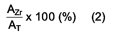
- Électrode suivant la revendication 1, dans laquelle le substrat conducteur d'électricité comprend une matière anticorrosive choisie parmi le nickel, un alliage de nickel et un acier inoxydable de type austénite.
- Électrode suivant la revendication 1 ou 2, dans laquelle le revêtement comprend un oxyde de nickel, du nickel, du titane ou du zirconium.
- Électrode suivant l'une des revendications 1 à 3, dans laquelle le revêtement a un degré d'oxydation de 20 à 99,5 %, le degré d'oxydation étant défini par la formule:

Applications Claiming Priority (2)
| Application Number | Priority Date | Filing Date | Title |
|---|---|---|---|
| JP211373/89 | 1989-08-18 | ||
| JP1211373A JPH0375392A (ja) | 1989-08-18 | 1989-08-18 | 水素発生用電極 |
Publications (2)
| Publication Number | Publication Date |
|---|---|
| EP0413480A1 EP0413480A1 (fr) | 1991-02-20 |
| EP0413480B1 true EP0413480B1 (fr) | 1994-02-02 |
Family
ID=16604888
Family Applications (1)
| Application Number | Title | Priority Date | Filing Date |
|---|---|---|---|
| EP90308567A Expired - Lifetime EP0413480B1 (fr) | 1989-08-18 | 1990-08-03 | Electrode pour le dégagement d'hydrogène présentant une haute durabilité et stabilité |
Country Status (5)
| Country | Link |
|---|---|
| US (1) | US5084154A (fr) |
| EP (1) | EP0413480B1 (fr) |
| JP (1) | JPH0375392A (fr) |
| CN (1) | CN1025443C (fr) |
| DE (1) | DE69006428T2 (fr) |
Families Citing this family (14)
| Publication number | Priority date | Publication date | Assignee | Title |
|---|---|---|---|---|
| EP0546714B1 (fr) * | 1991-12-13 | 1999-08-04 | Imperial Chemical Industries Plc | Cathode pour cellule d'électrolyse |
| US5670115A (en) * | 1995-10-16 | 1997-09-23 | General Motors Corporation | Hydrogen sensor |
| DE10007480A1 (de) * | 2000-02-18 | 2001-08-23 | Provera Ges Fuer Projektierung | Bipolare Elektrode mit Halbleiterbeschichtung und damit verbundenes Verfahren zur elektrolytischen Wasserspaltung |
| US20100193363A1 (en) * | 2009-01-30 | 2010-08-05 | Shrisudersan Jayaraman | Electrochemical methods of making nanostructures |
| US9211155B2 (en) * | 2008-08-20 | 2015-12-15 | Prostacare Pty Ltd. | Non-thermal ablation system for treating BPH and other growths |
| GB2469265B8 (en) * | 2009-04-06 | 2015-06-17 | Re Hydrogen Ltd | Electrode configuration of electrolysers to protect catalyst from oxidation |
| CN104591343B (zh) * | 2014-12-18 | 2016-08-17 | 北京师范大学 | 用于有机工业废水深度处理的多孔PbO2电极的制备方法 |
| DE102015120057A1 (de) * | 2015-11-19 | 2017-05-24 | Zentrum für Sonnenenergie- und Wasserstoff-Forschung Baden-Württemberg Gemeinnützige Stiftung | Nickelelektrode, freitragende Nickelschicht, Verfahren zu deren Herstellung und deren Verwendung |
| DE102017110863B4 (de) * | 2017-05-18 | 2021-02-04 | Zentrum für Sonnenenergie- und Wasserstoff-Forschung Baden-Württemberg | Nickelelektrode, Verfahren zu deren Herstellung und deren Verwendung |
| JP6834860B2 (ja) | 2017-09-05 | 2021-02-24 | トヨタ自動車株式会社 | 衝突防止装置、衝突防止方法、衝突防止プログラム、記録媒体 |
| KR102659146B1 (ko) | 2017-11-27 | 2024-04-22 | 프로스타캐어 피티와이 엘티디 | 전립선 질환의 치료를 위한 장치 및 방법 |
| US11224474B2 (en) | 2018-02-28 | 2022-01-18 | Prostacare Pty Ltd | System for managing high impedance changes in a non-thermal ablation system for BPH |
| WO2025223593A1 (fr) | 2024-04-25 | 2025-10-30 | BREITMAYER, Jürgen | Système de gaz de réacteur avec moteur et générateur |
| WO2025223592A1 (fr) | 2024-04-25 | 2025-10-30 | BREITMAYER, Jürgen | Système de réacteur basé sur un système d'électrolyse alcaline pour la production d'un gaz combustible et processus de production du gaz combustible au moyen du réacteur |
Family Cites Families (7)
| Publication number | Priority date | Publication date | Assignee | Title |
|---|---|---|---|---|
| US3977958A (en) * | 1973-12-17 | 1976-08-31 | The Dow Chemical Company | Insoluble electrode for electrolysis |
| US3992278A (en) * | 1975-09-15 | 1976-11-16 | Diamond Shamrock Corporation | Electrolysis cathodes having a melt-sprayed cobalt/zirconium dioxide coating |
| FR2423065A1 (fr) * | 1978-04-12 | 1979-11-09 | Battelle Memorial Institute | Procede de fabrication d'electrodes pour piles a combustible, dispositif pour la mise en oeuvre du procede et electrodes resultant de ce procede |
| EP0031948B1 (fr) * | 1979-12-26 | 1986-10-15 | Asahi Kasei Kogyo Kabushiki Kaisha | Electrode pour l'évolution d'hydrogène |
| FI73246C (fi) * | 1982-11-30 | 1987-09-10 | Asahi Chemical Ind | Vaetealstrande elektrod och foerfarande foer dess framstaellning. |
| JPH0633483B2 (ja) * | 1983-07-22 | 1994-05-02 | 旭化成工業株式会社 | 水素発生用電極 |
| JPS6286187A (ja) * | 1985-10-09 | 1987-04-20 | Asahi Chem Ind Co Ltd | 水素発生用の電極 |
-
1989
- 1989-08-18 JP JP1211373A patent/JPH0375392A/ja active Pending
-
1990
- 1990-08-03 DE DE90308567T patent/DE69006428T2/de not_active Expired - Fee Related
- 1990-08-03 EP EP90308567A patent/EP0413480B1/fr not_active Expired - Lifetime
- 1990-08-06 US US07/563,059 patent/US5084154A/en not_active Expired - Fee Related
- 1990-08-18 CN CN90107148A patent/CN1025443C/zh not_active Expired - Fee Related
Also Published As
| Publication number | Publication date |
|---|---|
| CN1049534A (zh) | 1991-02-27 |
| US5084154A (en) | 1992-01-28 |
| JPH0375392A (ja) | 1991-03-29 |
| CN1025443C (zh) | 1994-07-13 |
| EP0413480A1 (fr) | 1991-02-20 |
| DE69006428D1 (de) | 1994-03-17 |
| DE69006428T2 (de) | 1994-05-11 |
Similar Documents
| Publication | Publication Date | Title |
|---|---|---|
| EP0413480B1 (fr) | Electrode pour le dégagement d'hydrogène présentant une haute durabilité et stabilité | |
| El Baydi et al. | A sol-gel route for the preparation of Co3O4 catalyst for oxygen electrocatalysis in alkaline medium | |
| US4605484A (en) | Hydrogen-evolution electrode | |
| US4402815A (en) | Electrodes containing nickel alloys as electrocatalysts | |
| US5261944A (en) | Nickel cermet, and process for preparing it | |
| US4555317A (en) | Cathode for the electrolytic production of hydrogen and its use | |
| KR20210040609A (ko) | 다공성 Ni-Fe-Al 촉매층이 형성된 알칼리 수전해용 양극 및 그 제조방법 | |
| CA1208600A (fr) | Procede de fabrication de cathodes par deposition a l'arc de nickel et d'aluminium avec lessivage de ce dernier | |
| US4839015A (en) | Hydrogen-evolution electrode and a method of producing the same | |
| US4696731A (en) | Amorphous metal-based composite oxygen anodes | |
| Schiller et al. | Vacuum plasma sprayed electrodes for advanced alkaline water electrolysis | |
| RU2045583C1 (ru) | Способ получения электрода | |
| EP1235658B1 (fr) | Electrode produite avec poudre catalytique | |
| US4746584A (en) | Novel amorphous metal alloys as electrodes for hydrogen formation and oxidation | |
| EP0226291B1 (fr) | Procédé pour accroître la longévité d'une électrode à évolution d'hydrogène | |
| JPH0633483B2 (ja) | 水素発生用電極 | |
| JPH05117889A (ja) | 酸素発生用のセラミツク陽極及びその製造方法と使用法 | |
| SU1658822A3 (ru) | Электрод дл получени водорода | |
| JPH0344154B2 (fr) | ||
| JPH03166393A (ja) | 水素発生用の電極 | |
| EP0209264A1 (fr) | Alliages métalliques amorphes à base de rhodium et leur utilisation comme électrodes dégageant du chlore | |
| Kötz | RuO2/IrO2 electrocatalysts for anodic O2 evolution | |
| JP2025040105A (ja) | 酸素還元型食塩電解の運転方法 |
Legal Events
| Date | Code | Title | Description |
|---|---|---|---|
| PUAI | Public reference made under article 153(3) epc to a published international application that has entered the european phase |
Free format text: ORIGINAL CODE: 0009012 |
|
| 17P | Request for examination filed |
Effective date: 19900823 |
|
| AK | Designated contracting states |
Kind code of ref document: A1 Designated state(s): BE DE FR GB IT |
|
| 17Q | First examination report despatched |
Effective date: 19930215 |
|
| GRAA | (expected) grant |
Free format text: ORIGINAL CODE: 0009210 |
|
| AK | Designated contracting states |
Kind code of ref document: B1 Designated state(s): BE DE FR GB IT |
|
| PGFP | Annual fee paid to national office [announced via postgrant information from national office to epo] |
Ref country code: FR Payment date: 19940204 Year of fee payment: 5 |
|
| ITF | It: translation for a ep patent filed | ||
| REF | Corresponds to: |
Ref document number: 69006428 Country of ref document: DE Date of ref document: 19940317 |
|
| PGFP | Annual fee paid to national office [announced via postgrant information from national office to epo] |
Ref country code: BE Payment date: 19940413 Year of fee payment: 5 |
|
| ET | Fr: translation filed | ||
| PGFP | Annual fee paid to national office [announced via postgrant information from national office to epo] |
Ref country code: GB Payment date: 19940624 Year of fee payment: 5 |
|
| PGFP | Annual fee paid to national office [announced via postgrant information from national office to epo] |
Ref country code: DE Payment date: 19941020 Year of fee payment: 5 |
|
| PLBE | No opposition filed within time limit |
Free format text: ORIGINAL CODE: 0009261 |
|
| STAA | Information on the status of an ep patent application or granted ep patent |
Free format text: STATUS: NO OPPOSITION FILED WITHIN TIME LIMIT |
|
| 26N | No opposition filed | ||
| PG25 | Lapsed in a contracting state [announced via postgrant information from national office to epo] |
Ref country code: GB Effective date: 19950803 |
|
| PG25 | Lapsed in a contracting state [announced via postgrant information from national office to epo] |
Ref country code: BE Effective date: 19950831 |
|
| BERE | Be: lapsed |
Owner name: ASAHI KASEI KOGYO K.K. Effective date: 19950831 |
|
| GBPC | Gb: european patent ceased through non-payment of renewal fee |
Effective date: 19950803 |
|
| PG25 | Lapsed in a contracting state [announced via postgrant information from national office to epo] |
Ref country code: FR Effective date: 19960430 |
|
| PG25 | Lapsed in a contracting state [announced via postgrant information from national office to epo] |
Ref country code: DE Effective date: 19960501 |
|
| REG | Reference to a national code |
Ref country code: FR Ref legal event code: ST |
|
| PG25 | Lapsed in a contracting state [announced via postgrant information from national office to epo] |
Ref country code: IT Free format text: LAPSE BECAUSE OF NON-PAYMENT OF DUE FEES;WARNING: LAPSES OF ITALIAN PATENTS WITH EFFECTIVE DATE BEFORE 2007 MAY HAVE OCCURRED AT ANY TIME BEFORE 2007. THE CORRECT EFFECTIVE DATE MAY BE DIFFERENT FROM THE ONE RECORDED. Effective date: 20050803 |