EP0413541A1 - Moteur à combustion interne À pistons rotatifs - Google Patents
Moteur à combustion interne À pistons rotatifs Download PDFInfo
- Publication number
- EP0413541A1 EP0413541A1 EP90308887A EP90308887A EP0413541A1 EP 0413541 A1 EP0413541 A1 EP 0413541A1 EP 90308887 A EP90308887 A EP 90308887A EP 90308887 A EP90308887 A EP 90308887A EP 0413541 A1 EP0413541 A1 EP 0413541A1
- Authority
- EP
- European Patent Office
- Prior art keywords
- rotor
- cylinder
- engine
- valve
- rotary
- Prior art date
- Legal status (The legal status is an assumption and is not a legal conclusion. Google has not performed a legal analysis and makes no representation as to the accuracy of the status listed.)
- Withdrawn
Links
- 238000002485 combustion reaction Methods 0.000 title claims abstract description 33
- 239000000567 combustion gas Substances 0.000 claims description 22
- 239000007789 gas Substances 0.000 claims description 21
- 238000007789 sealing Methods 0.000 claims description 8
- 238000010408 sweeping Methods 0.000 claims description 4
- 230000001360 synchronised effect Effects 0.000 claims description 3
- 230000002093 peripheral effect Effects 0.000 claims 1
- 230000006835 compression Effects 0.000 description 5
- 238000007906 compression Methods 0.000 description 5
- 238000010276 construction Methods 0.000 description 2
- 238000001816 cooling Methods 0.000 description 2
- 239000012530 fluid Substances 0.000 description 2
- 230000004048 modification Effects 0.000 description 2
- 238000012986 modification Methods 0.000 description 2
- 125000004122 cyclic group Chemical group 0.000 description 1
- 230000003247 decreasing effect Effects 0.000 description 1
- 229910003460 diamond Inorganic materials 0.000 description 1
- 239000010432 diamond Substances 0.000 description 1
- 239000002283 diesel fuel Substances 0.000 description 1
- 230000000694 effects Effects 0.000 description 1
- 239000000446 fuel Substances 0.000 description 1
- 239000008246 gaseous mixture Substances 0.000 description 1
- 230000005484 gravity Effects 0.000 description 1
- 239000007788 liquid Substances 0.000 description 1
- 238000005461 lubrication Methods 0.000 description 1
- 238000004519 manufacturing process Methods 0.000 description 1
- 239000000463 material Substances 0.000 description 1
- 238000005204 segregation Methods 0.000 description 1
Images

Classifications
-
- F—MECHANICAL ENGINEERING; LIGHTING; HEATING; WEAPONS; BLASTING
- F01—MACHINES OR ENGINES IN GENERAL; ENGINE PLANTS IN GENERAL; STEAM ENGINES
- F01C—ROTARY-PISTON OR OSCILLATING-PISTON MACHINES OR ENGINES
- F01C1/00—Rotary-piston machines or engines
- F01C1/08—Rotary-piston machines or engines of intermeshing engagement type, i.e. with engagement of co- operating members similar to that of toothed gearing
- F01C1/12—Rotary-piston machines or engines of intermeshing engagement type, i.e. with engagement of co- operating members similar to that of toothed gearing of other than internal-axis type
- F01C1/14—Rotary-piston machines or engines of intermeshing engagement type, i.e. with engagement of co- operating members similar to that of toothed gearing of other than internal-axis type with toothed rotary pistons
- F01C1/20—Rotary-piston machines or engines of intermeshing engagement type, i.e. with engagement of co- operating members similar to that of toothed gearing of other than internal-axis type with toothed rotary pistons with dissimilar tooth forms
Definitions
- This invention relates to a rotary internal combustion engine.
- a rotary internal combustion engine comprising a rotor mounted for rotation concentrically within a closed ended cylindrical bore formed within a cylinder block, the rotor being separated from the internal cylinder wall by an annular chamber spanned and swept by two rotor blades secured to, spaced about and extending along the side of the rotor and sealingly engagable with the inner periphery of the cylinder; a combustion gas inlet port and an exhaust gas outlet port to the annular chamber; a first rotary cylinder valve mounted in the cylinder block for rotation about an axis parallel to that of the rotor, connecting into and spacing across the annular chamber and disposed between the inlet and the outlet ports, and a second rotary cylinder valve mounted in the cylinder block for rotation about an axis parallel to that of the rotor connecting into and spanning across the annular chamber, both the first and the second cylinder valves being provided with elongate slots along their length adapted to receive and cooperate with the rot
- the second rotary cylinder valve may contain or connect to a reservoir chamber for the collection under increased pressure of combustion gas.
- a rotary internal combustion engine effectively free from epicyclic and reciprocating motion.
- the rotary valves enable power to be extracted from the engine by means of the bladed rotor.
- the construction enables the cylindrical valves to "roll" synchronously against the rotor, whilst allowing the rotor blades to pass by and maintain their cyclic path and at the same time provide a boundary for combustion and exhaust gases.
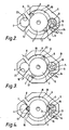
- the internal combustion engine comprises a main shaft 1 and a principle rotor 2 connected by means of gearing 3 to cylindrical valves 4 and 5.
- a pair of diametrically opposed rotor blades 6 and 7 are secured to and extend along the periphery of the rotor 2 such as to bear by means of sealing strips 12 and 13 against the cylindrical inner wall 19 of the cylinder block 9.
- the cylindrical inner wall 19 of the cylinder block and the concentric rotor 2 define between them an annular chamber 20 in association with end plates 22 and 35.
- the rotor blades 6 and 7 include outwardly extending sealing cheeks 25 and 26 on each side urged apart by spring means 28.
- Each sealing cheek is provided with a bottom edge 29 locatable under a rim on the respective blade to limit outward movement.
- the rotor blades are povided with keyways 30 for attachment to the rotor.
- the sealing strip 12 is located within an appropriate groove 31 in each rotor blade and is urged outwardly by spring means 32. The lateral movement is kept to a minimum whilst allowing for wear and play tolerances.
- the spring forces being sufficient to contain pressures of combustion.
- a combustion gas inlet port 8 and an exhaust gas outlet port 16 connect to the annular chamber 20.
- a spark ignition plug 14 is connected into a combustion chamber portion 15 of the annular chamber 20.
- the second rotary valve 5 is provided with a passage 10 leading to a reservoir for compressed combustion gas 11.
- Figure 2 shows the engine with the combustion chamber 15 formed between valve 5 and blade 7 ready for ignition with compressed combustion gas therein.
- Figure 3 shows the arrangement after ignition of the combustion gas, with the rotor blade 7 being swept towards the exhaust port 16 and the cylindrical valve 4, at the same time sweeping out combustion gas through outlet port 16 from a previous combustion ahead of rotor blade 7. At the same time combustion gas is sweeping into the annular chamber via inlet port 8 behind rotor blade 6 which is also compressing and feeding ahead of itself further combustion gas towards rotary valve 5.
- Figure 4 shows the engine with the rotor blades 6 and 7 engaging in the appropriately shaped partly cylindrical slots or grooves 23, 24 in cylindrical valves 4 and 5. At this position exhaust gases can leave via outlet port 16, whilst combustion gases compressed ahead of rotor blade 6 are forced via passage 10 into reservoir 11.
- the rotating cylinder valve 5 turns such that the passage 10 is opened to the reservoir chamber 11 therein.
- the cylinder valve curve surfaces synchronously mate with the rotor maintaining a boundary to the gases, whilst the rotor blades, by means of sealing edges 12, 13 ensure sealing with the cylinder block 9, and as the rotor blades pass by the cylindrical valves maintain an orbital path with respect to the main shaft and rotor.
- the sealing cheeks 25 and 26 of each rotor blade engage and co-operate within the cylindrical valves 4 and 5 as the rotor blades pass therethrough, thereby assisting gas transfer efficiency.
- the number of cylinder valves and rotor blades may be, in some embodiments of the invention, greater than those described hereinabove.
- passages for gas tranference may also be varied to suit alternative arrangements for compression and combustion chamber segregation.
- Cooling means may be incorporated throughout the block constituting the combustion chamber by means of channels 17 via which fluid may be passed, utilising the power from the engine to achieve the fluid flow.
- the reservoir 11 may be part of the cylindrical valve 5 as shown or externally thereto, the volume effecting the peak compression pressure an initial period to operational pressure levels.
- Lubrication of relevant surfaces may be provided using appropriate channels 18 and 27 through which cooling may also be effected and surface contact areas reduced for the rotor and cylinder valves to reduce friction losses.
- Diesel fuels may be used with the use of injectors to achieve the high compression required along with rechannelled gas paths to enable high performance.
- the engine may be modified from that illustrated in that pressurised gas or liquid may be utilised to extract power.
- the engine herein described differs from and is a significant improvement over the forementioned commercially developed "rotary" engine in that the output shaft may be fixed to the rotor directly thereby removing the need for heavily loaded precision gears, although simple gearing means are, as illustrated, used for synchronisation of the cylindrical valves with the principal rotor.
- the rotor additionally is fixed to the centre of the cylinder block, with the centre of gravity thereof lying on the centre line of the output shaft to provide a freedom from eccentric movement thereby, and hence reduction in vibration.
- the rotor blades travel concentric to the main output shaft, and the cylindrical valves are used to allow the blades to rotate freely whilst allowing either of the gas to pass in front of the blade or behind it, gas transfer being accomplished either side of one of the cylindrical valves.
- the overall annular chamber including the combustion chamber (formed by the main cylinder block) is of a compact configuration of primarily diamond configuration and of similar dimensions in length as to its width and depth. However of course the shape can be varied to achieve differently dimensioned combustion chambers for optimisation of effeciency.
Landscapes
- Engineering & Computer Science (AREA)
- Mechanical Engineering (AREA)
- General Engineering & Computer Science (AREA)
- Combustion Methods Of Internal-Combustion Engines (AREA)
Applications Claiming Priority (2)
| Application Number | Priority Date | Filing Date | Title |
|---|---|---|---|
| GB8918932 | 1989-08-18 | ||
| GB898918932A GB8918932D0 (en) | 1989-08-18 | 1989-08-18 | Rotary internal combustion engine |
Publications (1)
| Publication Number | Publication Date |
|---|---|
| EP0413541A1 true EP0413541A1 (fr) | 1991-02-20 |
Family
ID=10661859
Family Applications (1)
| Application Number | Title | Priority Date | Filing Date |
|---|---|---|---|
| EP90308887A Withdrawn EP0413541A1 (fr) | 1989-08-18 | 1990-08-13 | Moteur à combustion interne À pistons rotatifs |
Country Status (2)
| Country | Link |
|---|---|
| EP (1) | EP0413541A1 (fr) |
| GB (1) | GB8918932D0 (fr) |
Cited By (2)
| Publication number | Priority date | Publication date | Assignee | Title |
|---|---|---|---|---|
| WO2008108743A1 (fr) * | 2007-03-02 | 2008-09-12 | Peter Varga | Moteur rotatif à combustion interne avec chambre annulaire |
| WO2008121082A1 (fr) * | 2007-04-03 | 2008-10-09 | Peter Varga | Moteur à combustion interne rotatif avec chambre annulaire |
Citations (7)
| Publication number | Priority date | Publication date | Assignee | Title |
|---|---|---|---|---|
| GB784554A (en) * | 1955-08-30 | 1957-10-09 | Clifford Edmund Brewer | Improvements in or relating to rotary motors, compressors or the like |
| US3453992A (en) * | 1968-07-08 | 1969-07-08 | Anthony Graham | Rotary type device |
| FR1594801A (fr) * | 1968-11-20 | 1970-06-08 | ||
| FR2113141A5 (fr) * | 1970-10-22 | 1972-06-23 | Przybylski Zdzislaw | |
| US3863610A (en) * | 1972-08-18 | 1975-02-04 | Raymond G Spinnett | Rotary converters having specialized interleaving elements |
| FR2243607A5 (en) * | 1973-09-10 | 1975-04-04 | Widemann Antoine | Rotary I.C. engine with gear type rotors - blades of central rotor engage recesses on adjacent rotors |
| DE3543944A1 (de) * | 1985-12-12 | 1987-06-19 | Werner Gleixner | Brennkraftmaschine |
-
1989
- 1989-08-18 GB GB898918932A patent/GB8918932D0/en active Pending
-
1990
- 1990-08-13 EP EP90308887A patent/EP0413541A1/fr not_active Withdrawn
Patent Citations (7)
| Publication number | Priority date | Publication date | Assignee | Title |
|---|---|---|---|---|
| GB784554A (en) * | 1955-08-30 | 1957-10-09 | Clifford Edmund Brewer | Improvements in or relating to rotary motors, compressors or the like |
| US3453992A (en) * | 1968-07-08 | 1969-07-08 | Anthony Graham | Rotary type device |
| FR1594801A (fr) * | 1968-11-20 | 1970-06-08 | ||
| FR2113141A5 (fr) * | 1970-10-22 | 1972-06-23 | Przybylski Zdzislaw | |
| US3863610A (en) * | 1972-08-18 | 1975-02-04 | Raymond G Spinnett | Rotary converters having specialized interleaving elements |
| FR2243607A5 (en) * | 1973-09-10 | 1975-04-04 | Widemann Antoine | Rotary I.C. engine with gear type rotors - blades of central rotor engage recesses on adjacent rotors |
| DE3543944A1 (de) * | 1985-12-12 | 1987-06-19 | Werner Gleixner | Brennkraftmaschine |
Cited By (2)
| Publication number | Priority date | Publication date | Assignee | Title |
|---|---|---|---|---|
| WO2008108743A1 (fr) * | 2007-03-02 | 2008-09-12 | Peter Varga | Moteur rotatif à combustion interne avec chambre annulaire |
| WO2008121082A1 (fr) * | 2007-04-03 | 2008-10-09 | Peter Varga | Moteur à combustion interne rotatif avec chambre annulaire |
Also Published As
| Publication number | Publication date |
|---|---|
| GB8918932D0 (en) | 1989-09-27 |
Similar Documents
| Publication | Publication Date | Title |
|---|---|---|
| US5494014A (en) | Rotary internal combustion engine | |
| US3855977A (en) | Rotary internal-combustion engine | |
| US7621255B2 (en) | Toroidal engine method and apparatus | |
| EP0890721A1 (fr) | Machine motrice rotative a aubes | |
| CN1022772C (zh) | 组合式叶片旋转发动机 | |
| US6401686B1 (en) | Apparatus using oscillating rotating pistons | |
| EP0510125B1 (fr) | Moteur a combustion interne rotatif | |
| US3931809A (en) | Rotary internal combustion engine | |
| US6945217B2 (en) | Rotary machine | |
| US6526937B1 (en) | Economical eccentric internal combustion engine | |
| US4864814A (en) | Continuous combustion heat engine | |
| US8616176B2 (en) | Rotary internal combustion engine | |
| US6298821B1 (en) | Bolonkin rotary engine | |
| JPH0674721B2 (ja) | 一体構造のピストンとシリンダ−壁部分を有する機械 | |
| EP0734486B1 (fr) | Moteur rotatif | |
| US4007715A (en) | Rotary engines, compressors and vacuum pumps | |
| KR100678485B1 (ko) | 회전식 내연기관 | |
| US5433176A (en) | Rotary-reciprocal combustion engine | |
| US3934559A (en) | Anti-pollutant spherical rotary engine with automatic supercharger | |
| JPH1068301A (ja) | ベーン回転式容積変化装置及びそれを用いた内燃機関 | |
| US7621254B2 (en) | Internal combustion engine with toroidal cylinders | |
| US7398757B2 (en) | Toroidal engine method and apparatus | |
| US5131359A (en) | Rotating head and piston engine | |
| WO1991005940A1 (fr) | Pompe ou moteur | |
| EP0915238A2 (fr) | Moteur a combustion interne avec distribution des gaz par fentes |
Legal Events
| Date | Code | Title | Description |
|---|---|---|---|
| PUAI | Public reference made under article 153(3) epc to a published international application that has entered the european phase |
Free format text: ORIGINAL CODE: 0009012 |
|
| AK | Designated contracting states |
Kind code of ref document: A1 Designated state(s): DE FR GB |
|
| STAA | Information on the status of an ep patent application or granted ep patent |
Free format text: STATUS: THE APPLICATION IS DEEMED TO BE WITHDRAWN |
|
| 18D | Application deemed to be withdrawn |
Effective date: 19910821 |