EP0413549A2 - Spannvorrichtung für Prothese - Google Patents
Spannvorrichtung für Prothese Download PDFInfo
- Publication number
- EP0413549A2 EP0413549A2 EP90308911A EP90308911A EP0413549A2 EP 0413549 A2 EP0413549 A2 EP 0413549A2 EP 90308911 A EP90308911 A EP 90308911A EP 90308911 A EP90308911 A EP 90308911A EP 0413549 A2 EP0413549 A2 EP 0413549A2
- Authority
- EP
- European Patent Office
- Prior art keywords
- prosthetic ligament
- ligament
- connector
- prosthetic
- engage
- Prior art date
- Legal status (The legal status is an assumption and is not a legal conclusion. Google has not performed a legal analysis and makes no representation as to the accuracy of the status listed.)
- Ceased
Links
- 210000003041 ligament Anatomy 0.000 claims abstract description 136
- 210000000988 bone and bone Anatomy 0.000 claims abstract description 64
- 230000003247 decreasing effect Effects 0.000 claims abstract description 6
- 230000013011 mating Effects 0.000 claims description 12
- 210000002435 tendon Anatomy 0.000 abstract description 7
- 239000010410 layer Substances 0.000 description 11
- 210000002303 tibia Anatomy 0.000 description 10
- 210000000629 knee joint Anatomy 0.000 description 9
- 230000000295 complement effect Effects 0.000 description 8
- -1 polyethylene Polymers 0.000 description 8
- 238000001356 surgical procedure Methods 0.000 description 6
- 239000004743 Polypropylene Substances 0.000 description 5
- 238000000034 method Methods 0.000 description 5
- 229920001155 polypropylene Polymers 0.000 description 5
- 229910001069 Ti alloy Inorganic materials 0.000 description 4
- 210000004439 collateral ligament Anatomy 0.000 description 4
- 239000000835 fiber Substances 0.000 description 4
- 210000000689 upper leg Anatomy 0.000 description 4
- 239000004698 Polyethylene Substances 0.000 description 3
- 229910000883 Ti6Al4V Inorganic materials 0.000 description 3
- 238000005299 abrasion Methods 0.000 description 3
- 210000001264 anterior cruciate ligament Anatomy 0.000 description 3
- 239000000463 material Substances 0.000 description 3
- 229920000573 polyethylene Polymers 0.000 description 3
- 208000027418 Wounds and injury Diseases 0.000 description 2
- 230000006378 damage Effects 0.000 description 2
- 208000014674 injury Diseases 0.000 description 2
- BULVZWIRKLYCBC-UHFFFAOYSA-N phorate Chemical compound CCOP(=S)(OCC)SCSCC BULVZWIRKLYCBC-UHFFFAOYSA-N 0.000 description 2
- 238000009958 sewing Methods 0.000 description 2
- 238000001228 spectrum Methods 0.000 description 2
- 238000004804 winding Methods 0.000 description 2
- 239000000853 adhesive Substances 0.000 description 1
- 230000001070 adhesive effect Effects 0.000 description 1
- 230000001668 ameliorated effect Effects 0.000 description 1
- 239000012620 biological material Substances 0.000 description 1
- 239000002639 bone cement Substances 0.000 description 1
- 210000002808 connective tissue Anatomy 0.000 description 1
- 229910003460 diamond Inorganic materials 0.000 description 1
- 239000010432 diamond Substances 0.000 description 1
- 238000005553 drilling Methods 0.000 description 1
- 238000001125 extrusion Methods 0.000 description 1
- 230000002401 inhibitory effect Effects 0.000 description 1
- 230000007794 irritation Effects 0.000 description 1
- 238000003801 milling Methods 0.000 description 1
- 238000012986 modification Methods 0.000 description 1
- 230000004048 modification Effects 0.000 description 1
- 229920000728 polyester Polymers 0.000 description 1
- 229920000098 polyolefin Polymers 0.000 description 1
- 239000011241 protective layer Substances 0.000 description 1
- 239000011347 resin Substances 0.000 description 1
- 229920005989 resin Polymers 0.000 description 1
- 210000004872 soft tissue Anatomy 0.000 description 1
- 239000007787 solid Substances 0.000 description 1
- 239000000126 substance Substances 0.000 description 1
- 230000008733 trauma Effects 0.000 description 1
Images

Classifications
-
- A—HUMAN NECESSITIES
- A61—MEDICAL OR VETERINARY SCIENCE; HYGIENE
- A61F—FILTERS IMPLANTABLE INTO BLOOD VESSELS; PROSTHESES; DEVICES PROVIDING PATENCY TO, OR PREVENTING COLLAPSING OF, TUBULAR STRUCTURES OF THE BODY, e.g. STENTS; ORTHOPAEDIC, NURSING OR CONTRACEPTIVE DEVICES; FOMENTATION; TREATMENT OR PROTECTION OF EYES OR EARS; BANDAGES, DRESSINGS OR ABSORBENT PADS; FIRST-AID KITS
- A61F2/00—Filters implantable into blood vessels; Prostheses, i.e. artificial substitutes or replacements for parts of the body; Appliances for connecting them with the body; Devices providing patency to, or preventing collapsing of, tubular structures of the body, e.g. stents
- A61F2/02—Prostheses implantable into the body
- A61F2/08—Muscles; Tendons; Ligaments
- A61F2/0811—Fixation devices for tendons or ligaments
-
- A—HUMAN NECESSITIES
- A61—MEDICAL OR VETERINARY SCIENCE; HYGIENE
- A61F—FILTERS IMPLANTABLE INTO BLOOD VESSELS; PROSTHESES; DEVICES PROVIDING PATENCY TO, OR PREVENTING COLLAPSING OF, TUBULAR STRUCTURES OF THE BODY, e.g. STENTS; ORTHOPAEDIC, NURSING OR CONTRACEPTIVE DEVICES; FOMENTATION; TREATMENT OR PROTECTION OF EYES OR EARS; BANDAGES, DRESSINGS OR ABSORBENT PADS; FIRST-AID KITS
- A61F2/00—Filters implantable into blood vessels; Prostheses, i.e. artificial substitutes or replacements for parts of the body; Appliances for connecting them with the body; Devices providing patency to, or preventing collapsing of, tubular structures of the body, e.g. stents
- A61F2/02—Prostheses implantable into the body
- A61F2/08—Muscles; Tendons; Ligaments
- A61F2/0811—Fixation devices for tendons or ligaments
- A61F2002/0817—Structure of the anchor
- A61F2002/0823—Modular anchors comprising a plurality of separate parts
- A61F2002/0829—Modular anchors comprising a plurality of separate parts without deformation of anchor parts, e.g. fixation screws on bone surface, extending barbs, cams, butterflies, spring-loaded pins
-
- A—HUMAN NECESSITIES
- A61—MEDICAL OR VETERINARY SCIENCE; HYGIENE
- A61F—FILTERS IMPLANTABLE INTO BLOOD VESSELS; PROSTHESES; DEVICES PROVIDING PATENCY TO, OR PREVENTING COLLAPSING OF, TUBULAR STRUCTURES OF THE BODY, e.g. STENTS; ORTHOPAEDIC, NURSING OR CONTRACEPTIVE DEVICES; FOMENTATION; TREATMENT OR PROTECTION OF EYES OR EARS; BANDAGES, DRESSINGS OR ABSORBENT PADS; FIRST-AID KITS
- A61F2/00—Filters implantable into blood vessels; Prostheses, i.e. artificial substitutes or replacements for parts of the body; Appliances for connecting them with the body; Devices providing patency to, or preventing collapsing of, tubular structures of the body, e.g. stents
- A61F2/02—Prostheses implantable into the body
- A61F2/08—Muscles; Tendons; Ligaments
- A61F2/0811—Fixation devices for tendons or ligaments
- A61F2002/0847—Mode of fixation of anchor to tendon or ligament
- A61F2002/0852—Fixation of a loop or U-turn, e.g. eyelets, anchor having multiple holes
-
- A—HUMAN NECESSITIES
- A61—MEDICAL OR VETERINARY SCIENCE; HYGIENE
- A61F—FILTERS IMPLANTABLE INTO BLOOD VESSELS; PROSTHESES; DEVICES PROVIDING PATENCY TO, OR PREVENTING COLLAPSING OF, TUBULAR STRUCTURES OF THE BODY, e.g. STENTS; ORTHOPAEDIC, NURSING OR CONTRACEPTIVE DEVICES; FOMENTATION; TREATMENT OR PROTECTION OF EYES OR EARS; BANDAGES, DRESSINGS OR ABSORBENT PADS; FIRST-AID KITS
- A61F2/00—Filters implantable into blood vessels; Prostheses, i.e. artificial substitutes or replacements for parts of the body; Appliances for connecting them with the body; Devices providing patency to, or preventing collapsing of, tubular structures of the body, e.g. stents
- A61F2/02—Prostheses implantable into the body
- A61F2/08—Muscles; Tendons; Ligaments
- A61F2/0811—Fixation devices for tendons or ligaments
- A61F2002/0847—Mode of fixation of anchor to tendon or ligament
- A61F2002/0864—Fixation of tendon or ligament between anchor elements, e.g. by additional screws in the anchor, anchor crimped around tendon
-
- A—HUMAN NECESSITIES
- A61—MEDICAL OR VETERINARY SCIENCE; HYGIENE
- A61F—FILTERS IMPLANTABLE INTO BLOOD VESSELS; PROSTHESES; DEVICES PROVIDING PATENCY TO, OR PREVENTING COLLAPSING OF, TUBULAR STRUCTURES OF THE BODY, e.g. STENTS; ORTHOPAEDIC, NURSING OR CONTRACEPTIVE DEVICES; FOMENTATION; TREATMENT OR PROTECTION OF EYES OR EARS; BANDAGES, DRESSINGS OR ABSORBENT PADS; FIRST-AID KITS
- A61F2/00—Filters implantable into blood vessels; Prostheses, i.e. artificial substitutes or replacements for parts of the body; Appliances for connecting them with the body; Devices providing patency to, or preventing collapsing of, tubular structures of the body, e.g. stents
- A61F2/02—Prostheses implantable into the body
- A61F2/08—Muscles; Tendons; Ligaments
- A61F2/0811—Fixation devices for tendons or ligaments
- A61F2002/0847—Mode of fixation of anchor to tendon or ligament
- A61F2002/087—Anchor integrated into tendons, e.g. bone blocks, integrated rings
-
- A—HUMAN NECESSITIES
- A61—MEDICAL OR VETERINARY SCIENCE; HYGIENE
- A61F—FILTERS IMPLANTABLE INTO BLOOD VESSELS; PROSTHESES; DEVICES PROVIDING PATENCY TO, OR PREVENTING COLLAPSING OF, TUBULAR STRUCTURES OF THE BODY, e.g. STENTS; ORTHOPAEDIC, NURSING OR CONTRACEPTIVE DEVICES; FOMENTATION; TREATMENT OR PROTECTION OF EYES OR EARS; BANDAGES, DRESSINGS OR ABSORBENT PADS; FIRST-AID KITS
- A61F2/00—Filters implantable into blood vessels; Prostheses, i.e. artificial substitutes or replacements for parts of the body; Appliances for connecting them with the body; Devices providing patency to, or preventing collapsing of, tubular structures of the body, e.g. stents
- A61F2/02—Prostheses implantable into the body
- A61F2/08—Muscles; Tendons; Ligaments
- A61F2/0811—Fixation devices for tendons or ligaments
- A61F2002/0876—Position of anchor in respect to the bone
- A61F2002/0882—Anchor in or on top of a bone tunnel, i.e. a hole running through the entire bone
Definitions
- This invention relates to prosthetic devices for the replacement of a tendon or a ligament.
- ligaments The structural integrity of movable joints within the body is provided by tough strands of connective tissue known as ligaments. If these structures are severely damaged through injury, surgical replacement by a prosthesis may be indicated.
- Biomaterials that have been used as artificial ligaments e.g., U.S. Patent No. 4,411,827 for a resorbable version, U.S. Patent No. 4,209,859 for a permanent version.
- methods of attaching prostheses e.g., U.S. Patent No. 4,246,660
- suitable surgical techniques have all been described, and such replacements are now considered routine surgical procedures.
- U.S. Patent No. 4,246,660 A device of this nature is disclosed in U.S. Patent No. 4,246,660.
- This device comprises an adjustable connector with an upper plate connected to the prosthesis and a base plate connected to the bone.
- the plates have complementary toothed surfaces which can be made to mesh at the point where the prosthetic ligament is at the proper tension. Adjustment of tension, however, involves loosening a bone screw which passes through both plates and into the bone.
- U.S. Patent No. 3,953,896 is a prosthetic ligament wherein both ends are capable of adjustment.
- the ends are threaded and adapted to engage complementary female threads in conical fastening end members.
- These end members in turn are adapted to engage conical bores in the bone. Adjustment is accomplished through turning the end members on the threaded ligament and subsequent fixing with bone cement.
- a device described in U.S. Patent No. 3,896,500 addresses the adjustability problem by providing an anchor plate with teeth directed such that the artificial ligament may be pulled tighter without disturbing the fixation to bone.
- adjustment in this device is only one-way and no provision is made for loosening the ligament in the event of over-tensioning.
- the present invention provides an improved prosthetic device for the replacement of a ligament or a tendon.
- a device whereby the tension borne by the prosthetic ligament or tendon can be readily increased or decreased without disturbing the attachment of the device to the bone and without removal of the prosthetic ligament or tendon from the other components of the device.
- the device of the invention comprises three parts. First, a prosthetic ligament, being both flexible and capable of sustaining significant tensile loads. Second, a fixed connector, adapted to be attached to living bone, and adapted to engage the prosthetic ligament. Third, an adjustable connector, also adapted to be attached to living bone and also adapted to engage the prosthetic ligament.
- the fixed connector and the adjustable connector are attached to different bones on opposite sides of an injured joint.
- Attachment can be by any suitable means, for example, adhesives, bone screws and like means that can afford solid attachment of the connectors to bone and thus prevent movement of the connectors at the bone-connector interface.
- the prosthetic ligament is positioned between the two connectors and engaged with both in order to provide the desired function of the ligament.
- adjustment of the adjustable connector can increase or decrease the tension on the prosthetic ligament without disturbing the attachment of either of the connectors of the device to the bone and without removal of the prosthetic ligament from either of the connectors.
- the first of these comprises an anchor adapted to be attached to living bone.
- This anchor has walls defining a socket, and this socket is designed to engage a pin with a rounded head that fits into the socket.
- This pin has a shaft, the end of which is threaded.
- a cylinder having a body with a threaded bore therein is provided, such that the threaded end of the pin engages the threads in the cylinder.
- One end of the cylinder has means, such as a hook-like member, or preferably a ring, for engaging the prosthetic ligament.
- the second preferred embodiment of the adjustable connector comprises a spool having a ratchet plate attached and having means for engaging the prosthetic ligament.
- An attachment plate adapted to be attached to living bone is provided, and this attachment plate has a mating surface adapted to engage the ratchet plate on the spool.
- Fastening means are provided for fastening the spool to the attachment plate, which means can be either partially or fully engaged. When the fastening means are partially engaged, the spool is capable of being rotated to adjust the tension on the prosthetic ligament. When the surgeon determines that the tension is correct, the fastening means are fully engaged, and in that condition, the spool cannot rotate to change the selected tension.
- the third preferred embodiment of the a djustable connector comprises a cleat plate adapted to be attached to living bone.
- This cleat plate has a plurality of cleats on its surface, these cleats being adapted to engage the prosthetic ligament.
- the end of the prosthetic ligament will have a loop that slips over the top of a cleat.
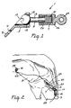
- Adjustable connector 1 comprises anchor 3, pin 5, and cylinder 7.
- Anchor 3 has flange 9 with screw hole 11, which allows anchor 3 to be attached to living bone.
- Anchor 3 also has socket 13 with rounded inner walls that match the curvature of rounded head 15 of pin 5. The rounded walls serve to permit a ready swivel movement of pin 5 within socket 13.
- the axially adjustable member of this embodiment consists of threaded pin 5 and cylinder 7 with a complementary threaded bore.
- Rounded head 15 of pin 5 is accessible and has slot 17 which allows a tool such as a screwdriver, socket wrench, or the like to be inserted to facilitate adjustment of adjustable connector 1.
- Pin 5 also has shaft 19 and threaded end 21 which engages complementary threaded bore 23 of cylinder 7, allowing the position of the pin within the threaded bore to be adjusted by relative rotation of the pin and the cylinder.
- Cylinder 7 has body 25 with threaded bore 23 therein, and bears flutes 27 (as shown in FIG. 2) on its outer surface. Flutes 27 prevent cylinder 7 from turning within the bone tunnel in which it is placed during surgery, insuring that any rotation of pin 5 is translated into axial adjustment of pin 5 within threaded bore 23. Cylinder 7 also has ring 29 at the end opposite threaded bore 23 which ring 29 is adapted to engage the prosthetic ligament. When the other end of the prosthetic ligament is engaged, rotation of pin 5 allows adjustment of tension on the prosthetic ligament without twisting the prosthetic ligament and, as in all embodiments of the invention, without its removal from either of the connectors.
- FIG. 2 is a quarter side view of a human knee joint showing a device of the invention comprising a fixed connector and the adjustable connector of FIG. 1 in place with a prosthetic ligament engaged with both, thus forming a prosthesis for an anterior cruciate ligament.
- a portion of the tibia is shown sectioned so that the cylinder is seen within a bone tunnel.
- anchor 3 of adjustable connector 1 in FIG. 2 is shown attached to tibia 33 in a less than optimal position. In practice, anchor 3 is preferably attached to tibia 33 slightly medial relative to the illustrated point of attachment.
- Tibia 33 has been prepared for the placement of the device by the drilling of bone tunnel 37.
- Adjustable connector 1 and fixed connector 39 (a titanium alloy bobbin in this illustration), have both been attached to bone on opposite sides of the joint by bone screws 41.
- a length of prosthetic ligament 43 which has in this illustration a loop on each end, is engaged with the body of the fixed connector and to ring 29 of adjustable connector 1.
- adjustable connector 1 In the placement of adjustable connector 1 in bone tunnel 37, flutes 27 on cylinder 7 have imparted and/or engaged matching recesses in the wall of bone tunnel 37. Thus when pin 5 is rotated, cylinder 7 cannot rotate with it, but must move axially along the bone tunnel, thus varying the tension on prosthetic ligament 43. It is notable that this embodiment of the device allows continuous, as opposed to incremental, adjustment of tension. Also, it is contemplated that this embodiment of the device can afford relatively easy adjustment of tension if such adjustment becomes necessary after a period of use. Since head 15 of pin 5 is on the tibia, a small incision exposing head 15 can allow adjustment of tension in a relatively minor subsequent surgical procedure.
- a connector comprising an axially adjustable member adapted to engage an anchor and a prosthetic ligament
- the adjustable member is a cylinder with a threaded bone therein and having a rounded head capable of swivel movement within a complementary rounded socket in an anchor
- a complementary threaded pin has a means such as a ring or a hook for engaging a prosthetic ligament
- well known means other than a threaded bore and a complementary threaded pin can be used to achieve axial adjustability.
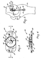
- FIG. 3 is a top view of a second embodiment of the adjustable connector for use in a device of the present invention, wherein the adjustable aspect arises from a spool with a ratchet plate operating in conjunction with an attachment plate.
- adjustable connector 45 comprises spool 47 having ratchet plate 49 attached to the lower side. Means for engaging a prosthetic ligament are needed, and the illustrated variation has loop holes 51 and 53 to provide this function.
- Spool 47 operates in conjunction with attachment plate 55, which is adapted to be attached to living bone, e.g., via bone screws passing through screw holes 57 and 59.
- the attachment plate also has mating surface 61 adapted to engage ratchet plate 49 on spool 47.
- ratchet plate 49 comprises a polygonal plate and mating surface 61 is a polygonal recess that is sized to receive the polygonal plate. Toothed ratchets and other forms of ratchets are also contemplated within the scope of the present invention, but the illustrated embodiment is preferred because it presents the lowest vertical height off the bone so that irritation of nearby structures is minimized.
- Fastening means for fastening spool 47 to attachment plate 55 is required.
- Fastening means preferably have a partially engaged position and a fully engaged position, such that in the partially engaged position, the spool can be rotated to adjust the tension on the prosthetic ligament, but when in the fully engaged position the spool cannot rotate.
- means for fastening comprise holding screw 63, which engages a threaded hole in attachment plate 55. When holding screw 63 is partially loosened, ratchet plate 49 can lift up off mating surface 61 and be rotated freely. When holding screw 63 is fully tightened, ratchet plate 49 is in firm engagement with mating surface 61 and rotation is no longer possible.
- FIG. 4 is a side view of the adjustable connector shown in in FIG. 3.
- mating surface 61 is partially seen at the central edge of attachment plate 55.
- holding screw 63 engages threaded retaining hole 64 in attachment plate 55.
- ratchet plate 49 can lift up off mating surface 61 and rotate freely.
- ratchet plate 49 is in firm engagement with mating surface 61 and rotation is no longer possible.
- spool 47 is seen to include winding shaft 65 around which the prosthetic ligament will be wound in order to take up tension.
- Turning the ratchet plate allows for incremental adjustment of tension. The increments, however, are relatively small since the ratchet plate need be turned only 360/n degrees (where n is the number of sides of the polygonal ratchet plate and mating surface) between increments, and the winding shaft is of relatively small diameter.
- FIG. 5 is a side view of a human knee joint showing a device of the invention comprising a fixed connector and the adjustable connector of FIG. 3 in place with a prosthetic ligament engaged with both, thus forming a prosthesis for a collateral ligament.
- Adjustable connector 45 of this embodiment has been attached to human femur 31 using a pair of bone screws 41.
- Fixed connector 39 has been attached to tibia 33 on the opposite side of the knee joint from adjustable connector 45.
- Prosthetic ligament 43 has been positioned between the fixed connector and the adjustable connector and engages them both. This engagement is provided at the adjustable connector via loop holes 51 and 53 in spool 47.
- Tension has been taken on prosthetic ligament 43 by turning spool 47, wrapping prosthetic ligament 43 about shaft 65 (not seen in this view) of spool 47.
- spool 47 is seen in its fully engaged position, its ratchet plate held immobile against the mating surface in attachment plate 55 by holding screw 63.
- FIG. 6 is a top view of a third embodiment of the adjustable connector for use in a device of the present invention, wherein the adjustable aspect arises from a cleat plate with multiple cleats for variable engagement with the prosthetic ligament.
- adjustable connector 66 comprises cleat plate 67 adapted to be attached to living bone through bone screws passing through screw holes 69.
- cleats 71 are mounted on cleat plate 67 and adapted to engage the prosthetic ligament, for example by having a loop in the end of the prosthetic ligament, which loop slips over the top of a cleat.
- guide hole 73 is provided at one end of cleat plate 67 through which the prosthetic ligament passes.
- FIG. 7 is a side view of the adjustable connector of FIG. 6. This view emphasizes that cleats 71 can have different orientations to allow the surgeon several ways to route the prosthetic ligament.
- FIG. 8 is a side view of a human knee joint showing a device comprising a fixed connector and the adjustable connector of FIG. 6 in place with a prosthetic ligament engaged with both, thus forming a prosthesis for a collateral ligament.
- Adjustable connector 66 of this embodiment has been attached to human femur 31 using a pair of bone screws 41.
- Fixed connector 39 has been attached to tibia 33 on the opposite side of the knee joint from adjustable connector 66.
- Prosthetic ligament 43 been positioned between the fixed connector and the adjustable connector and engages them both. Engagement is provided at the adjustable connector by passing the prosthetic ligament through guide hole 73, around some of the cleats 71 as appropriate, and then looping it over the top of one of the cleats.
- the adjustable and the fixed connectors are fabricated from titanium alloy, most preferably type Ti-6Al-4V (available from Timet Co., Pittsburgh, PA).
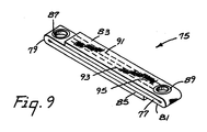
- the prosthetic ligament can be made of any one of a number of different materials, such as braided fiber ropes of a polyolefin, such as polyethylene or polypropylene, or a polyester. It is contemplated that a flat polypropylene braid with a sacrificial layer, as described in commonly assigned U.S. Serial No. 214,699, filed July 1, 1988, would be preferred, particularly for use with the embodiments shown in FIGS. 1 and 2 and FIGS. 6-8. Such a prosthetic ligament is illustrated in FIG. 9. In ligament 75 shown in FIG. 9, a unitary strap-like material is used to form load-bearing strap-like element 77, loops 79 and 81 and sacrificial layers 83 and 85.
- Strap-like element 77 which is the principal load-bearing element of ligament 75, is sandwiched between protective layers having sacrificial areas 83 and 85. Layers 83 and 85 shield load-bearing strap-like element 77 from excessive abrasion at the sites where the ligament contacts bone. In particular, a portion of sacrificial layer 83 extending from approximately the midpoint between eyelets 87 and 89 to near eyelet 87 is positioned between strap-like element 77 and the bone site that element 77 would otherwise contact during use.
- sacrificial layer 85 from about the midpoint of ligament 75 to the end of sacrificial layer 85 near eyelet 89 protects strap-like element 77 from abrasion at another bone site that element 77 would otherwise contact during use.
- Sacrificial layers 83 and 85 are connected or bonded to strap-like element 77.
- Loops 79 and 81 provide additional strength to ligament 75 because eyelets 87 and 89 extend through two layers of material that are folded over to provide continuous fibers at the ends of the device.
- a cylindrical tubular braid would be preferred, particularly such a braid wherein the ends are of a lesser cross-sectional dimension than the rest of the braid.
- a device comprising an adjustable connector of the type illustrated in FIG. 1, was prepared.
- the three main parts of this embodiment of the adjustable connector, the anchor, the pin, and the cylinder, were all fabricated from type Ti-6Al-4V titanium alloy (available from Timet, Co.).
- the socket within the anchor had a spherical radius of .1563 inch (0.3969 cm), the centerline of the hole at the base of the socket was canted at a 45 degree angle to the plane of the flange.
- the rounded head of the pin had a spherical radius of .156 inch (0.40 cm).
- the threaded end of the pin had a #12-28 male thread, matched by the complementary female thread in the threaded bore of the cylinder.
- the cylinder had a maximum outside radius of 0.25 inch (0.64 cm); there were eight flutes on the outside of this cylinder, formed by milling 0.094 inch (0.24 cm) radius troughs longitudinally along the outside surface of the body of the cylinder.
- the fixed connector was a simple cylindrical bobbin with a trough along its circumference for capturing a loop in the prosthetic ligament.
- This bobbin was fabricated from type Ti-6Al-4V titanium alloy (available from Timet, Co.).
- the prosthetic ligament was fabricated as described in Example 3 below from Spectra 1000TM brand polyethylene fiber (commercially available from Allied Chemical Corp., Orlando, VA).
- Example 1 The device of Example 1 was implanted into a human cadaver to replace an injured anterior cruciate ligament.
- the surgery involved the creation of a bone tunnel in the proximal tibia oriented toward the center of the knee joint for the placement of the adjustable connector.
- the prosthetic ligament was then routed from the adjustable connector over the top of the lateral femoral condyle.
- the bobbin used as the fixed connector was attached to the lateral distal femur using a bone screw.
- the adjustable connector was fixed to the tibia generally as depicted in FIG. 2, and one end of the prosthetic ligament was connected to the fixed connector by placing an end loop in the trough around the circumference of the fixed connector.
- the other end of the prosthetic ligament was connected to the adjustable connector by placing the means for engaging the prosthetic ligament, in this case a hook-like member, of the adjustable connector through the other end loop of the prosthetic ligament.
- the tension carried by the prosthetic ligament was adjusted by turning the pin in the adjustable connector using a screwdriver in the slot. The tension was increased slowly until the appropriate joint stability was achieved without inhibiting the range of motion.
- a diamond tubular braid was made with 24 tows of Spectra 1000TM brand polyethylene fiber on a 12 carrier braider (2 tows per carrier). A 25 cm length of braid was used to prepare a prosthetic ligament. To form a loop at each end of the braid, each end of the braid was independently folded back and tucked into an aperture between the loosely braided tows of the tubular braid at a distance of 8.5 cm from the end of the braid. This is a common structure useful for bearing tensile loads. Under a tensile load, the braided tows between which the end of the braid was tucked constrict on the tucked-in end of the braid with sufficient force to keep the tucked-in ends in place, thus maintaining the loops.
- the tucked-in ends were brought together inside the braid, overlapped 3 cm in the middle of the braid, and sewn together.
- the final prosthetic ligament had an overall length of 10 cm with a loop 2 cm in diameter at each end.
- the prosthetic ligament had a tensile strength of 4500 N and a stiffness of 2000 N/mm.
- An abrasion resistant ligament generally of the type shown in FIG. 9 was made as a flat braid constructed from bundles of polypropylene filaments.
- the filaments were formed by die extrusion of a polypropylene resin into a bundle of 180 filaments, each filament being approximately 35 microns in diameter.
- the filament bundle had a tenacity of greater than 7.5 grams per denier.
- the flat braid was then fabricated in an 8 mm width containing 13 bundles of filaments.
- the braid thickness was approximately 1.5 mm.
- the prosthetic ligament was constructed, in accordance with FIG. 9, by folding the braid into three layers and sewing the layers together using polypropylene thread. At the end of the sewing area, the braid was cut and heat sealed to prevent unraveling. Using this procedure, end loops 79 and 81 were formed, one at each end of the prosthetic ligament as shown in FIG. 9. The strength of the prosthetic ligament was determined to be about 3300 N using the loop ends for tensile loading. In this particular example, eyelets 87 and 89, shown in FIG. 9 were not provided.
- the adjustable connector can be connected to such a prosthetic ligament by guiding a hook-like member on the adjustable connector through an eyelet, and a fixed connector can be placed through the opposite eyelet and then attached to bone.
- a hook-like member on the adjustable connector can be guided through the end loop.
Landscapes
- Health & Medical Sciences (AREA)
- Orthopedic Medicine & Surgery (AREA)
- Rehabilitation Therapy (AREA)
- Rheumatology (AREA)
- Cardiology (AREA)
- Oral & Maxillofacial Surgery (AREA)
- Transplantation (AREA)
- Engineering & Computer Science (AREA)
- Biomedical Technology (AREA)
- Heart & Thoracic Surgery (AREA)
- Vascular Medicine (AREA)
- Life Sciences & Earth Sciences (AREA)
- Animal Behavior & Ethology (AREA)
- General Health & Medical Sciences (AREA)
- Public Health (AREA)
- Veterinary Medicine (AREA)
- Prostheses (AREA)
Applications Claiming Priority (2)
| Application Number | Priority Date | Filing Date | Title |
|---|---|---|---|
| US395470 | 1989-08-18 | ||
| US07/395,470 US5002574A (en) | 1989-08-18 | 1989-08-18 | Tensioning means for prosthetic devices |
Publications (2)
| Publication Number | Publication Date |
|---|---|
| EP0413549A2 true EP0413549A2 (de) | 1991-02-20 |
| EP0413549A3 EP0413549A3 (en) | 1992-04-01 |
Family
ID=23563178
Family Applications (1)
| Application Number | Title | Priority Date | Filing Date |
|---|---|---|---|
| EP19900308911 Ceased EP0413549A3 (en) | 1989-08-18 | 1990-08-14 | Tensioning means for prosthetic devices |
Country Status (5)
| Country | Link |
|---|---|
| US (1) | US5002574A (de) |
| EP (1) | EP0413549A3 (de) |
| JP (1) | JPH0392150A (de) |
| AU (1) | AU630214B2 (de) |
| CA (1) | CA2021577A1 (de) |
Cited By (8)
| Publication number | Priority date | Publication date | Assignee | Title |
|---|---|---|---|---|
| WO1995003003A1 (en) * | 1993-07-26 | 1995-02-02 | Desmond Meiring Dall | Bone fixation system |
| GB2288739A (en) * | 1994-04-27 | 1995-11-01 | Corin Medical Ltd | Surgical anchor |
| US5571184A (en) * | 1995-06-07 | 1996-11-05 | Wright Medical Technology, Inc. | Graft fixation device and method of using |
| WO1998033455A1 (en) * | 1997-02-05 | 1998-08-06 | Smith & Nephew, Inc. | Graft attachment device and method of attachment |
| GB2370227A (en) * | 2000-11-21 | 2002-06-26 | Ahmed Mohamed Hosny Khashaba | Ligament tensioning device |
| EP1741410A1 (de) * | 2005-07-04 | 2007-01-10 | Finsbury (Development) Limited | Prothetisches Band |
| GB2454251A (en) * | 2007-11-02 | 2009-05-06 | Biomet Uk Ltd | Artificial ligament with spring biasing and tension adjustment |
| US8470048B2 (en) | 2007-11-02 | 2013-06-25 | Biomet Uk Limited | Prosthesis for simulating natural kinematics |
Families Citing this family (137)
| Publication number | Priority date | Publication date | Assignee | Title |
|---|---|---|---|---|
| US5562668A (en) * | 1990-07-31 | 1996-10-08 | Johnson; David P. | Tension device for anchoring ligament grafts |
| ES2110448T3 (es) * | 1990-09-04 | 1998-02-16 | Hip Dev Pty Ltd | Tornillo quirurgico. |
| US5318575A (en) * | 1992-02-03 | 1994-06-07 | United States Surgical Corporation | Method of using a surgical repair suture product |
| US5507812A (en) * | 1992-12-28 | 1996-04-16 | Moore; David E. | Modular prosthetic ligament |
| ES2185651T3 (es) * | 1993-06-04 | 2003-05-01 | Smith & Nephew Inc | Tornillo quirurgico y arandela. |
| US5843127A (en) * | 1994-08-22 | 1998-12-01 | Le Medical Technologies, Inc. | Fixation device and method for installing same |
| EP0797416B1 (de) * | 1994-12-02 | 2006-03-01 | Omeros Corporation | Reparatursystem für sehnen und bänder |
| US6106556A (en) * | 1994-12-02 | 2000-08-22 | Omeros Medical Systems, Inc. | Tendon and ligament repair system |
| US6235057B1 (en) | 1995-01-24 | 2001-05-22 | Smith & Nephew, Inc. | Method for soft tissue reconstruction |
| US6802862B1 (en) | 1995-01-24 | 2004-10-12 | Smith & Nephew, Inc. | Method for soft tissue reconstruction |
| AUPN238795A0 (en) * | 1995-04-12 | 1995-05-11 | Hip Developments International Pty Ltd | Improved process for knee reconstruction |
| US5702215A (en) * | 1995-06-05 | 1997-12-30 | Li Medical Technologies, Inc. | Retractable fixation device |
| US5643266A (en) * | 1995-06-05 | 1997-07-01 | Li Medical Technologies, Inc. | Method and apparatus for securing ligaments |
| US6117161A (en) * | 1995-06-06 | 2000-09-12 | Li Medical Tecnologies, Inc. | Fastener and fastening method, particularly for fastening sutures to bone |
| US5690649A (en) * | 1995-12-05 | 1997-11-25 | Li Medical Technologies, Inc. | Anchor and anchor installation tool and method |
| NL1005394C1 (nl) * | 1996-04-01 | 1997-10-02 | Kokbing Lo | Bevestigingselement en band bevestigd met bevestigingselement. |
| US5741300A (en) * | 1996-09-10 | 1998-04-21 | Li Medical Technologies, Inc. | Surgical anchor and package and cartridge for surgical anchor |
| US5707395A (en) * | 1997-01-16 | 1998-01-13 | Li Medical Technologies, Inc. | Surgical fastener and method and apparatus for ligament repair |
| JPH1189860A (ja) * | 1997-09-18 | 1999-04-06 | Senko Medical Instr Mfg Co Ltd | 人工靭帯 |
| AUPP000797A0 (en) * | 1997-10-24 | 1997-11-20 | Cryptych Pty Ltd | Fixation of cruciate ligament grafts |
| US6146406A (en) * | 1998-02-12 | 2000-11-14 | Smith & Nephew, Inc. | Bone anchor |
| US6060641A (en) * | 1998-05-14 | 2000-05-09 | Baylor College Of Medicine | Modular mandibular prosthesis |
| US6102934A (en) * | 1998-06-02 | 2000-08-15 | Li; Lehmann K. | Anchor tool and method and apparatus for emplacing anchor in a borehole |
| US6045561A (en) | 1998-06-23 | 2000-04-04 | Orthopaedic Biosystems Ltd., Inc. | Surgical knot manipulator |
| US6221107B1 (en) * | 1998-08-03 | 2001-04-24 | Mark E. Steiner | Ligament fixation device and method |
| US6482210B1 (en) | 1998-11-12 | 2002-11-19 | Orthopaedic Biosystems, Ltd., Inc. | Soft tissue/ligament to bone fixation device with inserter |
| US6299613B1 (en) | 1999-04-23 | 2001-10-09 | Sdgi Holdings, Inc. | Method for the correction of spinal deformities through vertebral body tethering without fusion |
| US6436099B1 (en) * | 1999-04-23 | 2002-08-20 | Sdgi Holdings, Inc. | Adjustable spinal tether |
| US6660022B1 (en) | 1999-06-01 | 2003-12-09 | Smith & Nephew, Inc. | Rotor blade anchor and tool for installing same |
| EP2292167B1 (de) * | 1999-07-07 | 2015-11-25 | Children's Hospital Medical Center | Wirbelsäulenkorrektursystem |
| US6736829B1 (en) | 1999-11-11 | 2004-05-18 | Linvatec Corporation | Toggle anchor and tool for insertion thereof |
| WO2001049190A1 (en) * | 2000-01-03 | 2001-07-12 | Freedland Y | Flip-wing tissue retainer |
| US6451030B2 (en) | 2000-06-30 | 2002-09-17 | Li Medical Technologies, Inc. | Rotor blade anchor and tool for installing same particularlly for arthroscopic installation |
| WO2002030262A2 (en) * | 2000-10-07 | 2002-04-18 | Freedland Y | Orthopedic swivel screw |
| GB0107708D0 (en) * | 2001-03-28 | 2001-05-16 | Imp College Innovations Ltd | Bone fixated,articulated joint load control device |
| US7153327B1 (en) * | 2002-02-25 | 2006-12-26 | Biomet, Inc. | Method and apparatus for mechanically reconstructing ligaments in a knee prosthesis |
| US20040073219A1 (en) * | 2002-10-15 | 2004-04-15 | Skiba Jeffry B. | Insertion instrument |
| US7458981B2 (en) | 2004-03-09 | 2008-12-02 | The Board Of Trustees Of The Leland Stanford Junior University | Spinal implant and method for restricting spinal flexion |
| US8523904B2 (en) | 2004-03-09 | 2013-09-03 | The Board Of Trustees Of The Leland Stanford Junior University | Methods and systems for constraint of spinous processes with attachment |
| US8128658B2 (en) | 2004-11-05 | 2012-03-06 | Biomet Sports Medicine, Llc | Method and apparatus for coupling soft tissue to bone |
| US8840645B2 (en) | 2004-11-05 | 2014-09-23 | Biomet Sports Medicine, Llc | Method and apparatus for coupling soft tissue to a bone |
| US8361113B2 (en) | 2006-02-03 | 2013-01-29 | Biomet Sports Medicine, Llc | Method and apparatus for coupling soft tissue to a bone |
| US8137382B2 (en) | 2004-11-05 | 2012-03-20 | Biomet Sports Medicine, Llc | Method and apparatus for coupling anatomical features |
| US8088130B2 (en) | 2006-02-03 | 2012-01-03 | Biomet Sports Medicine, Llc | Method and apparatus for coupling soft tissue to a bone |
| US8303604B2 (en) | 2004-11-05 | 2012-11-06 | Biomet Sports Medicine, Llc | Soft tissue repair device and method |
| US9017381B2 (en) | 2007-04-10 | 2015-04-28 | Biomet Sports Medicine, Llc | Adjustable knotless loops |
| US7905904B2 (en) | 2006-02-03 | 2011-03-15 | Biomet Sports Medicine, Llc | Soft tissue repair device and associated methods |
| US7909851B2 (en) | 2006-02-03 | 2011-03-22 | Biomet Sports Medicine, Llc | Soft tissue repair device and associated methods |
| US7658751B2 (en) | 2006-09-29 | 2010-02-09 | Biomet Sports Medicine, Llc | Method for implanting soft tissue |
| US7749250B2 (en) | 2006-02-03 | 2010-07-06 | Biomet Sports Medicine, Llc | Soft tissue repair assembly and associated method |
| US8298262B2 (en) | 2006-02-03 | 2012-10-30 | Biomet Sports Medicine, Llc | Method for tissue fixation |
| US9801708B2 (en) | 2004-11-05 | 2017-10-31 | Biomet Sports Medicine, Llc | Method and apparatus for coupling soft tissue to a bone |
| US8118836B2 (en) | 2004-11-05 | 2012-02-21 | Biomet Sports Medicine, Llc | Method and apparatus for coupling soft tissue to a bone |
| US8998949B2 (en) | 2004-11-09 | 2015-04-07 | Biomet Sports Medicine, Llc | Soft tissue conduit device |
| US9072554B2 (en) * | 2005-09-21 | 2015-07-07 | Children's Hospital Medical Center | Orthopedic implant |
| EP1926442A4 (de) * | 2005-09-21 | 2011-06-22 | Childrens Hosp Medical Center | Endoskopische instrumente und verfahren zur abgabe eines wirbelsäulenimplantats |
| US9078644B2 (en) | 2006-09-29 | 2015-07-14 | Biomet Sports Medicine, Llc | Fracture fixation device |
| US8936621B2 (en) | 2006-02-03 | 2015-01-20 | Biomet Sports Medicine, Llc | Method and apparatus for forming a self-locking adjustable loop |
| US8562647B2 (en) | 2006-09-29 | 2013-10-22 | Biomet Sports Medicine, Llc | Method and apparatus for securing soft tissue to bone |
| US8652172B2 (en) | 2006-02-03 | 2014-02-18 | Biomet Sports Medicine, Llc | Flexible anchors for tissue fixation |
| US8597327B2 (en) | 2006-02-03 | 2013-12-03 | Biomet Manufacturing, Llc | Method and apparatus for sternal closure |
| US8801783B2 (en) | 2006-09-29 | 2014-08-12 | Biomet Sports Medicine, Llc | Prosthetic ligament system for knee joint |
| US11311287B2 (en) | 2006-02-03 | 2022-04-26 | Biomet Sports Medicine, Llc | Method for tissue fixation |
| US8251998B2 (en) | 2006-08-16 | 2012-08-28 | Biomet Sports Medicine, Llc | Chondral defect repair |
| US9538998B2 (en) | 2006-02-03 | 2017-01-10 | Biomet Sports Medicine, Llc | Method and apparatus for fracture fixation |
| US8652171B2 (en) | 2006-02-03 | 2014-02-18 | Biomet Sports Medicine, Llc | Method and apparatus for soft tissue fixation |
| US11259792B2 (en) | 2006-02-03 | 2022-03-01 | Biomet Sports Medicine, Llc | Method and apparatus for coupling anatomical features |
| US8562645B2 (en) | 2006-09-29 | 2013-10-22 | Biomet Sports Medicine, Llc | Method and apparatus for forming a self-locking adjustable loop |
| US8506597B2 (en) | 2011-10-25 | 2013-08-13 | Biomet Sports Medicine, Llc | Method and apparatus for interosseous membrane reconstruction |
| US9149267B2 (en) | 2006-02-03 | 2015-10-06 | Biomet Sports Medicine, Llc | Method and apparatus for coupling soft tissue to a bone |
| US8771352B2 (en) | 2011-05-17 | 2014-07-08 | Biomet Sports Medicine, Llc | Method and apparatus for tibial fixation of an ACL graft |
| US10517587B2 (en) | 2006-02-03 | 2019-12-31 | Biomet Sports Medicine, Llc | Method and apparatus for forming a self-locking adjustable loop |
| US8968364B2 (en) | 2006-02-03 | 2015-03-03 | Biomet Sports Medicine, Llc | Method and apparatus for fixation of an ACL graft |
| US8574235B2 (en) | 2006-02-03 | 2013-11-05 | Biomet Sports Medicine, Llc | Method for trochanteric reattachment |
| AT504039A1 (de) * | 2006-07-27 | 2008-02-15 | Univ Wien Med | Implantat zur befestigung von bändern oder sehnen |
| US8672969B2 (en) | 2006-09-29 | 2014-03-18 | Biomet Sports Medicine, Llc | Fracture fixation device |
| US9918826B2 (en) | 2006-09-29 | 2018-03-20 | Biomet Sports Medicine, Llc | Scaffold for spring ligament repair |
| US8500818B2 (en) | 2006-09-29 | 2013-08-06 | Biomet Manufacturing, Llc | Knee prosthesis assembly with ligament link |
| US11259794B2 (en) | 2006-09-29 | 2022-03-01 | Biomet Sports Medicine, Llc | Method for implanting soft tissue |
| WO2008051801A2 (en) * | 2006-10-19 | 2008-05-02 | Simpirica Spine, Inc. | Structures and methods for constraining spinal processes with single connector |
| US20080262549A1 (en) * | 2006-10-19 | 2008-10-23 | Simpirica Spine, Inc. | Methods and systems for deploying spinous process constraints |
| US8162982B2 (en) | 2006-10-19 | 2012-04-24 | Simpirica Spine, Inc. | Methods and systems for constraint of multiple spine segments |
| US8187307B2 (en) | 2006-10-19 | 2012-05-29 | Simpirica Spine, Inc. | Structures and methods for constraining spinal processes with single connector |
| US8029541B2 (en) | 2006-10-19 | 2011-10-04 | Simpirica Spine, Inc. | Methods and systems for laterally stabilized constraint of spinous processes |
| US12502169B2 (en) | 2007-01-16 | 2025-12-23 | Biomet Sports Medicine, Llc | Soft tissue repair device and associated methods |
| US20080275557A1 (en) * | 2007-05-01 | 2008-11-06 | Exploramed Nc4, Inc. | Adjustable absorber designs for implantable device |
| US20110245928A1 (en) | 2010-04-06 | 2011-10-06 | Moximed, Inc. | Femoral and Tibial Bases |
| US7678147B2 (en) * | 2007-05-01 | 2010-03-16 | Moximed, Inc. | Extra-articular implantable mechanical energy absorbing systems and implantation method |
| US9907645B2 (en) | 2007-05-01 | 2018-03-06 | Moximed, Inc. | Adjustable absorber designs for implantable device |
| US10022154B2 (en) * | 2007-05-01 | 2018-07-17 | Moximed, Inc. | Femoral and tibial base components |
| US8894714B2 (en) | 2007-05-01 | 2014-11-25 | Moximed, Inc. | Unlinked implantable knee unloading device |
| US8709090B2 (en) | 2007-05-01 | 2014-04-29 | Moximed, Inc. | Adjustable absorber designs for implantable device |
| US20100137996A1 (en) * | 2007-05-01 | 2010-06-03 | Moximed, Inc. | Femoral and tibial base components |
| US8123805B2 (en) | 2007-05-01 | 2012-02-28 | Moximed, Inc. | Adjustable absorber designs for implantable device |
| US20080275567A1 (en) | 2007-05-01 | 2008-11-06 | Exploramed Nc4, Inc. | Extra-Articular Implantable Mechanical Energy Absorbing Systems |
| US20110172708A1 (en) * | 2007-06-22 | 2011-07-14 | Simpirica Spine, Inc. | Methods and systems for increasing the bending stiffness of a spinal segment with elongation limit |
| US20100036424A1 (en) | 2007-06-22 | 2010-02-11 | Simpirica Spine, Inc. | Methods and systems for increasing the bending stiffness and constraining the spreading of a spinal segment |
| EP2182864B1 (de) * | 2007-06-22 | 2016-06-08 | Empirical Spine, Inc. | Vorrichtungen zur kontrollierten flexionsbegrenzung von wirbelsäulensegmenten |
| US7905918B2 (en) * | 2007-08-23 | 2011-03-15 | William Wayne Cimino | Elastic metallic replacement ligament |
| US8118868B2 (en) * | 2008-04-22 | 2012-02-21 | Biomet Manufacturing Corp. | Method and apparatus for attaching soft tissue to an implant |
| US20090265015A1 (en) * | 2008-04-22 | 2009-10-22 | Biomet Manufacturing Corp. | Method And Apparatus For Attaching Soft Tissue To Bone |
| EP2326267B1 (de) * | 2008-06-06 | 2018-04-25 | Empirical Spine, Inc. | Geräte zur arretierung eines implantierbaren bands |
| EP2296566A4 (de) | 2008-06-06 | 2013-01-02 | Simpirica Spine Inc | Verfahren und gerät zur ablage von wirbelfortsatz-halterungen |
| US12245759B2 (en) | 2008-08-22 | 2025-03-11 | Biomet Sports Medicine, Llc | Method and apparatus for coupling soft tissue to bone |
| US12419632B2 (en) | 2008-08-22 | 2025-09-23 | Biomet Sports Medicine, Llc | Method and apparatus for coupling anatomical features |
| JP2012520131A (ja) * | 2009-03-10 | 2012-09-06 | シンピライカ スパイン, インコーポレイテッド | 外科用テザー装置および使用方法 |
| EP2405840B1 (de) | 2009-03-10 | 2024-02-21 | Empirical Spine, Inc. | Chirurgische gurtvorrichtung |
| WO2010104975A1 (en) | 2009-03-10 | 2010-09-16 | Simpirica Spine, Inc. | Surgical tether apparatus and methods of use |
| US8668719B2 (en) * | 2009-03-30 | 2014-03-11 | Simpirica Spine, Inc. | Methods and apparatus for improving shear loading capacity of a spinal segment |
| US20100305710A1 (en) | 2009-05-28 | 2010-12-02 | Biomet Manufacturing Corp. | Knee Prosthesis |
| US12096928B2 (en) | 2009-05-29 | 2024-09-24 | Biomet Sports Medicine, Llc | Method and apparatus for coupling soft tissue to a bone |
| US12551209B2 (en) | 2009-06-22 | 2026-02-17 | Biomet Sports Medicine, Llc | Method and apparatus for coupling soft tissue to a bone |
| US9668868B2 (en) | 2009-08-27 | 2017-06-06 | Cotera, Inc. | Apparatus and methods for treatment of patellofemoral conditions |
| CN116570353A (zh) * | 2009-08-27 | 2023-08-11 | 铸造有限责任公司 | 用于改变膝关节中髌骨与股骨之间的负载及治疗髋关节疾病的设备 |
| US9861408B2 (en) | 2009-08-27 | 2018-01-09 | The Foundry, Llc | Method and apparatus for treating canine cruciate ligament disease |
| US10349980B2 (en) | 2009-08-27 | 2019-07-16 | The Foundry, Llc | Method and apparatus for altering biomechanics of the shoulder |
| US9278004B2 (en) | 2009-08-27 | 2016-03-08 | Cotera, Inc. | Method and apparatus for altering biomechanics of the articular joints |
| US8523943B2 (en) * | 2009-11-02 | 2013-09-03 | Karl Storz Gmbh & Co. Kg | Method and device for the fixation of a tendon graft |
| US9044270B2 (en) | 2011-03-29 | 2015-06-02 | Moximed, Inc. | Apparatus for controlling a load on a hip joint |
| US12329373B2 (en) | 2011-05-02 | 2025-06-17 | Biomet Sports Medicine, Llc | Method and apparatus for soft tissue fixation |
| US9357991B2 (en) | 2011-11-03 | 2016-06-07 | Biomet Sports Medicine, Llc | Method and apparatus for stitching tendons |
| US12582395B2 (en) | 2011-11-03 | 2026-03-24 | Biomet Sports Medicine, Llc | Method and apparatus for forming a self-locking adjustable loop |
| US9381013B2 (en) | 2011-11-10 | 2016-07-05 | Biomet Sports Medicine, Llc | Method for coupling soft tissue to a bone |
| US9314241B2 (en) | 2011-11-10 | 2016-04-19 | Biomet Sports Medicine, Llc | Apparatus for coupling soft tissue to a bone |
| US9370350B2 (en) | 2011-11-10 | 2016-06-21 | Biomet Sports Medicine, Llc | Apparatus for coupling soft tissue to a bone |
| US9468466B1 (en) | 2012-08-24 | 2016-10-18 | Cotera, Inc. | Method and apparatus for altering biomechanics of the spine |
| US9757119B2 (en) | 2013-03-08 | 2017-09-12 | Biomet Sports Medicine, Llc | Visual aid for identifying suture limbs arthroscopically |
| US9918827B2 (en) | 2013-03-14 | 2018-03-20 | Biomet Sports Medicine, Llc | Scaffold for spring ligament repair |
| GB2517153A (en) | 2013-08-15 | 2015-02-18 | Biomet Uk Healthcare Ltd | Ligament assembly |
| US10136886B2 (en) | 2013-12-20 | 2018-11-27 | Biomet Sports Medicine, Llc | Knotless soft tissue devices and techniques |
| US9615822B2 (en) | 2014-05-30 | 2017-04-11 | Biomet Sports Medicine, Llc | Insertion tools and method for soft anchor |
| US9700291B2 (en) | 2014-06-03 | 2017-07-11 | Biomet Sports Medicine, Llc | Capsule retractor |
| US9724110B2 (en) | 2014-08-01 | 2017-08-08 | J. Dean Cole | System and method for load balancing in knee replacement procedures |
| US10039543B2 (en) | 2014-08-22 | 2018-08-07 | Biomet Sports Medicine, Llc | Non-sliding soft anchor |
| US9955980B2 (en) | 2015-02-24 | 2018-05-01 | Biomet Sports Medicine, Llc | Anatomic soft tissue repair |
| US9974534B2 (en) | 2015-03-31 | 2018-05-22 | Biomet Sports Medicine, Llc | Suture anchor with soft anchor of electrospun fibers |
| EP3235471A1 (de) * | 2016-04-22 | 2017-10-25 | Kyon AG | Implantatsystem zur reparatur oder zum ersatz von spannungstragendem bindegewebe |
Family Cites Families (17)
| Publication number | Priority date | Publication date | Assignee | Title |
|---|---|---|---|---|
| FR2213761B1 (de) * | 1973-01-17 | 1976-05-14 | Rambert Andre | |
| US3953896A (en) * | 1974-09-06 | 1976-05-04 | Richards Manufacturing Company, Inc. | Prosthetic ligament |
| US4246660A (en) * | 1978-12-26 | 1981-01-27 | Queen's University At Kingston | Artificial ligament |
| CA1112401A (en) * | 1979-05-24 | 1981-11-17 | Roland Dore | Deformable high energy storage tension spring |
| CH644748A5 (de) * | 1980-06-03 | 1984-08-31 | Sulzer Ag | Sehnen- und/oder baenderersatzmaterial. |
| US4744793A (en) * | 1985-09-06 | 1988-05-17 | Zimmer, Inc. | Prosthetic ligament connection assembly |
| US4708132A (en) * | 1986-01-24 | 1987-11-24 | Pfizer-Hospital Products Group, Inc. | Fixation device for a ligament or tendon prosthesis |
| US4712542A (en) * | 1986-06-30 | 1987-12-15 | Medmetric Corporation | System for establishing ligament graft orientation and isometry |
| US4776851A (en) * | 1986-07-23 | 1988-10-11 | Bruchman William C | Mechanical ligament |
| SU1419690A1 (ru) * | 1986-10-08 | 1988-08-30 | Запорожский Областной Отдел Здравоохранения | Фиксатор дл остеосинтеза |
| FR2605513B1 (fr) * | 1986-10-28 | 1989-06-16 | Cerol Bandeira Maria | Dispositif d'ancrage sur un os d'une prothese ligamentaire ou tendineuse munie de ganses d'extremite, et ensemble de prothese comportant un tel dispositif |
| US4772286A (en) * | 1987-02-17 | 1988-09-20 | E. Marlowe Goble | Ligament attachment method and apparatus |
| DE3710587A1 (de) * | 1987-03-31 | 1988-10-20 | Witzel Ulrich | Knieband-ersatz |
| SU1475628A1 (ru) * | 1987-08-17 | 1989-04-30 | Запорожский Областной Отдел Здравоохранения | Внутрикостный компрессирующий винт |
| US4940467A (en) * | 1988-02-03 | 1990-07-10 | Tronzo Raymond G | Variable length fixation device |
| US4828562A (en) * | 1988-02-04 | 1989-05-09 | Pfizer Hospital Products Group, Inc. | Anterior cruciate ligament prosthesis |
| US4955910A (en) * | 1989-07-17 | 1990-09-11 | Boehringer Mannheim Corporation | Fixation system for an elongated prosthesis |
-
1989
- 1989-08-18 US US07/395,470 patent/US5002574A/en not_active Expired - Fee Related
-
1990
- 1990-07-19 CA CA002021577A patent/CA2021577A1/en not_active Abandoned
- 1990-07-30 AU AU59999/90A patent/AU630214B2/en not_active Ceased
- 1990-08-14 EP EP19900308911 patent/EP0413549A3/en not_active Ceased
- 1990-08-17 JP JP2216943A patent/JPH0392150A/ja active Pending
Cited By (15)
| Publication number | Priority date | Publication date | Assignee | Title |
|---|---|---|---|---|
| WO1995003003A1 (en) * | 1993-07-26 | 1995-02-02 | Desmond Meiring Dall | Bone fixation system |
| GB2288739A (en) * | 1994-04-27 | 1995-11-01 | Corin Medical Ltd | Surgical anchor |
| US5571184A (en) * | 1995-06-07 | 1996-11-05 | Wright Medical Technology, Inc. | Graft fixation device and method of using |
| WO1998033455A1 (en) * | 1997-02-05 | 1998-08-06 | Smith & Nephew, Inc. | Graft attachment device and method of attachment |
| GB2370227A (en) * | 2000-11-21 | 2002-06-26 | Ahmed Mohamed Hosny Khashaba | Ligament tensioning device |
| GB2370227B (en) * | 2000-11-21 | 2002-11-06 | Ahmed Mohamed Hosny Khashaba | Khashaba Tensioner 1 (KT1) |
| EP1741410A1 (de) * | 2005-07-04 | 2007-01-10 | Finsbury (Development) Limited | Prothetisches Band |
| GB2454251A (en) * | 2007-11-02 | 2009-05-06 | Biomet Uk Ltd | Artificial ligament with spring biasing and tension adjustment |
| GB2454251B (en) * | 2007-11-02 | 2011-04-06 | Biomet Uk Ltd | Prosthesis comprising an artificial ligament |
| US8470048B2 (en) | 2007-11-02 | 2013-06-25 | Biomet Uk Limited | Prosthesis for simulating natural kinematics |
| US8998993B2 (en) | 2007-11-02 | 2015-04-07 | Biomet Uk Limited | Prosthesis for stimulating natural kinematics |
| US9381079B2 (en) | 2007-11-02 | 2016-07-05 | Biomet Uk Limited | Prosthesis for stimulating natural kinematics |
| US9433494B2 (en) | 2007-11-02 | 2016-09-06 | Biomet Uk Limited | Prosthesis for simulating natural kinematics |
| US9675441B2 (en) | 2007-11-02 | 2017-06-13 | Biomet Uk Limited | Prosthesis for simulating natural kinematics |
| US10531948B2 (en) | 2007-11-02 | 2020-01-14 | Biomet Uk Limited | Prosthesis for simulating natural kinematics |
Also Published As
| Publication number | Publication date |
|---|---|
| JPH0392150A (ja) | 1991-04-17 |
| AU5999990A (en) | 1991-02-21 |
| CA2021577A1 (en) | 1991-02-19 |
| AU630214B2 (en) | 1992-10-22 |
| US5002574A (en) | 1991-03-26 |
| EP0413549A3 (en) | 1992-04-01 |
Similar Documents
| Publication | Publication Date | Title |
|---|---|---|
| US5002574A (en) | Tensioning means for prosthetic devices | |
| US5108433A (en) | Tensioning means for prosthetic devices | |
| AU2019271884B2 (en) | Implant having adjustable filament coils | |
| US8591578B2 (en) | Adjustable suture-button constructs for ligament reconstruction | |
| EP0304268B1 (de) | Permanente Bandprothese | |
| US4790850A (en) | Phosthetic ligament | |
| US20120109194A1 (en) | Suspensory graft fixation with adjustable loop length | |
| EP3678590B1 (de) | Zwei-wege-verstellbare schleifensuspensoriumsvorrichtung zur fixierung eines weichteiltransplantats | |
| US20220361867A1 (en) | Knotless soft tissue implant systems and related methods | |
| CA3118463A1 (en) | Surgical fixation systems and associated methods for performing tissue repairs | |
| EP3886727B1 (de) | Implantatanordnung und verfahren zu deren herstellung | |
| EP0349324A1 (de) | Abnützungsresistente Prothesenvorrichtung |
Legal Events
| Date | Code | Title | Description |
|---|---|---|---|
| PUAI | Public reference made under article 153(3) epc to a published international application that has entered the european phase |
Free format text: ORIGINAL CODE: 0009012 |
|
| AK | Designated contracting states |
Kind code of ref document: A2 Designated state(s): AT CH DE ES FR GB IT LI NL SE |
|
| 17P | Request for examination filed |
Effective date: 19910102 |
|
| PUAL | Search report despatched |
Free format text: ORIGINAL CODE: 0009013 |
|
| AK | Designated contracting states |
Kind code of ref document: A3 Designated state(s): AT CH DE ES FR GB IT LI NL SE |
|
| 17Q | First examination report despatched |
Effective date: 19930809 |
|
| STAA | Information on the status of an ep patent application or granted ep patent |
Free format text: STATUS: THE APPLICATION HAS BEEN REFUSED |
|
| 18R | Application refused |
Effective date: 19950831 |