EP0413575A2 - Imprimante pour caractères - Google Patents
Imprimante pour caractères Download PDFInfo
- Publication number
- EP0413575A2 EP0413575A2 EP90308978A EP90308978A EP0413575A2 EP 0413575 A2 EP0413575 A2 EP 0413575A2 EP 90308978 A EP90308978 A EP 90308978A EP 90308978 A EP90308978 A EP 90308978A EP 0413575 A2 EP0413575 A2 EP 0413575A2
- Authority
- EP
- European Patent Office
- Prior art keywords
- type
- drum
- selection
- gear
- printer
- Prior art date
- Legal status (The legal status is an assumption and is not a legal conclusion. Google has not performed a legal analysis and makes no representation as to the accuracy of the status listed.)
- Withdrawn
Links
Images










Classifications
-
- B—PERFORMING OPERATIONS; TRANSPORTING
- B41—PRINTING; LINING MACHINES; TYPEWRITERS; STAMPS
- B41J—TYPEWRITERS; SELECTIVE PRINTING MECHANISMS, i.e. MECHANISMS PRINTING OTHERWISE THAN FROM A FORME; CORRECTION OF TYPOGRAPHICAL ERRORS
- B41J1/00—Typewriters or selective printing mechanisms characterised by the mounting, arrangement or disposition of the types or dies
- B41J1/22—Typewriters or selective printing mechanisms characterised by the mounting, arrangement or disposition of the types or dies with types or dies mounted on carriers rotatable for selection
- B41J1/32—Typewriters or selective printing mechanisms characterised by the mounting, arrangement or disposition of the types or dies with types or dies mounted on carriers rotatable for selection the plane of the type or die face being parallel to the axis of rotation, e.g. with type on the periphery of cylindrical carriers
- B41J1/44—Carriers stationary for impression
Definitions
- This invention relates to type printers e.g. those used in calculators, cash registers, etc., and more particularly those used in applications requiring high speed printing or two-colour printing.
- type drum printers are generally highly functional printers capable of high speed printing by means of simultaneous printing of multiple columns, and in recent years, market demand for multiple colour printing and faster printing has grown.
- JP-A-61-164865 a printer was disclosed in which one line of printing was effected by a type drum which was rotated once, and the type drum was restricted from moving in the column direction.
- the type drum was driven by a step motor, and the printer was provided with a reset pulse detector which detected the reference phase
- the type on the type drum could print on the paper or other record medium only at their respective corresponding column positions, and basically only the same colour ink could be applied to all of the type on the type drum. Consequently, in principle, it was impossible to freely print with multiple colours at any desired column. Further, a reset pulse detector was required for detecting the reference phase of the step motor, and the step motor itself was expensive. Also, complicated speed adjustment was required to achieve high speed printing, so that many demands were made on control, and since the step motor itself was not efficient, current consumption was high, which led to more expensive drive circuits.
- the type drum and the rotation of the detection mechanism would stop for type selection, so that hammer drive during the printing process; i.e. powering of the print electromagnet, could not be performed in synchronism with the timing pulse. Therefore, powering of the print electromagnet was based on timing determined by a reference clock generated by the control circuit and software. This increased the load on the control circuit, and since the reference clock frequency had to be highly precise to realize stable operation timing, circuit costs were increased.
- vibration or rotational fluctuation would generally occur when the type drum stopped and started, causing the type to vibrate during printing so as to impair printing quality.
- rotational fluctuations immediately after driving the type drum would cause incorrect selection at the next type selection, so that there were still a number of troublesome problems.
- These phenomena became more apparent at faster printing speeds, so that they limited the speed at which type printers could print.
- the type drum and motor each required much space, and the selection mechanism was disposed separately, so that there was a limit to how small the printer could be made. Since the motor was exposed, its noise was audible during motor operation.
- a type printer comprising rotatably mounted drum or ring-shaped type-bearing means; a motor for rotating the type-bearing means; and selection means which is arranged to selectively permit and prevent rotation of the type-bearing means by the motor characterised by detection means which continually generates a timing signal during rotation of the motor, the timing signal being arranged to control the selection means.
- print-effecting means for forcing selected type on the type-bearing means into a printing position, the said timing signal being arranged to operate the print-effecting means in synchronism with the operation of the selection means.
- the print-effecting means preferably comprise hammers disposed within the type-bearing means.
- shift means for alternately shifting the type-bearing means in the column direction each time the type-bearing means completes one revolution.
- Ink rollers are preferably provided for respectively applying a plurality of differently coloured inks in alternate revolutions of the type-bearing means.
- stop release means which are arranged to release the automatic stop means at the beginning of printing a line.
- the respective functions of the selection means and of the stop release means are combined in a single selection/stop release means which is controlled by a single trigger mechanism.
- damping means are provided for suppressing vibration of the type-bearing means during operation of the selection means.
- the damping means may comprise an inertia wheel and a damper spring secured to the latter.
- the type-bearing means may comprise a type drum provided with a drum gear, the motor being housed within the type drum or drum gear.
- the motor may be part-cylindrical so as to leave a space between itself and the type drum or drum gear within which it is housed, the print-effecting means having a part which passes through said space.
- the invention offers a compact, low power, low noise, high speed drum printer at low cost which does not use a step motor, reset pulse detector and other expensive parts, the drive of the printer being by means of an extremely simple control method and low cost drive circuit so that low cost control circuits and software can be used.
- the invention offers a fast, highly reliable type printer which suppresses vibration or rotational fluctuation in the type drum and thereby prevents degradation of the print quality due to vibration during printing or incorrect selection in the next type selection due to rotational fluctuation immediately after driving the type drum.
- the type drum to which at least two colours of ink are applied alternately in the column direction, is alternately shifted in the column direction after each rotation, and then the type drum is automatically stopped when it has rotated twice.
- the selection and stop release means rotates the type drum and performs selection, and it also releases the automatically stopped state of the type drum at the beginning of printing of a line.
- the selection means is controlled by the powering of the trigger mechanism in synchronisation with a pulse generated by the detection means and corresponding to the type position on the type drum. This series of operations is performed by the power of the motor (e.g. a compact DC motor) which serves as the drive source.
- a timing pulse is generated by the detection means when the type drum is stopped, drive of the hammers in the printing process; i.e. powering of a print electromagnet, can be performed in synchronisation with the timing pulse. Also, this timing pulse can be used to count the type position and determine the drive timing for the selection means during rotation of the type drum.
- the damper or inertia wheel rotates continuously at a constant speed due to inertia, so that if vibration or rotational fluctuation occurs in the type drum, an angular velocity difference occurs between the type drum and the damper wheel. This angular velocity difference generates friction torque at the contact surface between the damper spring and the damper wheel, and this acts to suppress vibration or rotational fluctuation in the type drum.
- the above configuration of this invention also makes it possible to use the wasted space in the type drum or the drum gear, which makes up part of the selection mechanism, as a housing space for the motor, so that the printer can be made more compact.
- One end of the yoke of the print electromagnet passes through the space between the inside of the type drum or the drum gear and the outside of the motor, so that the print electromagnet inside the type drum can also be secured to the printer body. Also, the rotational noise generated by the motor is shielded by the type drum or the drum gear.
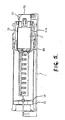
- FIGs 1 and 2 there is shown a type printer according to the present invention which has a frame 1 provided with a hole 1-a, a groove 1-b and a stopper 1-c.
- a drum gear 2 has a ratchet 2-a ( Figure 6), a notched gear 2-b, a key groove 2-c (at four positions around the circumference) and a shaft 2-d, and it is supported by a No. 1 bearing 13 and a key 3-c ( Figure 6) at four positions around the circumference) of a type drum 3.
- the drum gear 2 and the type drum 3 rotate in the same phase because they are interlocked by the key groove 2-c and the key 3-c.
- the type drum 3 comprises cam grooves 3-a ( Figure 6), a groove 3-b, the key 3-c and a paper feed drive gear 3-d in a single unit, and has through-holes 3-e in its outer circumference.
- the type drum 3 is supported by a No. 2 bearing 14 and an intermediate bearing 48.
- a type sheet 4 has type 4-a arranged in a staggered pattern on its outer surface and it has projections 4-b on its inner surface corresponding to each of the type 4-a.
- the projections 4-c at opposite ends of the type sheet 4 in the circumferential direction are inserted in the through-holes 3-e and the type sheet 4 is wrapped around the type drum 3.
- Print yokes 5 and 6 constitute the yokes of a print electromagnet.
- a print core 7 ( Figure 4) is fixed to the print yoke 6, and there is one print coil 8 allotted to every two columns of type 4-a.
- Hammers 9 are set inside the print coils 8 so that they can slide.
- One end 5-a of the print yoke 5 extends below a compact DC motor 11 and through the No. 1 bearing 13 and the No. 2 bearing 14, and opposite ends of the print yoke 5 are secured to the frame 1 by screws.
- the drum gear 2 and the bearings 13 and 14 cannot move in the column direction, but the type drum 3 can shift a prescribed amount in the column direction.
- the DC motor 11 which is approximately 20 mm in diameter, is mounted inside the drum gear 2 with a gap between the two.
- the drum gear 2 can turn on the No. 1 bearing 13, but the DC motor 11 is secured by the No. 1 bearing 13 and the intermediate bearing 48 so that it cannot turn.
- the motor 11 is distinguished by flat top and bottom surfaces (so-called "double D cut").
- a damper or inertia wheel 53 is pushed toward the upper place columns by a damper spring 54 (see Figure 17(a) and (b)).
- the damper wheel 53 and the damper spring 54 make up a damping mechanism for suppressing rotational fluctuation of the type drum 3.
- a rotor 12 comprises a shift mechanism which pivots in the hole 1-a in the frame 1 and fits in the cam groove 3-a in the type drum 3 to shift the type drum 3 one column in the column direction once every rotation.
- An ink roller cover 15 ( Figure 3) is supported by an ink roller shaft 16.
- An ink roller holder 17 is inserted in alternating black ink rollers 18 and red ink rollers 19 and slides freely on the ink roller shaft 16, and a positioning part 17-a of the ink roller holder 17 fits in a groove 16-a on the ink roller shaft 16 and shifts the ink rollers 18 and 19 in the column direction.
- a paper feed shaft 20 passes through a paper feed roller 21 and is supported by a platen 22 attached to the frame 1.
- the platen 22 is positioned from front to rear and from left to right by a pin 1-f on the frame 1, and it is secured in the vertical direction by a snap hook 1-g.
- a paper feed gear 23 is pushed against the paper feed shaft 20 by a paper feed spring 24.
- the secured end of the paper feed spring 24 is press fitted in the groove 1-e in the top of the frame 1.
- the paper feed gear 23 and the paper feed shaft 20 fit together to make up a one-way clutch by means of triangular teeth. Consequently, the paper feed gear 23 firmly drives the paper feed shaft 20 when rotating in the paper feed direction.
- the paper feed gear 23 is a three-stage intermittent gear, and it intermittently meshes with the paper feed drive gear 3-d formed on the type drum 3 each time the type drum 3 shifts when it rotates twice (see Figure 13, Figure 14 and Figure 15).
- a paper presser shaft 26, which is supported at opposite ends thereof by the frame 1, is inserted in a paper presser roller 25, which presses the printing paper (not shown) against the paper feed roller 21 by the spring force of the paper presser shaft 26.
- a cushion roller 50 and a cushion spring 51 make up a cushion mechanism for cushioning impacts on the printing paper during the paper feed process, and the cushion roller 50 can move up and down in a groove 1-d in the frame 1 but is pushed upwards by the cushion spring 51.
- a paper exit holder 52 ( Figure 4) regulates the direction of travel of the printed paper at the paper exit position, and a paper exit presser 58 (Figure 2) presses the printing paper against the printing surface 22-a of the platen 22 just before the printing position (see Figure 4). Both the paper exit holder 52 and the paper exit presser 58 are secured by snap fitting on the platen 22.
- An interlock frame 29 shifts together with the type drum 3 as a unit along the groove 1-b in the frame 1 by means of a projection 29-a fitting in the groove 3-b ( Figure 6) in the type drum 3.
- Ink roller springs 30 ( Figure 2) press the ink rollers 18 and 19 against the type drum 3.
- the power of the DC motor 11 is transferred from a motor gear 32 to a reduction gear 34 via a transfer gear 33 (see Figure 7).
- Each of the gears 32-34 turn consecutively in the directions indicated by the arrows in Figure 7.
- a detection plate 34-b and a sun gear 34-c are formed together with the reduction gear 34 as one unit.
- a drum drive gear 35 ( Figures 2 and 3) is formed as a unit together with shafts 35-a which support planet gears 36, a ratchet 35-b ( Figure 10) split in the circumferential direction at a position corresponding to the type position, and a gear 35-c, and the drum drive gear 35 is supported by the reduction gear 34.
- the gear 35-c of the drum drive gear 35 meshes with the teeth 2-g of the drum gear 2.
- a selection cam 37 is formed as a unit together with an inside gear 37-a, a slide cam 37-b ( Figure 2), a control cam 37-c and a detent cam 37-d (see Figure 8 and Figure 9).
- the gear train formed by the inside gear 37-a, the planet gears 36 and the sun gear 34-c comprises a so-called "sun-and-planet differential mechanism".
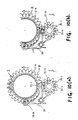
- This sun-and-plant differential mechanism which operates in the two modes shown respectively in Figure 8 (a), i.e. with a fixed inside gear 37-a, and Figure 8 (b), i.e. with a fixed drum drive gear shaft 35-a, rotates in the directions indicated by the arrows in the Figures 8(a) and 8(b).
- the mechanism operates in the mode shown in Figure 8 (a) except during selection, and it operates in the mode in Figure 8 (b) during selection.
- the reduction gear 34 and the selection cam 37 are supported by a shaft 38.
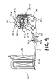
- a selection lever 39 pivots at either end in the No. 1 bearing 13 and the frame 1, and acts on the above-mentioned sun-and-planet differential mechanism to switch between type selection and power transfer.
- the selection lever 39 is formed as a unit together with a groove 39-a in which fits one end of a trigger attraction plate 47, described below.
- the selection lever 39 is also formed as a unit with a claw 39-b which engages the ratchet 2-a of the drum gear 2 and holds the drum gear 2 during type drum selection.
- the selection lever 39 has a pin 39-d which engages the control cam 37-c on the selection cam 37, and a detent 39-c (see Figure 9 and Figure 10).
- a detent spring 40 acts on the detent 39-c of the selection lever 39 and on the detent cam 37-d of the selection cam 37 to position them (detent action).
- the detent spring 40 is attached to the frame 1 by press fitting an attachment part thereof in a groove 1-h ( Figure 2) in the frame 1.
- the sun-and-planet differential mechanism 37-a, 36, 34-c, the selection lever 39 and the detent spring 40 described above constitute a selection mechanism which rotates and selectively stops the drum gear 2 and the type drum 3.
- the selection mechanism also has the function of releasing an automatic stop mechanism described below.
- a photodetector 41 ( Figure 1) constitutes a detection means which is snap fitted to the No. 1 bearing 13, and it generates three timing pulses each time the reduction gear 34 rotates.
- Slide teeth 42 have a stopper 42-a, and they are set so that they can slide on the drum gear 2 and receive the spring force of a slide spring 44 on the side toward the upper place columns (see Figure 12).
- a retention claw 43 is supported by the shaft 2-d of the drum gear 2 and receives a rotational force from the slide spring 44.
- the retention claw 43 has a cam 43-a and a stopper 43-b.
- the slide teeth 42, retention claw 43, slide spring 44 and the above-mentioned stopper 1-c of the frame 1 make up an automatic stopping means which stops the type drum 3 in its initial phase.
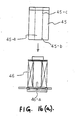
- a trigger yoke 45 which constitutes the yoke of a trigger electromagnet, is press fitted in a centre hole of a trigger coil 46 as shown in Figure 16 (a).
- a reverse claw 45-c and a stop 45-b are formed on the trigger yoke 45, the latter being positioned by the stop 45-b hitting against a raised part 46-a in the trigger coil centre hole and being secured in place by the reverse claw 45-c digging into the inside wall of the coil centre hole.
- the trigger attraction plate 47 is pulled toward the core 45-a of the trigger yoke 45 by the pulling force generated when the trigger coil 46 is powered (see Figure 9 and Figure 16).
- One end of the trigger attraction plate 47 fits in the groove 39-a of the selection lever 39 and swings the selection lever 39 to the prescribed angle.
- the trigger yoke 45, trigger coil 46 and trigger attraction plate 47 make up a trigger mechanism.
- FIG 18 and Figure 19 there is shown a flexible printed circuit (FPC) 55 which is connected to the terminals of the print coil 8 and the DC motor 11 inside the type drum 3 or the drum gear 2, and after passing through the intermediate bearing 48, over the top of the DC motor 11 and through the No. 1 bearing 13, it is pulled outside the type drum 3 or the drum gear 2. It then joins with an FPC connected to the terminals of the photodetector 41 and the trigger coil 46 and becomes the connection terminals for a control circuit.
- FPC flexible printed circuit
- Figure 20 is the operation timing chart. The explanation begins with the operating principle of the selection mechanism.
- the selection lever 39 is in the position indicated by the solid line in Figure 9 and Figure 10(a), the drum drive gear 35 is rotating and the selection cam 37 is stopped.
- the detection plate 34-b at the top of the reduction gear 34 and the photodetector 41 combine to generate a timing pulse every 1/3 rotation of the reduction gear 34.
- the type drum 3 is divided up into 28 positions around its circumference, and the reduction ratio is set so that the type drum 3 rotates 1/28 of a rotation every 1/3 rotation of the reduction gear 34.
- the sun gear 34-c of the reduction gear 34 and the planet gears 36 each have 14 teeth
- the inside gear 37-c of the selection cam 37 has 42 teeth. In this case, the reduction ratio from the reduction gear 34 to the drum drive gear 35 is 1/4.
- the selection lever 39 is in the position indicated by the broken line in Figure 9 and Figure 10 (a), the drum gear 2 and the drum drive gear 35 are stopped, and the selection cam 37 is rotating.
- the pin 39-d of the selection lever 39 engages the selection cam 37, which has the control cam 37-c (three-part grooved heart-shape cam) that holds and then releases the selection lever 39, and when the selection cam 37 turns 1/3 of a rotation, it stops, and the drum drive gear 35 turns again.
- the reduction ratio is set so that the reduction gear 34 turns one rotation while the selection cam 37 turns 1/3 of a rotation.
- the printing cycle for one line begins with the powering of the DC motor 11.
- the drum drive gear 35 begins rotating, but in the initial state of the type drum 3 described below, the drum drive gear 35 and the slide teeth 42 are not engaged, so the type drum 3 remains stopped (automatic stopping of the type drum).
- the trigger coil 46 is powered in synchronism with the timing pulse
- the trigger attraction plate 47 is pulled up
- the selection lever 39 rotates in the direction indicated by the arrow in Figure 9 and Figure 10 (b) until it swings to the position indicated by the broken line in the figures, and here it engages the ratchet 35-b of the drum drive gear 35 and stops rotating, at which point the selection cam 37 is free to rotate.
- the pin 39-d of the selection lever 39 moves along the profile of the control cam 37-c on the rear side of the selection cam; the selection lever 39 returns to the position indicated by the solid line in Figure 9; and at the same time, the selection cam 37 stops and the drum drive gear 35 begins rotating. At the same time, the slide teeth 42 engaged with the drum drive gear 35 and the drum gear 2, which moves as a single unit with the slide teeth 42 in the direction of rotation, begin rotating.
- the type drum 3 and the drum gear 2 are released from the automatically stopped state in the initial phase.
- the slide teeth 42 are positioned toward the lower place columns, the stopper 42-a of the slide teeth 42 is in contact with the stopper 1-c of the frame 1 (the position shown in Figure 11 (a)) and the slide teeth 42 are not at the position where they are engaged with the drum drive gear 35, so power transfer from the drum drive gear 35 to the drum gear 2 is cut off and the drum gear 2 is automatically stopped in the initial phase (position shown in Figure 12 (a)). Also, the type drum 3 attached to the drum gear 2 is stopped at the prescribed position.
- Selection of type 4-a is performed by powering the trigger coil 46 according to timing corresponding to each type character.
- the power of the trigger coil 46 causes the selection lever 39 to rotate in the direction of the arrow in Figure 9 and Figure 10 (b) until it swings to the position indicated by the broken line in the figures, where it engages the ratchet 2-a of the drum gear 2 and stops rotating, and therefore the selection cam 37 becomes free to rotate at the same time that the drum drive gear 35 stops rotating.
- the selection lever 39 is retained by the profile of the control cam 37-c on the rear surface of the selection cam 37 and retains the drum gear 2 in a positioned state. In this state, as well, a timing pulse is repeatedly being generated by the rotation of the continuously rotating reduction gear 34.
- the print coils 8 of the desired columns are powered in synchronism with this timing pulse and pull in the attraction plates 10, which operate the hammers 9 and push the type 4-a against the printing paper to perform printing (see Figure 4).
- the printing colour corresponding to the column positions remains the same as long as the type drum 3 does not shift.
- the type 4-a on the type sheet 4 are staggered as shown in Figure 2, and this is to prevent simultaneous printing by one hammer of two adjacent type 4-a which may be in contact with each other in the column direction.
- the damper wheel 53 is pushed toward the upper place columns by the damper spring 54 which is shaped like a flat spring with a centre hole.
- the damper wheel 53 and damper spring 54 act as a damping mechanism which reduces this kind of vibration and rotational fluctuation.
- Figure 21 (a) shows the selection behaviour of the type drum 3 without this damping mechanism. With the damping mechanism, however, the rebound which occurs immediately after the type drum 3 is stopped is reduced as shown in Figure 21 (b), so that rotational fluctuation is contained immediately after driving the type drum 3 again.
- the type drum 3 receives a negative angular acceleration immediately after being stopped, but since inertia causes the damper wheel 53 to continue rotating in the forward direction at this time, an angular velocity difference with the type drum 3 results. This angular velocity difference causes friction torque at the contact surfaces between the damper spring 54 and the damper wheel 53 and between the damper wheel 53 and the type drum 3, which action cancels out the negative angular acceleration on the type drum 3.
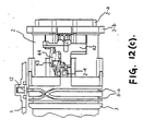
- the type drum 3 Just before the type drum 3 completes one rotation, the type drum 3 enters the process which shifts it down from the upper place columns toward the lower place columns. As the type drum 3 rotates, the engagement of the cam grooves 3-a and the rotor 12 move the type drum 3 one column toward the lower place columns. At this time, one of the four keys 3-c of the type drum 3 pushes against the cam surface 43-a of the retention claw 43 and turns the retention claw 43 in the direction of the arrow in Figure 12 (b), and at the same time, the slide teeth 42 are pushed so that they slide toward the lower place columns. In this state, the teeth (approximately two) of the slide teeth 42 are positioned where they can mesh with the gear 35-c of the drum drive gear 35 in the column direction ( Figure 12 (b)).
- the type selection and printing process described above is repeated. This time, the print colour corresponding to the column position replaces that in the first rotation of the type drum 3. Therefore, columns can be printed which could not be printed in the desired print colour in the first rotation.
- the type drum 3 Just before the type drum 3 completes its second rotation, the type drum 3 enters the process which shifts it toward the upper place columns.
- the engagement of the cam groove 3-a and the rotor 12 moves the type drum 3 one column toward the upper place columns.
- the stop 43-b of the retention claw 43 rides over the stop 42-b of the slide teeth 42, so that the slide teeth 42 are no longer stopped by the retention claw 43.
- the slide teeth 42 are moved toward the upper place columns by the spring force of the slide spring 44 together with the shifting of the type drum 3 and stop against the projection 2-e of the drum gear 2.
- the teeth (approximately 2) of the slide teeth 42 are at a position where they cannot mesh with the gear 35-c of the drum drive gear 35 in the circumferential direction ( Figure 12 (c)).
- the paper feed process begins.
- the type drum 3 is positioned toward the upper place columns as shown in Figure 14, and the positional relationship of the paper feed drive gear 3-d of the type drum 3 and the paper feed gear 23 allows them to mesh.
- the paper feed drive gear 3-d and the paper feed gear 23 mesh, and the paper feed gear 23 rotates the prescribed amount to feed the paper one line.
- the slide teeth 42 are at a position where they cannot mesh with the gear 35-c of the drum drive gear 35 in the column direction, but they are at a position where they can stop against the stopper 1-c of the frame 1.
- the gear 2-b of the drum gear 2 is at a position opposite the drum drive gear 35 where the teeth are notched, so that the transfer of power from the drum drive gear 35 to the drum gear 2 is cut off. Therefore, the drum gear 2 stops.
- the drum gear 2 and the type drum 3 remain in an automatically stopped state until the trigger coil 46 is powered to begin rotation. This state is equivalent to the state after the initialization described above.
- the print electromagnet 5-8 and the hammers 9 are housed in the type drum 3 and the type 4a are pushed from inside the type drum 3 but this invention may also be applied to printers in which the type are pushed from outside the drum and to impact printers.
- this invention is not limited to printers in which the print electromagnet 5-8 and hammers 9 are housed inside the type drum 3, but it may also be applied to printers in which the type are pushed from outside the type drum.
- a DC motor was used as the drive source, but an AC motor may also be used.
- a flat spring was used as the damper spring 54, but a coil spring may also be used.
- a type drum to which at least two colours are alternately applied in the column direction is alternately shifted in the column direction each rotation, and when the type drum has rotated twice, it is automatically stopped in its initial phase.
- the selection and stop release mechanism rotates the type drum and selects the type, and it also releases the automatically stopped condition of the type drum at the start of printing a line.
- the selection mechanism is controlled by powering the trigger mechanism in synchronisation with the pulse corresponding to the type position on the type drum and generated by the timing pulse detection mechanism. This series of operations is performed using the power from an efficient, compact DC motor as a drive source.
- the timing pulse is also generated from the detection mechanism during type selection, so that the hammer drive in the printing process; i.e. the powering of the print electromagnet, can be performed in synchronisation with the timing pulse. Further, this timing pulse can also be used during rotation of the type drum to count the type position and determine the drive timing of the selection mechanism.
- type printers can be driven by an extremely simple control method and a low cost drive circuit, and since low cost control circuits and software can be used, calculators and cash registers can be offered at low cost and the time required for development of the control circuit reduced.
- vibration or rotational fluctuation generated in the type drum 3 is suppressed, and degradation of print quality due to vibration during printing or incorrect selection in the next selection due to rotational fluctuation immediately after the type drum 3 has been driven is prevented, thus raising the speed and reliability of the type printer.
- the space inside the type drum 3 or inside the drum gear 2 which makes up part of the selection mechanism is used to house the motor 11 (DC motor), so that the printer can be made more compact. Further, one end of the yoke 5 of the print electromagnet can be passed through the space between the inside of the type drum 3 or the drum gear 2 and the outside of the motor 11, and the print electromagnet inside the type drum can be secured to the printer body. Another advantage is that rotational noise generated by the motor is shielded, thus greatly reducing the operating noise of the printer.
Landscapes
- Common Mechanisms (AREA)
Applications Claiming Priority (8)
| Application Number | Priority Date | Filing Date | Title |
|---|---|---|---|
| JP21158789A JPH0375169A (ja) | 1989-08-17 | 1989-08-17 | 活字式プリンタ |
| JP211587/89 | 1989-08-17 | ||
| JP211588/89 | 1989-08-17 | ||
| JP21158889A JPH0375170A (ja) | 1989-08-17 | 1989-08-17 | 活字式プリンタ |
| JP21158689A JPH0375177A (ja) | 1989-08-17 | 1989-08-17 | 活字ドラム式プリンタ |
| JP1211585A JPH0813544B2 (ja) | 1989-08-17 | 1989-08-17 | 活字ドラム式プリンタ |
| JP211585/89 | 1989-08-17 | ||
| JP211586/89 | 1989-08-17 |
Publications (2)
| Publication Number | Publication Date |
|---|---|
| EP0413575A2 true EP0413575A2 (fr) | 1991-02-20 |
| EP0413575A3 EP0413575A3 (en) | 1991-10-23 |
Family
ID=27476555
Family Applications (1)
| Application Number | Title | Priority Date | Filing Date |
|---|---|---|---|
| EP19900308978 Withdrawn EP0413575A3 (en) | 1989-08-17 | 1990-08-15 | Type printer |
Country Status (2)
| Country | Link |
|---|---|
| US (1) | US5221149A (fr) |
| EP (1) | EP0413575A3 (fr) |
Families Citing this family (2)
| Publication number | Priority date | Publication date | Assignee | Title |
|---|---|---|---|---|
| US5813783A (en) * | 1996-06-24 | 1998-09-29 | Fuji Photo Film Co., Ltd. | Conveying device for a recording paper |
| US10625523B2 (en) | 2016-05-27 | 2020-04-21 | Hewlett-Packard Development Company, L.P. | Braking system |
Family Cites Families (9)
| Publication number | Priority date | Publication date | Assignee | Title |
|---|---|---|---|---|
| BE636591A (fr) * | 1962-09-10 | |||
| DK127277C (fr) * | 1972-03-06 | |||
| US3890894A (en) * | 1972-05-04 | 1975-06-24 | Citizen Watch Co Ltd | Electromagnetically-operated printer |
| GB1591188A (en) * | 1976-08-27 | 1981-06-17 | Shinshu Seiki Kk | Printer |
| JPS57181883A (en) * | 1981-05-06 | 1982-11-09 | Canon Electronics Inc | Compact printer |
| DE3441069A1 (de) * | 1983-11-10 | 1985-05-23 | EPSON Corp., Shinjuku, Tokio/Tokyo | Seriendrucker |
| US4723855A (en) * | 1985-01-17 | 1988-02-09 | Seiko Epson Corp. | Compact printer |
| US4741268A (en) * | 1985-12-20 | 1988-05-03 | Alps Electric Co., Ltd. | Planetary transmission system for selective type wheels |
| IT1206877B (it) * | 1987-01-30 | 1989-05-11 | Olivetti & Co Spa | Stampante seriale bicolore |
-
1990
- 1990-08-14 US US07/566,915 patent/US5221149A/en not_active Expired - Fee Related
- 1990-08-15 EP EP19900308978 patent/EP0413575A3/en not_active Withdrawn
Also Published As
| Publication number | Publication date |
|---|---|
| EP0413575A3 (en) | 1991-10-23 |
| US5221149A (en) | 1993-06-22 |
Similar Documents
| Publication | Publication Date | Title |
|---|---|---|
| EP0413575A2 (fr) | Imprimante pour caractères | |
| GB2056918A (en) | Serial printer | |
| US4551033A (en) | Serial electric printer using single unidirectional motor | |
| US4244290A (en) | Miniature printer | |
| JPH025586B2 (fr) | ||
| JPH0375169A (ja) | 活字式プリンタ | |
| JPH0813544B2 (ja) | 活字ドラム式プリンタ | |
| US4632581A (en) | Serial printer having trigger mechanism | |
| KR900002486B1 (ko) | 동력전달장치 | |
| GB2078619A (en) | Serial printer | |
| JPH0375170A (ja) | 活字式プリンタ | |
| JPH04131262A (ja) | 活字式プリンタ | |
| EP0065836A2 (fr) | Mécanisme d'impression, p.e. pour calculatrice de poche | |
| JPH0375177A (ja) | 活字ドラム式プリンタ | |
| JPH0516321U (ja) | 活字式ドラムプリンタ | |
| JPH0113435B2 (fr) | ||
| GB2095181A (en) | Character selection in type wheel printer | |
| US5033886A (en) | Printer | |
| US5152616A (en) | Miniature printer | |
| US4420267A (en) | Serial printer | |
| JPS6358097B2 (fr) | ||
| KR920005761B1 (ko) | 마이크로프린터 | |
| GB2057974A (en) | Printer | |
| JPH0326147B2 (fr) | ||
| JPH0243738Y2 (fr) |
Legal Events
| Date | Code | Title | Description |
|---|---|---|---|
| PUAI | Public reference made under article 153(3) epc to a published international application that has entered the european phase |
Free format text: ORIGINAL CODE: 0009012 |
|
| AK | Designated contracting states |
Kind code of ref document: A2 Designated state(s): DE FR GB |
|
| PUAL | Search report despatched |
Free format text: ORIGINAL CODE: 0009013 |
|
| AK | Designated contracting states |
Kind code of ref document: A3 Designated state(s): DE FR GB |
|
| STAA | Information on the status of an ep patent application or granted ep patent |
Free format text: STATUS: THE APPLICATION IS DEEMED TO BE WITHDRAWN |
|
| 18D | Application deemed to be withdrawn |
Effective date: 19920424 |