EP0413601A1 - Appareil totalisateur pour des dispositifs de mesure de débit - Google Patents
Appareil totalisateur pour des dispositifs de mesure de débit Download PDFInfo
- Publication number
- EP0413601A1 EP0413601A1 EP90309058A EP90309058A EP0413601A1 EP 0413601 A1 EP0413601 A1 EP 0413601A1 EP 90309058 A EP90309058 A EP 90309058A EP 90309058 A EP90309058 A EP 90309058A EP 0413601 A1 EP0413601 A1 EP 0413601A1
- Authority
- EP
- European Patent Office
- Prior art keywords
- totalizer
- zero
- belt
- during
- zeroing operation
- Prior art date
- Legal status (The legal status is an assumption and is not a legal conclusion. Google has not performed a legal analysis and makes no representation as to the accuracy of the status listed.)
- Granted
Links
Images




Classifications
-
- G—PHYSICS
- G01—MEASURING; TESTING
- G01G—WEIGHING
- G01G11/00—Apparatus for weighing a continuous stream of material during flow; Conveyor belt weighers
- G01G11/14—Apparatus for weighing a continuous stream of material during flow; Conveyor belt weighers using totalising or integrating devices
- G01G11/16—Apparatus for weighing a continuous stream of material during flow; Conveyor belt weighers using totalising or integrating devices being electrical or electronic means
- G01G11/18—Apparatus for weighing a continuous stream of material during flow; Conveyor belt weighers using totalising or integrating devices being electrical or electronic means using digital counting
-
- G—PHYSICS
- G01—MEASURING; TESTING
- G01G—WEIGHING
- G01G11/00—Apparatus for weighing a continuous stream of material during flow; Conveyor belt weighers
- G01G11/006—Special taring or checking devices therefor
-
- G—PHYSICS
- G01—MEASURING; TESTING
- G01G—WEIGHING
- G01G11/00—Apparatus for weighing a continuous stream of material during flow; Conveyor belt weighers
- G01G11/04—Apparatus for weighing a continuous stream of material during flow; Conveyor belt weighers having electrical weight-sensitive devices
- G01G11/043—Apparatus for weighing a continuous stream of material during flow; Conveyor belt weighers having electrical weight-sensitive devices combined with totalising or integrating devices
-
- G—PHYSICS
- G01—MEASURING; TESTING
- G01G—WEIGHING
- G01G23/00—Auxiliary devices for weighing apparatus
- G01G23/14—Devices for determining tare weight or for cancelling out the tare by zeroising, e.g. mechanically operated
- G01G23/16—Devices for determining tare weight or for cancelling out the tare by zeroising, e.g. mechanically operated electrically or magnetically operated
- G01G23/163—Devices for determining tare weight or for cancelling out the tare by zeroising, e.g. mechanically operated electrically or magnetically operated involving digital counting
Definitions
- This invention relates to totalizer units for belt scales, flowmeters and other devices for measuring the bulk, mass or weight of material flowing or being conveyed past a fixed point at which the instantaneous loading on a suitable transducer or transducers is continuously sensed.
- a transducer or group of transducers is arranged to generate an electrical signal proportional to the instantaneous loading applied to an element which reacts to the flow of material, and this signal is multiplied by the speed of flow and integrated in order to produce an output corresponding to the quantity of material which has passed the element.
- the apparatus may be arranged so that the speed of flow is constant, whilst in belt scales the speed of the belt is measured by a suitable sensor such as a pulse generating tachometer.
- the zero load output of the transducer may shift for example due to changes in transducer characteristics, because of material adhering to the conveyor belt in a belt scale or the sensor plate in a flowmeter, because of wear of the belt in a belt scale, or because of temperature or humidity variations. Any such zeroing in a belt scale must allow for the tare of the belt, which varies not only as the belt wears, but from point to point on the belt itself.
- the belt will usually be heavier in the immediate vicinity of a splice in the belt as well as having other irregularities. For this reason, zeroing of control and display units for belt scales is usually performed by monitoring output over one or more full revolutions of the belt through the system so as to find a setting which will produce an overall integrated output which is zero.
- Belt scale systems are also usually set up so that outputs corresponding to very low rates of flow, below a certain threshold, are disregarded. Any such threshold setting must be disabled prior to zeroing, since otherwise it will act so as to shift the zero setting.
- An autozeroing operation must also be scheduled so as not to interfere with normal operation of the apparatus when a load is present. Unfortunately, it is not possible for the apparatus to predict when a gap in the flow of material will occur which is long enough for the autozeroing function to be completed. If flow recommences whilst the zeroing function is in progress, both the function itself will be aborted, and material will pass through the system without being weighed. If a substantial lump of material temporarily sticks on a belt or flowmeter element, it may produce a temporary false zero which will cease to be valid as soon as the lump shifts.
- An object of the present invention is to provide a control and display unit for belt scales, and other devices for measuring rates of flow, which addresses the above problems.
- apparatus for integrating a flow proportional signal, from a flow rate measuring device subject to zero drift, while the flow proportional signal, after application of a zero correction determined by a zeroing operation, exceeds a first predetermined threshold comprising: means applying a zero correction to said flow proportional signal; a first totalizer for accumulating the time integral of said zero corrected flow proportional signal while the threshold is exceeded; and means operative to redetermine a zero correction during a zeroing operation; wherein said zero correction redetermining means further comprises: means disabling said first totalizer during said zeroing operation; a second totalizer operative to accumulate a time integral of said zero corrected flow proportional signal during said zeroing operation; threshold means to reject said redetermined zero correction determined during a zeroing operation if it deviates excessively from a reference; and means responsive to rejection of said redetermined zero correction by said threshold means to add the integral accumulated in said second totalizer during the zeroing operation to that accumulated in said first totalizer.
- a second totalizer means that no totalizer error should occur if flow restarts during a zeroing operation, since the result of the zeroing operation will be rejected and the count of the second totalizer will compensate for counts lost by the first totalizer.
- the apparatus preferably includes a third totalizer operative to accumulate the time integral of the flow proportional signal, first timer means associated with the third totalizer, means to reset the third totalizer and the first timer means upon either the third totalizer accumulating a predetermined total or the first timer means timing a predetermined elapsed time interval, and means, responsive to the first timer means timing said predetermined elapsed time interval before the total accumulated by the third totalizer reaches a second predetermined threshold, to initiate said zeroing operation. This will ensure that a zeroing operation is only initiated when there has been no flow for a sufficient interval that it is likely that the operation can be completed without flow recommencing.
- the apparatus comprises a register operative during a zeroing operation to accumulate samples of said flow proportional signal prior to zero correction, a second register to accumulate a count of said samples, second timer means to terminate the zeroing operation after a predetermined elapsed time interval, and means to calculate a zero correction from the average value of said samples.
- the flow rate measuring device is typically a belt conveyor weigh scale, but the apparatus may also be used with other types of flowmeters.
- the timebase of the timers is based on an integral number of belt revolutions so as to cancel the effect of light and heavy sections of the belt.
- Figure 1 shows the general layout of apparatus according to the invention as applied to a belt scale.
- a conveyor 2 has a belt 4 which receives material at a point 6 and discharges it at a point 8. Between points 6 and 8 the belt passes across a belt scale unit 10 which contains one or more load cells which provide a signal continuously proportional to the load on a portion of the belt supported by means coupled to the load cells.
- a suitable form of belt scale unit is described in U.S. Patent No. 4,682,664 issued July 28, 1987, to Charles W. Kemp, although use of the present invention does not require use of any particular belt scale unit provided that is capable of providing an output signal proportional to load. Whilst the apparatus will be described as applied to a belt scale, it may also be employed with a flowmeter, in which case various functions associated with belt speed are omitted or substituted as discussed further below.
- the signal from the unit 10 is applied through an interface 12 and a voltage-to-frequency converter 14 to a micro-controller 16, which in the example described was a 68HC11 micro-controller from Motorola, although other micro-controllers, or microprocessors with suitable peripherals functions could of course be utilized.
- a pulse signal from a tachometer 18 driven by the belt is also applied through an interface 20 to the micro-controller 16.
- the micro-controller is provided with memory comprising read only memory (ROM) 22 utilized to store an operating program and certain fixed data, nonvolatile memory (EEPROM) 24 utilized to retain data when the apparatus is powered down, particularly operator selectable parameters and cumulative data, and random access memory (RAM) 26 used to provide working memory and temporary storage of data during normal operation of the apparatus.
- the micro-controller receives further inputs from an operator through a keyboard 28 connected through an interface 30, and push buttons 32 connected through an interface 34. It typically provides outputs to an alphanumeric display 36 through a suitable interface 38, an analog rate meter 40 through a digital-to-analog converter 42, and a remote totalizer 44 through a pulsing device 46.
- the micro-controller is provided with a real time clock 48 generating real time interrupts at fixed intervals. According to the micro-controller used, this real time clock may be internally implemented in the micro-controller unit.
- the micro-controller on power-up enters a main program which first calls a routine INITIALIZE. This recovers data stored in EEPROM 24, so as to restore the status of the apparatus to that existing immediately prior to power-down by transferring stored parameters to predetermined locations in RAM 26, initializing certain registers, and also setting both an internally implemented totalizer, whose count is normally displayed by display 36, and the totalizer 44 to an accumulated count reached prior to power-down. It also initializes the display 36. The program then enters an executive control program loop (ECPL) as shown in Figure 2, which program loop in turn executes in turn a number of subprograms.
- ECPL executive control program loop
- the subprograms are designed so that their processing does not require more than a fairly minimal time even under worst-case conditions, and so that the entire ECPL can be executed repeatedly at a reasonable rate, typically about eight times per second. Whilst each subprogram will be entered upon each execution of the loop, what is done upon each such entry depends on the setting of operational parameters, the settings of flags by previous operations, and operator input using the keyboard or push buttons. As will be seen, subprograms may carry out quite different tasks depending upon these settings.
- Overflow of the register generates an interrupt (step 703) which triggers an interrupt service routine ISR4, which increments an overflow counter (step 704) and returns.
- Real time interrupts generated (step 705) by real time clock 48 trigger an interrupt service routine ISR14 which combines and stores (step 708), as a variable ADCOUNT, the pulse accumulator count and the overflow count from the accumulator count and overflow registers, resets these registers and returns from the interrupt.
- the real time interrupts may be counted in a step 706, and only every fourth (or some other appropriate number) interrupt (step 707) acts to store the count ADCOUNT and reset the registers.
- Each pulse generated (step 600) by the tachometer 18 initiates an interrupt service routine ISR15 (see Figure 6) which first determines at step 601 whether or not a new speed determination cycle is commencing, as indicated by a speed register SPDCNT being set to zero. If it is, the count of a free running counter clocked by high frequency clock pulses (step 606) is transferred to a register COUNT1 (step 602) and the speed register is reset (step 603). Whether or not the speed counter is set to zero, the count from the free running counter is also transferred to a register COUNTM (step 604) and the speed register SPDCNT is incremented (step 605).
- the free running counter includes a primary counter TCNT, and an overflow counter MCNT. Overflow (step 607) of the counter TCNT initiates an interrupt service routine ISR5 which increments overflow counter MCNT (step 608) and then returns.
- the subprograms called by the executive control program loop (ECPL) shown in Figure 2 will now be considered.
- the subprogram 200 entitled TOTAL, calculates the rate of material flow along the belt (or through the flowmeter as the case may be), primarily from the contents of ADCOUNT register, and also increments the local totalizer register implemented by the microcontroller 16, and the remote totalizer 44.
- the subprogram also increments a supplementary autozeroing totalizer register AZ as discussed further below.
- the calculated rates used to increment the totalizer registers are adjusted by a zero correction corresponding to an unloaded or no flow condition of the belt or flowmeter, and damping is applied to prevent excessive short term fluctuation of the calculated rate.
- a mode test 201 either executes or bypasses a program 202 (SPEED) which calculates the speed of the belt of a belt scale from the counts stored in registers COUNT1, COUNTM and SPDCNT by subtracting the content of register COUNT1 from that of COUNTM, dividing the result by SPDCNT, and scaling and damping the result appropriately.
- SPEED program 202
- the next subprogram 203 to be called handles any key value stored as input from the keyboard and exits if no key value has been stored. If a key value has been stored it is transferred to an input buffer, and an appropriate action initiated according to the identity and the existing content of the buffer. Where the content of buffer constitutes a complete command to the system the command is executed if execution is possible, if necessary in multiple stages on successive executions of the ECPL, within the time constraints imposed by the necessity of completing the loop fast enough to allow for a desired repetition rate.
- An ANALOG OUTPUT subprogram 204 is called next, which checks whether analog output is required, and performs a step in an analog output procedure if such output is required.
- the next subprogram 205 to be entered is a ZERO program, which carries out certain functions involved in a zeroing operation and is described in more detail below.
- This zeroing operation may be either a zeroing operation which is manually initiated, in which case a flag will be set to initiate the zeroing operation, or an autozeroing operation, in which case the subprogram will either reset or increment a timing register and check whether the register count has reached a calculated level such that an autozeroing operation is due, so that on the following execution of subprogram 205, the zeroing operation can be initiated.
- Subprogram 206 carries out a conventional span operation if the keyboard action program has responded to keyboard input to set flags indicating that a span operation is required.
- Subprogram 207 DYNAMIC DISPLAY
- Subprogram 208 reads the push buttons 32. These buttons in general provide inputs equivalent to those provided by the keyboard, and equivalent inputs are handled similarly to those from the keyboard, handled by the keyboard input subprogram 210.
- Subprogram 209, METER enables the output of the load cells or other sensors to be monitored directly, using the analog to digital converter 42 controlled by micro-controller 16.
- a KEYBOARD INPUT subprogram 210 provides a keyboard input routine which senses whether a key on the keyboard 28 has been depressed, and stores the value of any depressed key for subsequent processing by the keyboard action program.
- the ECPL loop just described is continuously repeated during normal operation of the unit, the subprograms being constructed as already mentioned so that the execution time of the loop remains fairly constant (typically about 8 times a second). Some tasks carried out by certain of the subprograms such as a zeroing or spanning operation which requires continuous monitoring of the operation of the belt scale or flowmeter over a substantial period must be carried out in stages over many repetitions of the loop.
- Zeroing operations may be of several different types, initiated in different ways. When the apparatus is first powered up, an initial zeroing operation is required. A zeroing operation may be initiated manually either from the keyboard 28 or by a designated one of the push buttons 32. Finally, a zeroing operation may be initiated automatically if certain conditions are fulfilled.
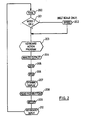
- An initial zeroing operation is manually initiated after the apparatus is powered up for the first time, or at any time provided that the operator first sets an appropriate parameter requiring either complete reinitiatization of the unit or zero reinitialization only. Detection of any of these conditions results in a flag IZFLG being set. The setting of this flag disables testing for whether the zero setting determined deviates excessively from that already existing. Otherwise the process is as described below, with reference to Figure 3.
- the KEYBOARD INPUT program 210 reads the keyboard and stores a 'Z' in a variable KEY. If a zeroing operation is initiated manually by push button, the READ PUSH BUTTONS program does the same thing provided that a zeroing operation is not already in progress. A flag ZPBTFLG indicating that a push button zeroing operation has been requested is also set in this case. The keyboard action program 203 then reacts to the 'Z' in KEY by clearing various flags and registers and setting a flag ZEROFLG (step 301) to indicate that a zeroing operation has been requested.
- step 302 If the flag ZPBFLG is found set (step 302) it also stores an 'E' as the variable KEY in place of the 'Z' (step 303). Otherwise, the ECPL continues until the KEYBOARD INPUT program determines (step 304) that the enter key has been pressed to initiate the zeroing operation, in which case it stores an 'E' in the variable KEY.
- EXECUTE subprogram Upon the next execution of the KEYBOARD ACTION program, the presence of the 'E' in variable KEY is detected, and after determining that it does not represent the end of a parameter entry, an EXECUTE subprogram is called, the operations carried out by this program depending on the flag settings which it finds.
- the EXECUTE subprogram first calls a routine RES-CTRS (step 305) which resets various registers to suit a zeroing or spanning operation including a register RUNTIME, calculates from available data the time for one belt revolution, which it places in a register REVTIME, and then tests the flag ZEROFLG. If found set, it is reset, and a flag ZPFLG is set to indicate that a zeroing operation is under way, at which point control is returned to the ECPL.
- the ZERO program When the ZERO program is entered, it detects that the zero in progress flag ZPFLG is sets and sets (step 306) a zero wait flag ZWFLG, and a calibration flag CALFLG, which cause the TOTAL program to increment RUNTIME, and weight and point count registers for each ECPL during the zeroing operation.
- the 'E' in a variable KEY is again detected, but the reset condition of flag ZEROFLG results in no action being taken, while the set condition of the flag ZPFLG results in a timer implemented by the zero program 205 testing (step 307) whether the value in register RUNTIME equals or exceeds that in a register REVTIME, i.e. whether the zeroing operation has been in progress for a full revolution of the belt.
- the RUNTIME register is updated (step 308) during each execution of the TOTAL program 200 according to the number of real time interrupts which have occurred during the ECPL.
- the total program also notes that the CALFLG is set, and updates a temporary totalizer register TOTCAL in place of the regular totalizer register (step 317).
- the program continues to loop through the ECPL until such a time as the content of the RUNTIME register equals or exceeds that of the REVTIME register.
- the zero program calculates (step 309) a temporary zero count ZEROCTX from the WEIGHT_CT and POINT_CT data accumulated by the TOTAL program whilst the zeroing operation was in progress.
- the zero in progress and zero wait flags ZPFLG and ZWFLG are reset, and a zero deviation flag ZDEVFLG is set before execution returns to the ECPL.
- the keyboard action program again detects the 'E' entry in register KEY, resulting in calling of the EXECUTE subprogram which detects the set condition of the ZDEVFLG and sets the flag ZEROFLG. If the initial zero flag IZFLG was set (step 310), the temporary zero count accumulated during the zeroing operation is adopted (step 311) and stored both as an initial zero count EOZERO and as an existing zero count EZEROCNT, and the ZDEVFLG, ISFLG and ZEROFLG flags are reset. If the initial zero flag is not set, then the difference between the temporary zero count ZEROCTX and EOZERO is expressed (step 312) as a percentage of EOZERO.
- This percentage representing the percentage deviation ZDEV of the zero from its initial value, is then compared (step 313) with a threshold, typically 12%, to determine whether the result of the zeroing operation should be rejected as erroneous since it represents an excessive deviation, probably due to material passing on the belt during the zeroing operation.
- a threshold typically 12%
- the content of the calibration totalizer TOTCAL is added to the regular totalizer (step 314) and the existing zero setting is retained (step 315). If the deviation is less than 12%, the temporary zero count is stored (step 316) as the actual zero count EZEROCNT, and the ZDEVFLG and ZEROFLG flags are reset, thus terminating the zeroing operation.
- a flag ZFLG is cleared.
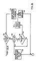
- AZCNT0 represents the number of cycles through the ECPL for which suitable autozeroing conditions must persist before an autozeroing operation is initiated.
- a calculation (step 401) is made of the number ax of ECPL loops required for the totalizer to be incremented by a single count when the belt is carrying a very small portion, typically 1%, of its rated load rate.
- TOTC represents the weight of material resulting in one totalizer count
- a comparison (402) is then made between bx and ax, and if bx is less than ax, bx is added to itself (step 403), and the comparison repeated until bx is no longer less than ax, at which point bx is stored as AZCNT0 (step 404).
- the flag ZFLG is set (step 411), so that the above calculations are not repeated unnecessarily (see step 405).
- the TOTAL program 200 When the TOTAL program 200 is executed upon each pass through the ECPL, it not only performs calculations to determine whether alteration is required to the main and remote totalizer readings, but also maintains a further totalizer register AZ.
- the total weight count accumulated during an ECPL is divided by the number of real time interrupts occurring since the last execution of the TOTAL program to provide an average count ADCNT2 per real time interrupt, this count being adjusted by the zero count ZEROCNT to allow for the existing zero setting and provide an adjusted count CCC.
- the adjusted count is then multiplied by the belt speed SPEED_C determined by the speed program, and an appropriate constant KO2 to obtain a rate figure RATE.
- the separate totalizer register AZ is also maintained, which receives the uncorrected RATE data, RATE being repeatedly added to AZ for each real time interrupt during the preceding ECPL. If the absolute value of the content of AZ, whether positive or negative, is found to exceed (step 406) a value AZMAX, calculated as the equivalent of a predefined number, typically 2, of totalizer counts by which the totalizer may vary from its starting figure, it is assumed that conditions are unsuitable for an autozeroing operation, and a register AZCNT, discussed further below, is reset to zero (step 407).
- Figure 5 illustrates how AZ may vary during a belt revolution relative to AZMAX.
- the zero program 205 Upon each pass through the ECPL, the zero program 205, having established that the apparatus is running normally and that the belt speed is at least one tenth (typically) of its maximum, increments (step 408) the register AZCNT and compares it with AZCNT0 (step 409). Each time AZ exceeds the absolute value of AZMAX, the totalizer program 200 will reset AZCNT (step 407) and the count will recommence. When AZCNT exceeds AZCNT0 (step 409), the autozero sequence is initiated (step 410) by setting variable KEY to 'Z', inserting a 'Z' and setting an autozero flag AZFLG and the zero push button flag ZPBFLG.
- step 318 Thereafter operation is similar to a zeroing operation initiated by the zero push button and already described above, apart from differences signalled by testing the autozero flag (step 318). The most significant of these differences resides in the assessment of the zero deviation AA obtained after the zero deviation flag ZDEVFLG is set. If the deviation AA is over 12% (for example) the total in TOTAL recorded during the operation is added to the totalizer, no zero correction is applied, and the operation is aborted, it being assumed that material has commenced to pass on the belt during the zeroing operation. If the deviation is less than 12%, but more than 4% (step 319) from the initial value an error message is generated (step 320) and the existing zero is retained. Only if the deviation is less than 4% from the initial value is a zero correction applied; this avoids dubious corrections being applied without operator supervision.
- the autozeroing operation proceeds similarly, but the period during which readiness for an autozeroing operation is tested, and the period over which it takes place, have to be calculated without reference to belt length or speed, and will normally have a fixed relationship to the present operating parameters of the apparatus.
Landscapes
- Physics & Mathematics (AREA)
- General Physics & Mathematics (AREA)
- Measuring Volume Flow (AREA)
- Control Of Conveyors (AREA)
- Details Of Flowmeters (AREA)
- Feedback Control In General (AREA)
Priority Applications (1)
| Application Number | Priority Date | Filing Date | Title |
|---|---|---|---|
| AT90309058T ATE83557T1 (de) | 1989-08-18 | 1990-08-17 | Totalisatorgeraet fuer durchflussmessvorrichtungen. |
Applications Claiming Priority (2)
| Application Number | Priority Date | Filing Date | Title |
|---|---|---|---|
| US07/395,517 US5003489A (en) | 1989-08-18 | 1989-08-18 | Totalizer apparatus for flow rate measurement devices |
| US395517 | 1989-08-18 |
Publications (2)
| Publication Number | Publication Date |
|---|---|
| EP0413601A1 true EP0413601A1 (fr) | 1991-02-20 |
| EP0413601B1 EP0413601B1 (fr) | 1992-12-16 |
Family
ID=23563381
Family Applications (1)
| Application Number | Title | Priority Date | Filing Date |
|---|---|---|---|
| EP90309058A Expired - Lifetime EP0413601B1 (fr) | 1989-08-18 | 1990-08-17 | Appareil totalisateur pour des dispositifs de mesure de débit |
Country Status (9)
| Country | Link |
|---|---|
| US (1) | US5003489A (fr) |
| EP (1) | EP0413601B1 (fr) |
| JP (1) | JP2868865B2 (fr) |
| AT (1) | ATE83557T1 (fr) |
| AU (1) | AU621769B2 (fr) |
| CA (1) | CA2022724C (fr) |
| DE (1) | DE69000597T2 (fr) |
| ES (1) | ES2037526T3 (fr) |
| ZA (1) | ZA906465B (fr) |
Cited By (1)
| Publication number | Priority date | Publication date | Assignee | Title |
|---|---|---|---|---|
| WO1998031993A1 (fr) * | 1997-01-17 | 1998-07-23 | K-Tron Technologies, Inc. | Balance a courroie |
Families Citing this family (4)
| Publication number | Priority date | Publication date | Assignee | Title |
|---|---|---|---|---|
| US5228327A (en) * | 1991-07-11 | 1993-07-20 | Micro Motion, Inc. | Technique for determining a mechanical zero value for a coriolis meter |
| US5497664A (en) * | 1994-11-14 | 1996-03-12 | Jorritsma; Johannes N. | Method and apparatus for calculating flow rates through a pumping station |
| US5894273A (en) * | 1996-08-26 | 1999-04-13 | Fairway Medical Technologies, Inc. | Centrifugal blood pump driver apparatus |
| CN114719945B (zh) * | 2022-04-01 | 2023-07-21 | 广东中烟工业有限责任公司 | 控制性电子皮带秤流量控制精度自适应方法、系统和计算机介质 |
Citations (2)
| Publication number | Priority date | Publication date | Assignee | Title |
|---|---|---|---|---|
| US3559451A (en) * | 1969-12-22 | 1971-02-02 | Cutler Hammer Inc | Weighing scale system for a conveyor with footage counter for improved calibration |
| US3960225A (en) * | 1973-11-21 | 1976-06-01 | Hyer Industries, Inc. | Conveyor belt system with positional transformation of weight data |
Family Cites Families (6)
| Publication number | Priority date | Publication date | Assignee | Title |
|---|---|---|---|---|
| US4882781A (en) * | 1981-09-09 | 1989-11-21 | Isco, Inc. | Method for predicting steady-state conditions |
| JPS58223021A (ja) * | 1982-06-21 | 1983-12-24 | Oval Eng Co Ltd | 器差調整回路 |
| US4682644A (en) * | 1982-12-06 | 1987-07-28 | Kyocera Kabushiki Kaisha | Mold for use in dental precision casting |
| US4593365A (en) * | 1983-04-06 | 1986-06-03 | Halliburton Company | Apparatus and method for monitoring a plurality of flow meters |
| US4829449A (en) * | 1986-02-05 | 1989-05-09 | Rockwell International Corporation | Method and apparatus for measuring and providing corrected gas flow |
| US4700568A (en) * | 1986-03-11 | 1987-10-20 | Kerr-Mcgee Corporation | Pulse accumulator network adapted for use in a flow monitoring system |
-
1989
- 1989-08-18 US US07/395,517 patent/US5003489A/en not_active Expired - Lifetime
-
1990
- 1990-08-03 CA CA002022724A patent/CA2022724C/fr not_active Expired - Fee Related
- 1990-08-06 AU AU60192/90A patent/AU621769B2/en not_active Ceased
- 1990-08-15 JP JP2214474A patent/JP2868865B2/ja not_active Expired - Lifetime
- 1990-08-15 ZA ZA906465A patent/ZA906465B/xx unknown
- 1990-08-17 ES ES199090309058T patent/ES2037526T3/es not_active Expired - Lifetime
- 1990-08-17 AT AT90309058T patent/ATE83557T1/de not_active IP Right Cessation
- 1990-08-17 EP EP90309058A patent/EP0413601B1/fr not_active Expired - Lifetime
- 1990-08-17 DE DE9090309058T patent/DE69000597T2/de not_active Expired - Fee Related
Patent Citations (2)
| Publication number | Priority date | Publication date | Assignee | Title |
|---|---|---|---|---|
| US3559451A (en) * | 1969-12-22 | 1971-02-02 | Cutler Hammer Inc | Weighing scale system for a conveyor with footage counter for improved calibration |
| US3960225A (en) * | 1973-11-21 | 1976-06-01 | Hyer Industries, Inc. | Conveyor belt system with positional transformation of weight data |
Non-Patent Citations (1)
| Title |
|---|
| PATENT ABSTRACTS OF JAPAN, vol. 6, no. 96 (P-120)[974], 4th June 1982; & JP-A-57 30 912 (YAMATO SEIKOV K.K.) 19-02-1982 * |
Cited By (2)
| Publication number | Priority date | Publication date | Assignee | Title |
|---|---|---|---|---|
| WO1998031993A1 (fr) * | 1997-01-17 | 1998-07-23 | K-Tron Technologies, Inc. | Balance a courroie |
| US6437255B1 (en) | 1997-01-17 | 2002-08-20 | K-Tron Technologies, Inc. | Conveyor scale |
Also Published As
| Publication number | Publication date |
|---|---|
| JPH03170030A (ja) | 1991-07-23 |
| AU6019290A (en) | 1991-02-21 |
| DE69000597D1 (de) | 1993-01-28 |
| ZA906465B (en) | 1991-07-31 |
| EP0413601B1 (fr) | 1992-12-16 |
| CA2022724C (fr) | 1994-10-18 |
| ATE83557T1 (de) | 1993-01-15 |
| CA2022724A1 (fr) | 1991-02-19 |
| ES2037526T3 (es) | 1993-06-16 |
| US5003489A (en) | 1991-03-26 |
| JP2868865B2 (ja) | 1999-03-10 |
| DE69000597T2 (de) | 1993-06-24 |
| AU621769B2 (en) | 1992-03-19 |
Similar Documents
| Publication | Publication Date | Title |
|---|---|---|
| JP3117220B2 (ja) | 連続計量メータ | |
| US4534428A (en) | Vibratory feeder control for a weighing system | |
| US4709770A (en) | Device for correcting dynamic weight signal from conveyer weigher | |
| US4320855A (en) | Weigh feeding apparatus | |
| US4858161A (en) | Method for the automatic calibration of a high-resolution electronic balance | |
| USRE32102E (en) | Weigh feeding apparatus | |
| GB2239966A (en) | Controlling discharge rates of loss-in-weight feeders | |
| EP0413601B1 (fr) | Appareil totalisateur pour des dispositifs de mesure de débit | |
| JPS6148089B2 (fr) | ||
| CA1094586A (fr) | Balance pour marchandises en vrac | |
| EP0225482B1 (fr) | Système de contrôle de consommation de papier | |
| EP0393998A1 (fr) | Système de calibrage dans une balance de combinaison | |
| HK31895A (en) | Gas shutoff apparatus | |
| US4625817A (en) | Method of zero adjustment for combinatorial weighing or counting system | |
| JP4530489B2 (ja) | 定量計量装置 | |
| JPH0743196A (ja) | 組合せ秤における計量信号の安定時間チェック装置 | |
| US5379390A (en) | Rate/ratio determining apparatus | |
| JP4530490B2 (ja) | 定量計量器付巻取装置 | |
| US5051915A (en) | Frequency measuring apparatus | |
| US4955240A (en) | Vibration type force detector | |
| JPH0136095Y2 (fr) | ||
| SU1687659A1 (ru) | Устройство дл контрол производительности батареи хлопкоперерабатывающих машин | |
| SU1278598A1 (ru) | Дозатор непрерывного действи | |
| SU1569574A1 (ru) | Конвейерные весы | |
| SU879316A1 (ru) | Весовой порционный дозатор |
Legal Events
| Date | Code | Title | Description |
|---|---|---|---|
| PUAI | Public reference made under article 153(3) epc to a published international application that has entered the european phase |
Free format text: ORIGINAL CODE: 0009012 |
|
| AK | Designated contracting states |
Kind code of ref document: A1 Designated state(s): AT BE CH DE DK ES FR GB GR IT LI LU NL SE |
|
| 17P | Request for examination filed |
Effective date: 19910808 |
|
| RAP1 | Party data changed (applicant data changed or rights of an application transferred) |
Owner name: MILLTRONICS LTD. |
|
| 17Q | First examination report despatched |
Effective date: 19920330 |
|
| GRAA | (expected) grant |
Free format text: ORIGINAL CODE: 0009210 |
|
| AK | Designated contracting states |
Kind code of ref document: B1 Designated state(s): AT BE CH DE DK ES FR GB GR IT LI LU NL SE |
|
| PG25 | Lapsed in a contracting state [announced via postgrant information from national office to epo] |
Ref country code: GR Free format text: LAPSE BECAUSE OF FAILURE TO SUBMIT A TRANSLATION OF THE DESCRIPTION OR TO PAY THE FEE WITHIN THE PRESCRIBED TIME-LIMIT Effective date: 19921216 Ref country code: LI Effective date: 19921216 Ref country code: AT Effective date: 19921216 Ref country code: NL Effective date: 19921216 Ref country code: CH Effective date: 19921216 Ref country code: DK Effective date: 19921216 |
|
| REF | Corresponds to: |
Ref document number: 83557 Country of ref document: AT Date of ref document: 19930115 Kind code of ref document: T |
|
| REF | Corresponds to: |
Ref document number: 69000597 Country of ref document: DE Date of ref document: 19930128 |
|
| ITF | It: translation for a ep patent filed | ||
| ET | Fr: translation filed | ||
| REG | Reference to a national code |
Ref country code: CH Ref legal event code: PL |
|
| NLV1 | Nl: lapsed or annulled due to failure to fulfill the requirements of art. 29p and 29m of the patents act | ||
| REG | Reference to a national code |
Ref country code: ES Ref legal event code: FG2A Ref document number: 2037526 Country of ref document: ES Kind code of ref document: T3 |
|
| PG25 | Lapsed in a contracting state [announced via postgrant information from national office to epo] |
Ref country code: LU Free format text: LAPSE BECAUSE OF NON-PAYMENT OF DUE FEES Effective date: 19930831 |
|
| PLBE | No opposition filed within time limit |
Free format text: ORIGINAL CODE: 0009261 |
|
| STAA | Information on the status of an ep patent application or granted ep patent |
Free format text: STATUS: NO OPPOSITION FILED WITHIN TIME LIMIT |
|
| 26N | No opposition filed | ||
| REG | Reference to a national code |
Ref country code: GB Ref legal event code: 732E |
|
| EAL | Se: european patent in force in sweden |
Ref document number: 90309058.7 |
|
| PGFP | Annual fee paid to national office [announced via postgrant information from national office to epo] |
Ref country code: ES Payment date: 19980825 Year of fee payment: 9 |
|
| PGFP | Annual fee paid to national office [announced via postgrant information from national office to epo] |
Ref country code: FR Payment date: 19980827 Year of fee payment: 9 Ref country code: SE Payment date: 19980827 Year of fee payment: 9 |
|
| PGFP | Annual fee paid to national office [announced via postgrant information from national office to epo] |
Ref country code: BE Payment date: 19980914 Year of fee payment: 9 |
|
| PGFP | Annual fee paid to national office [announced via postgrant information from national office to epo] |
Ref country code: DE Payment date: 19981029 Year of fee payment: 9 |
|
| PG25 | Lapsed in a contracting state [announced via postgrant information from national office to epo] |
Ref country code: ES Free format text: LAPSE BECAUSE OF NON-PAYMENT OF DUE FEES Effective date: 19990818 |
|
| PG25 | Lapsed in a contracting state [announced via postgrant information from national office to epo] |
Ref country code: SE Free format text: THE PATENT HAS BEEN ANNULLED BY A DECISION OF A NATIONAL AUTHORITY Effective date: 19990830 |
|
| PG25 | Lapsed in a contracting state [announced via postgrant information from national office to epo] |
Ref country code: BE Free format text: LAPSE BECAUSE OF NON-PAYMENT OF DUE FEES Effective date: 19990831 |
|
| BERE | Be: lapsed |
Owner name: MILLTRONICS LTD Effective date: 19990831 |
|
| PG25 | Lapsed in a contracting state [announced via postgrant information from national office to epo] |
Ref country code: FR Free format text: LAPSE BECAUSE OF NON-PAYMENT OF DUE FEES Effective date: 20000428 |
|
| EUG | Se: european patent has lapsed |
Ref document number: 90309058.7 |
|
| PG25 | Lapsed in a contracting state [announced via postgrant information from national office to epo] |
Ref country code: DE Free format text: LAPSE BECAUSE OF NON-PAYMENT OF DUE FEES Effective date: 20000601 |
|
| REG | Reference to a national code |
Ref country code: FR Ref legal event code: ST |
|
| REG | Reference to a national code |
Ref country code: GB Ref legal event code: IF02 |
|
| REG | Reference to a national code |
Ref country code: GB Ref legal event code: 732E |
|
| REG | Reference to a national code |
Ref country code: ES Ref legal event code: FD2A Effective date: 20000911 |
|
| PG25 | Lapsed in a contracting state [announced via postgrant information from national office to epo] |
Ref country code: IT Free format text: LAPSE BECAUSE OF NON-PAYMENT OF DUE FEES;WARNING: LAPSES OF ITALIAN PATENTS WITH EFFECTIVE DATE BEFORE 2007 MAY HAVE OCCURRED AT ANY TIME BEFORE 2007. THE CORRECT EFFECTIVE DATE MAY BE DIFFERENT FROM THE ONE RECORDED. Effective date: 20050817 |
|
| PGFP | Annual fee paid to national office [announced via postgrant information from national office to epo] |
Ref country code: GB Payment date: 20090817 Year of fee payment: 20 |
|
| REG | Reference to a national code |
Ref country code: GB Ref legal event code: PE20 Expiry date: 20100816 |
|
| PG25 | Lapsed in a contracting state [announced via postgrant information from national office to epo] |
Ref country code: GB Free format text: LAPSE BECAUSE OF EXPIRATION OF PROTECTION Effective date: 20100816 |