EP0413983A1 - Méthode de fabrication d'une paroi avec canaux de refroidissement pour une tuyère à réaction - Google Patents
Méthode de fabrication d'une paroi avec canaux de refroidissement pour une tuyère à réaction Download PDFInfo
- Publication number
- EP0413983A1 EP0413983A1 EP90114189A EP90114189A EP0413983A1 EP 0413983 A1 EP0413983 A1 EP 0413983A1 EP 90114189 A EP90114189 A EP 90114189A EP 90114189 A EP90114189 A EP 90114189A EP 0413983 A1 EP0413983 A1 EP 0413983A1
- Authority
- EP
- European Patent Office
- Prior art keywords
- mandrel
- converging
- ribs
- diverging
- channel separator
- Prior art date
- Legal status (The legal status is an assumption and is not a legal conclusion. Google has not performed a legal analysis and makes no representation as to the accuracy of the status listed.)
- Granted
Links
- 238000004519 manufacturing process Methods 0.000 title abstract description 24
- 238000000034 method Methods 0.000 claims abstract description 43
- 239000000463 material Substances 0.000 claims abstract description 29
- 238000005266 casting Methods 0.000 claims abstract description 26
- 239000012530 fluid Substances 0.000 claims abstract description 23
- 238000003754 machining Methods 0.000 claims abstract description 15
- 238000004070 electrodeposition Methods 0.000 claims description 4
- 229910052751 metal Inorganic materials 0.000 claims description 4
- 239000002184 metal Substances 0.000 claims description 3
- 230000008569 process Effects 0.000 abstract description 18
- 238000000926 separation method Methods 0.000 abstract description 6
- 238000005520 cutting process Methods 0.000 abstract description 3
- 238000002485 combustion reaction Methods 0.000 description 9
- 230000015572 biosynthetic process Effects 0.000 description 5
- 238000012546 transfer Methods 0.000 description 3
- RYGMFSIKBFXOCR-UHFFFAOYSA-N Copper Chemical compound [Cu] RYGMFSIKBFXOCR-UHFFFAOYSA-N 0.000 description 2
- 229910000881 Cu alloy Inorganic materials 0.000 description 2
- PXHVJJICTQNCMI-UHFFFAOYSA-N Nickel Chemical compound [Ni] PXHVJJICTQNCMI-UHFFFAOYSA-N 0.000 description 2
- 239000000956 alloy Substances 0.000 description 2
- 238000001816 cooling Methods 0.000 description 2
- 229910052802 copper Inorganic materials 0.000 description 2
- 239000010949 copper Substances 0.000 description 2
- 238000013461 design Methods 0.000 description 2
- 239000000446 fuel Substances 0.000 description 2
- 239000007769 metal material Substances 0.000 description 2
- 239000007800 oxidant agent Substances 0.000 description 2
- 239000003570 air Substances 0.000 description 1
- 229910045601 alloy Inorganic materials 0.000 description 1
- 239000012080 ambient air Substances 0.000 description 1
- 238000006243 chemical reaction Methods 0.000 description 1
- 239000003795 chemical substances by application Substances 0.000 description 1
- 239000002131 composite material Substances 0.000 description 1
- 238000009792 diffusion process Methods 0.000 description 1
- 238000007599 discharging Methods 0.000 description 1
- 238000000605 extraction Methods 0.000 description 1
- 238000011010 flushing procedure Methods 0.000 description 1
- 238000010438 heat treatment Methods 0.000 description 1
- 238000005304 joining Methods 0.000 description 1
- 238000002844 melting Methods 0.000 description 1
- 230000008018 melting Effects 0.000 description 1
- 238000012986 modification Methods 0.000 description 1
- 230000004048 modification Effects 0.000 description 1
- 229910052759 nickel Inorganic materials 0.000 description 1
- 238000012545 processing Methods 0.000 description 1
- 230000001172 regenerating effect Effects 0.000 description 1
- 239000002904 solvent Substances 0.000 description 1
- 239000000126 substance Substances 0.000 description 1
- 230000007704 transition Effects 0.000 description 1
- 238000011144 upstream manufacturing Methods 0.000 description 1
- 238000003466 welding Methods 0.000 description 1
Images



Classifications
-
- B—PERFORMING OPERATIONS; TRANSPORTING
- B23—MACHINE TOOLS; METAL-WORKING NOT OTHERWISE PROVIDED FOR
- B23P—METAL-WORKING NOT OTHERWISE PROVIDED FOR; COMBINED OPERATIONS; UNIVERSAL MACHINE TOOLS
- B23P15/00—Making specific metal objects by operations not covered by a single other subclass or a group in this subclass
- B23P15/008—Rocket engine parts, e.g. nozzles, combustion chambers
-
- F—MECHANICAL ENGINEERING; LIGHTING; HEATING; WEAPONS; BLASTING
- F02—COMBUSTION ENGINES; HOT-GAS OR COMBUSTION-PRODUCT ENGINE PLANTS
- F02K—JET-PROPULSION PLANTS
- F02K9/00—Rocket-engine plants, i.e. plants carrying both fuel and oxidant therefor; Control thereof
- F02K9/42—Rocket-engine plants, i.e. plants carrying both fuel and oxidant therefor; Control thereof using liquid or gaseous propellants
- F02K9/60—Constructional parts; Details not otherwise provided for
- F02K9/62—Combustion or thrust chambers
- F02K9/64—Combustion or thrust chambers having cooling arrangements
-
- F—MECHANICAL ENGINEERING; LIGHTING; HEATING; WEAPONS; BLASTING
- F02—COMBUSTION ENGINES; HOT-GAS OR COMBUSTION-PRODUCT ENGINE PLANTS
- F02K—JET-PROPULSION PLANTS
- F02K9/00—Rocket-engine plants, i.e. plants carrying both fuel and oxidant therefor; Control thereof
- F02K9/97—Rocket nozzles
- F02K9/972—Fluid cooling arrangements for nozzles
-
- Y—GENERAL TAGGING OF NEW TECHNOLOGICAL DEVELOPMENTS; GENERAL TAGGING OF CROSS-SECTIONAL TECHNOLOGIES SPANNING OVER SEVERAL SECTIONS OF THE IPC; TECHNICAL SUBJECTS COVERED BY FORMER USPC CROSS-REFERENCE ART COLLECTIONS [XRACs] AND DIGESTS
- Y10—TECHNICAL SUBJECTS COVERED BY FORMER USPC
- Y10S—TECHNICAL SUBJECTS COVERED BY FORMER USPC CROSS-REFERENCE ART COLLECTIONS [XRACs] AND DIGESTS
- Y10S29/00—Metal working
- Y10S29/029—Molding with other step
-
- Y—GENERAL TAGGING OF NEW TECHNOLOGICAL DEVELOPMENTS; GENERAL TAGGING OF CROSS-SECTIONAL TECHNOLOGIES SPANNING OVER SEVERAL SECTIONS OF THE IPC; TECHNICAL SUBJECTS COVERED BY FORMER USPC CROSS-REFERENCE ART COLLECTIONS [XRACs] AND DIGESTS
- Y10—TECHNICAL SUBJECTS COVERED BY FORMER USPC
- Y10T—TECHNICAL SUBJECTS COVERED BY FORMER US CLASSIFICATION
- Y10T29/00—Metal working
- Y10T29/49—Method of mechanical manufacture
- Y10T29/49346—Rocket or jet device making
-
- Y—GENERAL TAGGING OF NEW TECHNOLOGICAL DEVELOPMENTS; GENERAL TAGGING OF CROSS-SECTIONAL TECHNOLOGIES SPANNING OVER SEVERAL SECTIONS OF THE IPC; TECHNICAL SUBJECTS COVERED BY FORMER USPC CROSS-REFERENCE ART COLLECTIONS [XRACs] AND DIGESTS
- Y10—TECHNICAL SUBJECTS COVERED BY FORMER USPC
- Y10T—TECHNICAL SUBJECTS COVERED BY FORMER US CLASSIFICATION
- Y10T29/00—Metal working
- Y10T29/49—Method of mechanical manufacture
- Y10T29/4981—Utilizing transitory attached element or associated separate material
Definitions
- This invention relates generally to improvements in manufacturing processes for making thrust nozzles of the type used in jet or rocket engines. More particularly, this invention relates to an improved and relatively economical yet precision production method for making thrust nozzles of the type having a channeled wall defining a converging-diverging thrust chamber.
- Thrust nozzles for jet and rocket engines are well known in the art for use in discharging combustion products from the engine in a manner generating substantial thrust.
- Such thrust nozzles define a thrust chamber of converging-diverging geometry through which the combustion products flow to provide the desired forward reaction force or thrust.
- a channeled wall configuration is used wherein relatively small fluid flow channels are formed circumferentially about the thrust chamber for passage of an engine process fluid in heat exchange relation with combustion products.
- Such channeled wall configurations are used when heating of the process fluid and/or cooling of the thrust nozzle structure is desired for achieving higher engine performance levels and/or extended service life of the nozzle structure.
- channeled wall thrust nozzles offer significant advantages in engine operation, the channeled wall structure is relatively difficult and costly to manufacture particularly in combination with the converging-diverging geometry of the thrust chamber. Moreover, in some engine applications, the array of fluid flow channels must have a substantially uniform size and shape within close tolerance limits for proper heat exchange operation. To meet these design criteria, such channeled wall thrust nozzles have in the past been produced from a forged thrust chamber liner of the desire converging-diverging shape, wherein this liner is appropriately machined to form longitudinally extending external channels of uniform size and shape which follow the converging-diverging contour. These machined channels are then enclosed by an outer wraparound housing shell. However, the requirement for precision channel machining on each thrust nozzle significantly increases the time and cost of production.
- the thrust nozzle is produced in a manner consistent with relatively high production rates to include a circumferential array of relatively small and substantially uniformly sized flow channels surrounding a thrust chamber of converging-diverging geometry. These flow channels permit circulation of a selected engine process fluid, such as fuel or oxidizer, in heat transfer relation with engine combustion products expelled through the thrust chamber.
- a selected engine process fluid such as fuel or oxidizer
- a precision formed and dimensionally stable mandrel is constructed to have a generally circular transverse cross-sectional shape, and a converging-diverging cross-section in the longitudinal dimension.
- the converging-diverging shape conforms generally to the geometry of the desired thrust chamber, with the mandrel preferably having a diametric size slightly less than the finished diametric size of the thrust chamber.
- Longitudinally extending slots are precision formed in the exterior of the mandrel to define the location of a plurality of radially extending walls separating the fluid flow channels.
- the mandrel is transversely split at a plane corresponding with the throat of the thrust chamber.
- a plurality of contoured channel separation ribs are formed from a suitable alloy material by die cutting or stamping from sheet stock or the like. These channel separator ribs are mounted individually within the exterior slots of the mandrel. The longitudinally extending spaces or channels disposed between the separator ribs are filled with a selected removable casting material, such as a casting wax. Following this filling step, an outer housing shell is mounted about the separator ribs and casting material to provide an outboard wall for the thrust nozzle.
- the separable components of the split mandrel are then removed to expose the radially inboard margins of the separator ribs. These inboard margins are machined quickly and easily in accordance with the thrust chamber shape and to bridge at least slightly into the casting material.
- An inner housing shell is then mounted within the separator ribs to define an inboard wall for the thrust nozzle, and the casting material is removed.
- the resultant thrust nozzle includes precision formed channels defined by the separator ribs in combination with the outer and inner housing shells, with the inner housing shell further defining the thrust chamber.
- an improved production method for the manufacture of a channeled wall thrust nozzle of the type utilized in jet and rocket engines, wherein such thrust nozzle is referred to generally in FIGURE 1 by the reference numeral 10.
- the improved production method is designed for relatively economical yet precision formation of the thrust nozzle 10 to include a specifically geometried converging-diverging thrust chamber 12 through which engine combustion products referenced by arrow 14 are expelled to generate substantial thrust.
- the thrust nozzle 10 further defines an array of relatively small fluid flow channels 16 arranged in a circumferential array about the thrust chamber 12 for circulation passage of an engine process fluid as referenced by arrows 18 in heat transfer association with the hot combustion products.
- the invention provides a series of manufacturing steps for forming these process fluid channels 16 with substantial close tolerance precision while avoiding the need for traditional costly and complex channel machining operations to be performed on each thrust nozzle.
- Channeled wall thrust nozzles of the type depicted in FIG. 1 are known for use in relatively high performance jet engines and rocket engines, wherein engine performance levels are enhanced by circulating the engine process fluid in regenerative heat transfer relation with hot combustion products passing through the thrust chamber 12.
- the process fluid may comprise fuel or oxidizer, with the process fluid extracting heat from the combustion products and simultaneously cooling the thrust nozzle walls defining the converging-diverging thrust chamber.
- uniform formation of the process fluid channels 16 can be critical to insure substantially uniform fluid flow and heat extraction with respect to each channel.
- the present invention provides an improved process for producing thrust nozzles of this type at relatively increased production rates and significantly reduced production costs.
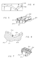
- the channel wall thrust nozzle 10 is constructed with the use of a mandrel 20, as viewed in FIG. 2.
- This mandrel 20 is formed from a selected metal or composite material or the like as by machining with relatively close tolerances.
- the particular mandrel material is desirably selected for relative dimensional stability, including thermal stability throughout normal processing temperatures which conveniently correspond with ambient air temperatures ranging typically on the order of about 60-100°F.
- the mandrel 20 is constructed with precision tolerances, the mandrel is reusable in the production of a succession of thrust nozzles without requiring complex or costly close tolerance machining operations to be performed on each thrust nozzle.
- the mandrel 20 has a generally cylindrical size and shape to define a circular transverse cross-section.
- the diametric size of the mandrel is contoured for general conformance with the geometry of the thrust chamber 12 to be constructed. That is, the mandrel 20 has a diametric size which smoothly diminishes or converges from one end to define the upstream converging portion of the thrust chamber, and then smoothly increases or diverges from a narrow throat to define the downstream diverging portion of the thrust chamber.
- the diametric size of tee mandrel from end to end is slightly less than the diametric size of the corresponding thrust chamber to be formed.
- the mandrel 20 is transversely split to define longitudinally separable mandrel components 21 and 22.
- the exterior periphery of the mandrel 20 is shaped by precision machining or the like to define an array of longitudinally extending shallow slots 24. These slots 24 are desirably formed identical to each other and with uniform circumferential spacing. The slots 24 follow the exterior contour of the mandrel 20, typically with uniform depth, from one end of the mandrel to the other. Accordingly, the slots 24 transition smoothly over the converging mandrel component 21 and then extend smoothly without interruption over the diverging mandrel component 22.
- channel separator ribs 26 are conveniently formed from appropriate metal sheet stock 28 or the like to have contoured longitudinal edge margins which generally conform to the converging-diverging geometry of the mandrel 20.
- These channel separator ribs 26 are formed from a selected material having relatively high thermal conductivity such as copper, copper alloy, or other metal material preferably having a substantially uniform sheet thickness.
- the ribs 26 can be formed in production quantities by die cutting or stamping, with multiple ribs 26 typically being cut from a single sheet of material. Mechanical or chemical deburring of the cut edges/margins of the separator ribs 26 is normally desired.
- the channel separator ribs 26 are seated individually within the mandrel slots 24 to form radially oriented walls defining the process fluid flow channels 16 therebetween, as viewed in FIG. 5.
- the radially inboard edge margins of the separator ribs 26 are anchored within the mandrel slots 24, such that the outboard margins of the ribs terminate at diametric positions disposed outwardly from the mandrel (FIGS. 5 and 6).
- the longitudinally extending channels 16 between the ribs 26 are then filled with a suitable removable casting material 30 such as a casting wax, as shown in FIG. 7.
- the outer geometry of the resultant subassembly, including the mandrel 20, the ribs 26 and the casting material 30, is then shaped to a precision converging-diverging contour by relatively easy machining or the like.
- An outer housing shell 32 (FIG. 8) is then applied to the subassembly to enclose the outboard side of the process fluid channels 16 and to define an outboard wall for the thrust nozzle 10.
- This outer housing shell 32 is normally formed from a high strength structural material, such as nickel based alloy or the like, in accordance with various manufacturing processes such as electrodeposition, or by structural mounting of preformed housing components formed from selected sheet material or the like.
- the outer housing shell 32 is joined to the outboard edge margin of each separator rib 26. When performed sheet material components are used to form the outer shell, such joining step may be performed by welding, diffusion bonding, etc.
- the mandrel 20 is separated from the partially formed thrust nozzle.
- Such separation of the mandrel 20 is accomplished quickly and easily by axial separation of the mandrel components 21 and 22.
- the converging-diverging geometry or the ribs 26 permits this separation without binding of components. Frictional resistance to separation can be minimized by precoating the mandrel 20 with a suitable release agent prior to placement of the ribs 26.
- the inboard edge margins of the separator ribs 26 are exposed (FIGS. 9 and 10). These inboard rib edges are shaped to a precision converging-diverging contour by relatively easy machining or the like. For ease of production with relatively close tolerances, the ribs 26 are machined to bridge at least slightly into the casting material 30, as shown in FIG. 11, thereby defining a precision inboard surface.
- An inner housing shell 34 of a selected material such as a copper or copper alloy having high thermal conductivity is then formed to line the interior of the nozzle subassembly, as viewed in FIG. 12. This inner shell 34 may also be formed by electrodeposition, or other suitable wall forming techniques.
- the inner shell 34 is also joined to the edges of the separator ribs 26, such that the inner and outer housing shells 34 and 32 cooperate with the separator ribs 26 to define and enclose the longitudinal process fluid channels 16.
- the casting material 30 is then removed from the channels 16 by melting and/or solvent flushing to form the finished thrust nozzle structure as depicted in FIG. 13.
- the finished thrust nozzle 10 is appropriately equipped with manifolds (not shown) for circulating the process fluid to and from the circumferential array of channels 16 during engine operation, as depicted by arrows 18 in FIG. 1.
- the improved production method of the present invention thus provides a rapid and relatively economical technique for precision formation of the channeled wall thrust nozzle. Complex machining of precision contoured channels is not required. Instead, a preformed mandrel is used as the nozzle base, wherein this mandrel includes precision channels but is reusable in the production of a succession of thrust nozzles.
Landscapes
- Engineering & Computer Science (AREA)
- Chemical & Material Sciences (AREA)
- Combustion & Propulsion (AREA)
- Mechanical Engineering (AREA)
- General Engineering & Computer Science (AREA)
- Fuel-Injection Apparatus (AREA)
- Injection Moulding Of Plastics Or The Like (AREA)
- Cylinder Crankcases Of Internal Combustion Engines (AREA)
Applications Claiming Priority (2)
| Application Number | Priority Date | Filing Date | Title |
|---|---|---|---|
| US398552 | 1989-08-25 | ||
| US07/398,552 US4942653A (en) | 1989-08-25 | 1989-08-25 | Production method for a channeled wall thrust nozzle |
Publications (2)
| Publication Number | Publication Date |
|---|---|
| EP0413983A1 true EP0413983A1 (fr) | 1991-02-27 |
| EP0413983B1 EP0413983B1 (fr) | 1993-09-15 |
Family
ID=23575816
Family Applications (1)
| Application Number | Title | Priority Date | Filing Date |
|---|---|---|---|
| EP90114189A Expired - Lifetime EP0413983B1 (fr) | 1989-08-25 | 1990-07-24 | Méthode de fabrication d'une paroi avec canaux de refroidissement pour une tuyère à réaction |
Country Status (4)
| Country | Link |
|---|---|
| US (1) | US4942653A (fr) |
| EP (1) | EP0413983B1 (fr) |
| JP (1) | JPH0396644A (fr) |
| DE (1) | DE69003334T2 (fr) |
Cited By (3)
| Publication number | Priority date | Publication date | Assignee | Title |
|---|---|---|---|---|
| EP0943795A1 (fr) * | 1998-03-20 | 1999-09-22 | Societe Nationale D'etude Et De Construction De Moteurs D'aviation "Snecma" | Procédé de fabrication d'un circuit régénératif à fort flux thermique, notamment pour chambre de combustion de moteur-fusée |
| RU2213877C2 (ru) * | 1997-12-18 | 2003-10-10 | Юнайтед Текнолоджиз Корпорейшн | Способ и технологическая оснастка для изготовления твердотопливного ракетного двигателя |
| US11779985B1 (en) * | 2020-11-15 | 2023-10-10 | Herbert U. Fluhler | Fabricating method for low cost liquid fueled rocket engines |
Families Citing this family (31)
| Publication number | Priority date | Publication date | Assignee | Title |
|---|---|---|---|---|
| NZ236008A (en) * | 1989-11-10 | 1992-12-23 | Ishida Scale Mfg Co Ltd | Packaging apparatus has film roll support and film transporting device that are width adjustable |
| US5075966A (en) * | 1990-09-04 | 1991-12-31 | General Electric Company | Method for fabricating a hollow component for a rocket engine |
| US5124106A (en) * | 1991-03-25 | 1992-06-23 | Zimmer, Inc. | Method of making a femoral rasp |
| US5386628A (en) * | 1991-12-23 | 1995-02-07 | United Technologies Corporation | Method of making a diffusion bonded rocket chamber |
| US5371945A (en) * | 1991-12-23 | 1994-12-13 | United Technologies Corporation | Method of making a tubular combustion chamber construction |
| US5467528A (en) * | 1991-12-23 | 1995-11-21 | United Technologies Corporation | Method of making a tubular thermal structure |
| US5375325A (en) * | 1992-05-26 | 1994-12-27 | United Technologies Corporation | Method of making a rocket chamber construction |
| US5249357A (en) * | 1993-01-27 | 1993-10-05 | The United States Of America As Represented By The Administrator Of The National Aeronautics And Space Administration | Method of fabricating a rocket engine combustion chamber |
| US5473817A (en) * | 1993-12-21 | 1995-12-12 | United Technologies Corporation | Method of making cooled rocket combustion chamber construction |
| US5613299A (en) * | 1994-11-09 | 1997-03-25 | Ring; Peter J. | Method of fabricating a rocket thrust chamber |
| US5546656A (en) * | 1994-11-30 | 1996-08-20 | United Technologies Corporation | Fabrication of rocket thrust chambers |
| JP4271866B2 (ja) * | 1998-11-27 | 2009-06-03 | ボルボ エアロ コーポレイション | 冷却されるノズル壁を有するロケットノズルのノズル構造 |
| US6205661B1 (en) | 1999-04-15 | 2001-03-27 | Peter John Ring | Method of making a rocket thrust chamber |
| WO2001002131A1 (fr) * | 1999-07-07 | 2001-01-11 | Russell Air-O-Nautical | Procede de production d'un appareil a paroi canaliculee |
| US7188417B2 (en) * | 2002-06-28 | 2007-03-13 | United Technologies Corporation | Advanced L-channel welded nozzle design |
| US6688100B1 (en) * | 2002-07-16 | 2004-02-10 | The Boeing Company | Combustion chamber having a multiple-piece liner and associated assembly method |
| US7493691B2 (en) * | 2004-05-20 | 2009-02-24 | Honeywell International Inc. | Co-molding metallic-lined phenolic components |
| US7596940B2 (en) * | 2005-03-22 | 2009-10-06 | Pratt & Whitney Rocketdyne, Inc. | Rocket engine nozzle and method of fabricating a rocket engine nozzle using pressure brazing |
| US8286348B2 (en) * | 2008-09-22 | 2012-10-16 | Mtu Aero Engines Gmbh | Method of manufacturing and refinishing integrally bladed rotors |
| US8025499B2 (en) | 2008-11-03 | 2011-09-27 | Rohr, Inc. | Multi-segment tool and method for composite formation |
| CN101733614B (zh) * | 2008-11-20 | 2011-12-07 | 中国兵器工业第五九研究所 | 一种火箭发动机喷管的制备方法以及其专用设备 |
| US9835114B1 (en) | 2017-06-06 | 2017-12-05 | The United States Of America As Represented By The Administrator Of Nasa | Freeform deposition method for coolant channel closeout |
| US11092111B1 (en) | 2018-12-10 | 2021-08-17 | United Launch Alliance, L.L.C. | Vapor retention device |
| CN111375690B (zh) * | 2018-12-27 | 2022-04-12 | 航天海鹰(哈尔滨)钛业有限公司 | 一种钛合金变曲率双向应力结构钣金件的热压成形方法 |
| CN110202320B (zh) * | 2019-03-15 | 2024-06-04 | 蓝箭航天技术有限公司 | 用于推力室制备工艺的复合工装及推力室制备工艺 |
| CN110666538B (zh) * | 2019-10-09 | 2020-11-13 | 北京星航机电装备有限公司 | 一种基于四轴机床的半封闭五轴特征曲面的加工方法 |
| CN112832929B (zh) * | 2021-03-05 | 2022-05-24 | 中国科学院力学研究所 | 一种用于火箭发动机的等内壁面温度的冷却结构设计方法 |
| CN112832930B (zh) * | 2021-03-05 | 2022-02-25 | 中国科学院力学研究所 | 一种用于火箭发动机的等水力直径的冷却通道设计方法 |
| CN113894453B (zh) * | 2021-09-15 | 2022-06-17 | 蓝箭航天空间科技股份有限公司 | 一种异种金属的燃烧室结构的加工方法及燃烧室 |
| CN113828793B (zh) * | 2021-10-12 | 2022-07-12 | 广东省科学院新材料研究所 | 一种火箭发动机推力室夹壁结构及其制造方法 |
| CN116038171B (zh) * | 2023-03-30 | 2023-06-27 | 北京星河动力装备科技有限公司 | 再生冷却推力室及其制作方法 |
Citations (7)
| Publication number | Priority date | Publication date | Assignee | Title |
|---|---|---|---|---|
| FR1352892A (fr) * | 1962-12-21 | 1964-02-21 | Studebaker Corp | éléments à parois stratifiées en contact avec une circulation de fluide animée d'une vitesse élevée |
| DE1264160B (de) * | 1966-12-15 | 1968-03-21 | Boelkow Gmbh | Fluessigkeitsgekuehlte Bauteile, wie Raketenbrennkammern, und Verfahren zu deren Herstellung |
| US3578030A (en) * | 1967-09-27 | 1971-05-11 | Hitco | Ablative and insulative structures |
| US3665573A (en) * | 1970-05-18 | 1972-05-30 | Atomic Energy Commission | Method of fabricating a heat pipe |
| US3910039A (en) * | 1972-09-14 | 1975-10-07 | Nasa | Rocket chamber and method of making |
| FR2374519A1 (fr) * | 1976-12-18 | 1978-07-13 | Messerschmitt Boelkow Blohm | Procede de fabrication de chambres de combustion pour fusees et de tuyeres de poussee a refroidissement regeneratif |
| EP0284410A1 (fr) * | 1987-03-26 | 1988-09-28 | Director General Of Institute Of Space And Astronautical Science | Chambre de combustion pour fusées |
Family Cites Families (7)
| Publication number | Priority date | Publication date | Assignee | Title |
|---|---|---|---|---|
| GB843923A (en) * | 1957-01-17 | 1960-08-10 | Havilland Engine Co Ltd | Apparatus in which heat exchange takes place between fluids |
| US3349464A (en) * | 1962-06-29 | 1967-10-31 | Aerojet General Co | Method of making rocket combustion chamber |
| US3529054A (en) * | 1967-11-15 | 1970-09-15 | Burroughs Corp | Method for fabricating printing drums |
| US3613207A (en) * | 1969-06-05 | 1971-10-19 | Messerschmitt Boelkow Blohm | Method for covering and closing cooling channels of a combustion chamber |
| US3692637A (en) * | 1969-11-24 | 1972-09-19 | Carl Helmut Dederra | Method of fabricating a hollow structure having cooling channels |
| JPS6082603A (ja) * | 1983-10-07 | 1985-05-10 | Natl Aerospace Lab | ロケツト燃焼器製作法 |
| US4707225A (en) * | 1986-01-06 | 1987-11-17 | Rockwell International Corporation | Fluid-cooled channel construction |
-
1989
- 1989-08-25 US US07/398,552 patent/US4942653A/en not_active Expired - Fee Related
-
1990
- 1990-07-24 DE DE90114189T patent/DE69003334T2/de not_active Expired - Fee Related
- 1990-07-24 EP EP90114189A patent/EP0413983B1/fr not_active Expired - Lifetime
- 1990-08-27 JP JP2222669A patent/JPH0396644A/ja active Pending
Patent Citations (7)
| Publication number | Priority date | Publication date | Assignee | Title |
|---|---|---|---|---|
| FR1352892A (fr) * | 1962-12-21 | 1964-02-21 | Studebaker Corp | éléments à parois stratifiées en contact avec une circulation de fluide animée d'une vitesse élevée |
| DE1264160B (de) * | 1966-12-15 | 1968-03-21 | Boelkow Gmbh | Fluessigkeitsgekuehlte Bauteile, wie Raketenbrennkammern, und Verfahren zu deren Herstellung |
| US3578030A (en) * | 1967-09-27 | 1971-05-11 | Hitco | Ablative and insulative structures |
| US3665573A (en) * | 1970-05-18 | 1972-05-30 | Atomic Energy Commission | Method of fabricating a heat pipe |
| US3910039A (en) * | 1972-09-14 | 1975-10-07 | Nasa | Rocket chamber and method of making |
| FR2374519A1 (fr) * | 1976-12-18 | 1978-07-13 | Messerschmitt Boelkow Blohm | Procede de fabrication de chambres de combustion pour fusees et de tuyeres de poussee a refroidissement regeneratif |
| EP0284410A1 (fr) * | 1987-03-26 | 1988-09-28 | Director General Of Institute Of Space And Astronautical Science | Chambre de combustion pour fusées |
Cited By (6)
| Publication number | Priority date | Publication date | Assignee | Title |
|---|---|---|---|---|
| RU2213877C2 (ru) * | 1997-12-18 | 2003-10-10 | Юнайтед Текнолоджиз Корпорейшн | Способ и технологическая оснастка для изготовления твердотопливного ракетного двигателя |
| EP0943795A1 (fr) * | 1998-03-20 | 1999-09-22 | Societe Nationale D'etude Et De Construction De Moteurs D'aviation "Snecma" | Procédé de fabrication d'un circuit régénératif à fort flux thermique, notamment pour chambre de combustion de moteur-fusée |
| FR2776215A1 (fr) * | 1998-03-20 | 1999-09-24 | Snecma | Procede de fabrication d'un circuit regeneratif a fort flux thermique, notamment pour chambre de combustion de moteur-fusee |
| US6209199B1 (en) | 1998-03-20 | 2001-04-03 | Societe Nationale D'etude Et De Construction De Moteurs D'aviation- S.N.E.C.M.A. | Method of manufacturing a high heat flux regenerative circuit, in particular for the combustion chamber of a rocket engine |
| US6516872B1 (en) | 1998-03-20 | 2003-02-11 | Societe Nationale D'etude Et De Construction De Moteurs D'aviation -S.N.E.C.M.A. | High heat flux regenerative circuit, in particular for the combustion chamber of a rocket engine |
| US11779985B1 (en) * | 2020-11-15 | 2023-10-10 | Herbert U. Fluhler | Fabricating method for low cost liquid fueled rocket engines |
Also Published As
| Publication number | Publication date |
|---|---|
| US4942653A (en) | 1990-07-24 |
| DE69003334T2 (de) | 1994-04-21 |
| EP0413983B1 (fr) | 1993-09-15 |
| JPH0396644A (ja) | 1991-04-22 |
| DE69003334D1 (de) | 1993-10-21 |
Similar Documents
| Publication | Publication Date | Title |
|---|---|---|
| EP0413983B1 (fr) | Méthode de fabrication d'une paroi avec canaux de refroidissement pour une tuyère à réaction | |
| US6003756A (en) | Airfoil for gas a turbine engine and method of manufacture | |
| US3786755A (en) | Plastic cartridge casing | |
| EP0113882B1 (fr) | Méthode de fabrication d'un produit ayant un passage de fluide | |
| EP0086036B1 (fr) | Procédé et dispositif de formage d'une pièce cylindrique, notamment d'un connecteur électrique | |
| US6668906B2 (en) | Shaped core for cast cooling passages and enhanced part definition | |
| US4156306A (en) | Method of manufacturing regeneratively cooled rocket combustion chambers | |
| US5701670A (en) | Method of making rocket engine combustion chamber utilizing "slide in" port liner | |
| US6516872B1 (en) | High heat flux regenerative circuit, in particular for the combustion chamber of a rocket engine | |
| US6158961A (en) | Truncated chamfer turbine blade | |
| US3858290A (en) | Method of making inserts for cooled turbine blades | |
| EP3267110B1 (fr) | Procédé de production d'une chambre de combustion | |
| JP2005186268A (ja) | 案内装置 | |
| EP4031750B1 (fr) | Dispositif de guidage avec une virole integrée ayant de l'épaisseur optimisée de parois de l'aube de guidage | |
| CA1134649A (fr) | Matrice de forgeage | |
| US5473817A (en) | Method of making cooled rocket combustion chamber construction | |
| EP3181262B1 (fr) | Procédé et ensemble pour former des composants ayant un passage interne délimité en leur sein | |
| US20070137278A1 (en) | Trimless forged products and method | |
| US6431830B1 (en) | Nozzle ring for a gas turbine | |
| US6901661B2 (en) | Method for manufacturing a vane to a gas turbine component and a method for manufacturing a gas turbine component | |
| EP3954477B1 (fr) | Outillage et méthode pour former des composants de nacelle | |
| JPH0760340A (ja) | 高力系アルミニウム合金製中空材の押出方法 | |
| JPS5816585B2 (ja) | マグネトロンアノ−ドノ セイゾウホウホウ |
Legal Events
| Date | Code | Title | Description |
|---|---|---|---|
| PUAI | Public reference made under article 153(3) epc to a published international application that has entered the european phase |
Free format text: ORIGINAL CODE: 0009012 |
|
| AK | Designated contracting states |
Kind code of ref document: A1 Designated state(s): DE FR GB IT SE |
|
| 17P | Request for examination filed |
Effective date: 19910812 |
|
| 17Q | First examination report despatched |
Effective date: 19921201 |
|
| GRAA | (expected) grant |
Free format text: ORIGINAL CODE: 0009210 |
|
| AK | Designated contracting states |
Kind code of ref document: B1 Designated state(s): DE FR GB IT SE |
|
| ITF | It: translation for a ep patent filed | ||
| REF | Corresponds to: |
Ref document number: 69003334 Country of ref document: DE Date of ref document: 19931021 |
|
| ET | Fr: translation filed | ||
| PLBE | No opposition filed within time limit |
Free format text: ORIGINAL CODE: 0009261 |
|
| STAA | Information on the status of an ep patent application or granted ep patent |
Free format text: STATUS: NO OPPOSITION FILED WITHIN TIME LIMIT |
|
| 26N | No opposition filed | ||
| REG | Reference to a national code |
Ref country code: FR Ref legal event code: CA |
|
| EAL | Se: european patent in force in sweden |
Ref document number: 90114189.5 |
|
| PGFP | Annual fee paid to national office [announced via postgrant information from national office to epo] |
Ref country code: SE Payment date: 19970619 Year of fee payment: 8 |
|
| PGFP | Annual fee paid to national office [announced via postgrant information from national office to epo] |
Ref country code: FR Payment date: 19970620 Year of fee payment: 8 |
|
| PGFP | Annual fee paid to national office [announced via postgrant information from national office to epo] |
Ref country code: DE Payment date: 19970624 Year of fee payment: 8 |
|
| PGFP | Annual fee paid to national office [announced via postgrant information from national office to epo] |
Ref country code: GB Payment date: 19970626 Year of fee payment: 8 |
|
| PG25 | Lapsed in a contracting state [announced via postgrant information from national office to epo] |
Ref country code: GB Free format text: LAPSE BECAUSE OF NON-PAYMENT OF DUE FEES Effective date: 19980724 |
|
| PG25 | Lapsed in a contracting state [announced via postgrant information from national office to epo] |
Ref country code: SE Free format text: LAPSE BECAUSE OF NON-PAYMENT OF DUE FEES Effective date: 19980725 |
|
| GBPC | Gb: european patent ceased through non-payment of renewal fee |
Effective date: 19980724 |
|
| EUG | Se: european patent has lapsed |
Ref document number: 90114189.5 |
|
| PG25 | Lapsed in a contracting state [announced via postgrant information from national office to epo] |
Ref country code: FR Free format text: LAPSE BECAUSE OF NON-PAYMENT OF DUE FEES Effective date: 19990331 |
|
| PG25 | Lapsed in a contracting state [announced via postgrant information from national office to epo] |
Ref country code: DE Free format text: LAPSE BECAUSE OF NON-PAYMENT OF DUE FEES Effective date: 19990501 |
|
| REG | Reference to a national code |
Ref country code: FR Ref legal event code: ST |
|
| PG25 | Lapsed in a contracting state [announced via postgrant information from national office to epo] |
Ref country code: IT Free format text: LAPSE BECAUSE OF NON-PAYMENT OF DUE FEES Effective date: 20050724 |