EP0414033A1 - Méthode pour le transfert continu d'électrolyte et électrodes de référence - Google Patents
Méthode pour le transfert continu d'électrolyte et électrodes de référence Download PDFInfo
- Publication number
- EP0414033A1 EP0414033A1 EP90115119A EP90115119A EP0414033A1 EP 0414033 A1 EP0414033 A1 EP 0414033A1 EP 90115119 A EP90115119 A EP 90115119A EP 90115119 A EP90115119 A EP 90115119A EP 0414033 A1 EP0414033 A1 EP 0414033A1
- Authority
- EP
- European Patent Office
- Prior art keywords
- electrolyte
- electrode
- electrode insert
- insert
- bearing tube
- Prior art date
- Legal status (The legal status is an assumption and is not a legal conclusion. Google has not performed a legal analysis and makes no representation as to the accuracy of the status listed.)
- Granted
Links
- 239000003792 electrolyte Substances 0.000 title claims abstract description 80
- 238000000034 method Methods 0.000 title claims description 19
- 238000012546 transfer Methods 0.000 title description 2
- 230000007246 mechanism Effects 0.000 claims abstract description 16
- 239000007788 liquid Substances 0.000 claims abstract description 9
- 239000011244 liquid electrolyte Substances 0.000 claims abstract description 6
- 238000005259 measurement Methods 0.000 claims description 5
- 238000004140 cleaning Methods 0.000 claims description 3
- 230000001360 synchronised effect Effects 0.000 claims description 3
- 238000011010 flushing procedure Methods 0.000 claims description 2
- 238000013494 PH determination Methods 0.000 claims 2
- 239000013641 positive control Substances 0.000 claims 2
- 230000008878 coupling Effects 0.000 claims 1
- 238000010168 coupling process Methods 0.000 claims 1
- 238000005859 coupling reaction Methods 0.000 claims 1
- 238000009423 ventilation Methods 0.000 claims 1
- 239000012528 membrane Substances 0.000 abstract description 4
- 238000012423 maintenance Methods 0.000 description 7
- 239000011521 glass Substances 0.000 description 6
- 230000008901 benefit Effects 0.000 description 5
- 230000008569 process Effects 0.000 description 5
- 230000007704 transition Effects 0.000 description 5
- 230000008859 change Effects 0.000 description 4
- 230000006870 function Effects 0.000 description 4
- 239000000499 gel Substances 0.000 description 4
- 238000003780 insertion Methods 0.000 description 4
- 230000037431 insertion Effects 0.000 description 4
- 238000007789 sealing Methods 0.000 description 3
- 229910021607 Silver chloride Inorganic materials 0.000 description 2
- 230000006378 damage Effects 0.000 description 2
- 230000001419 dependent effect Effects 0.000 description 2
- 238000013461 design Methods 0.000 description 2
- 238000009792 diffusion process Methods 0.000 description 2
- 238000006073 displacement reaction Methods 0.000 description 2
- BASFCYQUMIYNBI-UHFFFAOYSA-N platinum Chemical compound [Pt] BASFCYQUMIYNBI-UHFFFAOYSA-N 0.000 description 2
- 231100000572 poisoning Toxicity 0.000 description 2
- 230000000607 poisoning effect Effects 0.000 description 2
- FGIUAXJPYTZDNR-UHFFFAOYSA-N potassium nitrate Chemical compound [K+].[O-][N+]([O-])=O FGIUAXJPYTZDNR-UHFFFAOYSA-N 0.000 description 2
- 229910052709 silver Inorganic materials 0.000 description 2
- 239000004332 silver Substances 0.000 description 2
- HKZLPVFGJNLROG-UHFFFAOYSA-M silver monochloride Chemical compound [Cl-].[Ag+] HKZLPVFGJNLROG-UHFFFAOYSA-M 0.000 description 2
- 229920001817 Agar Polymers 0.000 description 1
- VEXZGXHMUGYJMC-UHFFFAOYSA-M Chloride anion Chemical compound [Cl-] VEXZGXHMUGYJMC-UHFFFAOYSA-M 0.000 description 1
- 241000206672 Gelidium Species 0.000 description 1
- -1 KCl ions Chemical class 0.000 description 1
- 239000004809 Teflon Substances 0.000 description 1
- 229920006362 Teflon® Polymers 0.000 description 1
- 230000004913 activation Effects 0.000 description 1
- 235000010419 agar Nutrition 0.000 description 1
- 239000000919 ceramic Substances 0.000 description 1
- 238000011109 contamination Methods 0.000 description 1
- 238000002425 crystallisation Methods 0.000 description 1
- 230000008025 crystallization Effects 0.000 description 1
- 238000009795 derivation Methods 0.000 description 1
- 238000011161 development Methods 0.000 description 1
- 230000018109 developmental process Effects 0.000 description 1
- 230000000694 effects Effects 0.000 description 1
- 238000007654 immersion Methods 0.000 description 1
- 230000006872 improvement Effects 0.000 description 1
- 230000003993 interaction Effects 0.000 description 1
- 238000002386 leaching Methods 0.000 description 1
- 239000000463 material Substances 0.000 description 1
- 239000002808 molecular sieve Substances 0.000 description 1
- 238000012544 monitoring process Methods 0.000 description 1
- 238000001139 pH measurement Methods 0.000 description 1
- 229910052697 platinum Inorganic materials 0.000 description 1
- 235000010333 potassium nitrate Nutrition 0.000 description 1
- 108090000623 proteins and genes Proteins 0.000 description 1
- 230000009467 reduction Effects 0.000 description 1
- 230000002441 reversible effect Effects 0.000 description 1
- URGAHOPLAPQHLN-UHFFFAOYSA-N sodium aluminosilicate Chemical compound [Na+].[Al+3].[O-][Si]([O-])=O.[O-][Si]([O-])=O URGAHOPLAPQHLN-UHFFFAOYSA-N 0.000 description 1
- 230000003068 static effect Effects 0.000 description 1
- 238000013022 venting Methods 0.000 description 1
- XLYOFNOQVPJJNP-UHFFFAOYSA-N water Substances O XLYOFNOQVPJJNP-UHFFFAOYSA-N 0.000 description 1
Images

Classifications
-
- G—PHYSICS
- G01—MEASURING; TESTING
- G01N—INVESTIGATING OR ANALYSING MATERIALS BY DETERMINING THEIR CHEMICAL OR PHYSICAL PROPERTIES
- G01N27/00—Investigating or analysing materials by the use of electric, electrochemical, or magnetic means
- G01N27/26—Investigating or analysing materials by the use of electric, electrochemical, or magnetic means by investigating electrochemical variables; by using electrolysis or electrophoresis
- G01N27/28—Electrolytic cell components
- G01N27/30—Electrodes, e.g. test electrodes; Half-cells
- G01N27/301—Reference electrodes
-
- G—PHYSICS
- G01—MEASURING; TESTING
- G01N—INVESTIGATING OR ANALYSING MATERIALS BY DETERMINING THEIR CHEMICAL OR PHYSICAL PROPERTIES
- G01N27/00—Investigating or analysing materials by the use of electric, electrochemical, or magnetic means
- G01N27/26—Investigating or analysing materials by the use of electric, electrochemical, or magnetic means by investigating electrochemical variables; by using electrolysis or electrophoresis
- G01N27/28—Electrolytic cell components
- G01N27/401—Salt-bridge leaks; Liquid junctions
Definitions
- the invention is based on a method for the continuous supply of electrolyte to a reference electrode according to the preamble of claim 1 and a reference electrode system according to the preamble of claim 9 for carrying out the method.
- Reference systems in analytical chemistry i.e. reference electrodes that provide a constant reference potential, in particular for pH and redox measurement, are known (DE-OS 32 03 406, DE-OS 32 03 407, DE-OS 34 11 800 and finally also European patent application 0299372 A2), also in the form of so-called electrolyte bridge systems with two diaphragms connected in series or in the form of a combination electrode, for example suitable for pH measurement (pH combination electrode), in which the pH-sensitive electrode and the reference electrode are housed together in a glass tube.
- pH combination electrode pH combination electrode
- the known reference electrodes use diffusion transitions in various forms, for example as a ceramic diaphragm, platinum diaphragm, teflon diaphragm, but also very small hole openings made in the side wall of the glass tube, the reference electrode electrolyte used being a KCl or a KNO 3 solution in liquid form or a gel of suitable consistency can and then consists, for example, of agar-agar, of polyacrylic material or of PVC. Such a gel acts as a molecular sieve, in which KCl ions are then usually embedded.
- Reference electrodes usually contain a half cell made of silver / silver chloride, which is immersed in a solution of constant chloride ion concentration. This solution is then connected to the measuring medium via the diaphragm provided in each case.
- the diaphragm forming a gate for the reference electrolyte to the measuring medium can cause diffusion in both directions, for example caused by concentration differences or pressure differences between the reference electrolyte and the measuring medium. Blockage of the diaphragm by crystallization or its clogging with other media is also possible. Finally, poisoning of the reference electrolyte and the lead system from the measuring medium cannot be ruled out.
- a very frequently used way of avoiding a large number of problems arising in the area of the reference electrolyte and its diaphragm is to provide a reference system with a flowing electrolyte, liquid reference electrolyte being introduced into the chamber containing the electrolyte under a specially generated pressure or via a suitable inflow fitting is also supplied only by the static water column pressure.
- the electrolyte then develops a general flow towards and through the diaphragm so that very small amounts of reference electrolyte continuously enter the measuring medium, but on the other hand the reference system is maintained in perfect condition and the diaphragm is cleaned and rinsed from the inside so that poisoning does not occur can.
- the inner electrolyte can also be a gel which is connected via a first inner diaphragm to a further outer chamber which is then immersed in the measuring medium via an outer diaphragm. It is then the liquid electrolyte in the outer chamber that emerges as a flowing electrolyte through the outer diaphragm and thereby flows past the inner, for example higher, diaphragm.
- the supply of the flowing electrolyte is particularly cumbersome since it has previously been necessary to space the receiving reference electrolyte via an outward-pointing branch, that is to say, for example, in the case of a combination electrode, an angled one upwards To connect glass tubes and a hose connection attached to this with a reference electrolyte KCl or KNO3 containing vessel.
- the electrolyte then flows via this hose and inflow fitting connection into the electrolyte chamber at such a pressure that any back pressure of the measuring medium is overcome.
- the first thing to do to change the electrode is to release the pressure in the reference electrolyte, then empty the KCl vessel, empty the hose, disconnect the hose, bleed the system, then you can remove the electrode with caution, with the reference electrolyte dripping all over and have to do these steps when reinstalling, perform the procedure in reverse order and bleed the system.
- the invention is therefore based on the object to remedy this situation and to enable an electrode change in a "flowing reference electrode", even in the form of a combination electrode, without having to worry about the flowing reference electrolyte and its interruption at all, also if this should be under considerable pressure.
- the invention solves this problem with the mark the features of the main claim and has the advantage that with a corresponding redesign of the possible uses of the electrode part in the socket, the mount or an outer bearing tube in the usually manual change (removal and use of the electrode part in the bearing tube) automatic monitoring and interruption and reopening of the Electrolyte supply takes place, the electrolyte inflow being routed from the outside inwards and therefore no disruptive hose connections need to be connected to connection glass tubes on the outside.
- This not only reduces the possible risk of breakage, but also the total outlay for such measuring systems in analytical chemistry, which work with a refillable rinsing electrolyte, in a decisive manner both in terms of maintenance and operating effort and in terms of the complexity of the structural design.
- the accuracy of the measuring system is increased by the invention, since it is always ensured that faults do not occur due to human inadequacy during maintenance or reconnection, which under certain circumstances may only be noticed much later and can lead to considerable damage in continuously running processes.
- Another decisive advantage of the present invention is that the otherwise practically unavoidable messing with the liquid rinsing electrolyte for the reference electrode is completely eliminated, which is not only due to the connection and disconnection of the hose Connections arises, but also because, for example after maintenance or replacement of the electrode part, it must also be vented, especially since the otherwise necessary frequent disconnection of a hose connection does not contribute to its tightness.
- the invention can be applied to any type of reference electrode, preferably in combination with combination electrodes, in which an electrode insert in the form of an electrode part comprising an inner support tube is inserted into an outer support tube or a receiving mount standardized for certain applications, which in turn has to be used Flange connections in the area of the medium to be immersed in it.
- the invention is therefore also particularly suitable for electrode holders which connect a suitable measuring electrode, for example pH electrode, to a measuring medium, for example in the form of a flow-through, add-on fitting or immersion fitting.
- a suitable measuring electrode for example pH electrode
- a measuring medium for example in the form of a flow-through, add-on fitting or immersion fitting.
- the mounting bayonet is also insensitive to deposits of dirt or other disturbances, in contrast to threads, it does not tend to "seize” when it is actuated and also provides a noticeable relative lifting movement which ensures that seals enclosing the bayonet locking area between them run into their sealing positions.
- the present invention does not, as would be assumed, utilize the lifting movement when inserting the electrode part into the bearing tube for valve actuation, but rather the rotary movement resulting from the bayonet actuation, since this is the only way to achieve this , a closely standardized carrier mount in the field of analytical chemistry to adhere to the dimensions specified in this way (usual diameter of such a standardized carrier mount in numerical size, not restricting the invention, only 45 mm) and still one to guarantee perfect function and tightness for the "flowing electrolyte".
- a further advantageous embodiment of the present invention is to divide the insert movement into steps, for example by a corresponding additional step in the bayonet lock area, that a first insert movement brings the electrode part into the bearing tube to such an extent that the valve opening already effected thereby a venting of the flow and chamber areas of the reference electrode is possible through the already flowing reference electrolyte, which also noticeably penetrates to the outside, so that the maintenance person can determine this until the electrode part is completely inserted into the bearing tube with a further insertion end rotation and a lower end seal also closes. This then results in the security for the maintenance person that everything is put together in perfect operating function.
- the basic idea of the present invention is to automate this in a reference electrode system with a flowing electrolyte feed in such a way that the further electrolyte feed is automatically shut off and the inflow is opened again when the electrode part is removed from its holder or inserted again .
- a valve system is used to block or open the inflow, which reacts to the removal or insertion movement of the electrode part, more precisely to the rotational movement required when inserting the electrode part, which is due to a bayonet locking movement.
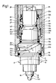
- an outer bearing tube which receives an electrode part is designated by 10; the electrode part or electrode insert designated 11 in the drawing of FIG. 1 is not shown hatched throughout for better understanding of the invention from top to bottom and itself consists of an outer stepped housing 11a with at least two ring grooves 12a, 12b and 12c, the each take up ring seals 13a, 13b, 13c, usually O-rings.
- the electrode part insert can only contain a conventional reference electrode system, with the proviso that a flowing electrolyte supply is provided for this;
- the preferred exemplary embodiment shown is the realization of an electrode part in the manner of a combination electrode, possibly also supplemented by an additional temperature sensor, it being possible for the measuring electrode part 14 with the glass membrane 14a to be arranged inwardly in the electrode insert 11, while, as shown by the dashed line Lines indicated, around the measuring electrode around the outside the electrolyte chamber 15 for the reference sy system can extend, with a diaphragm indicated at 16.
- FIG. 3 schematically and in part showing a reference electrode system 17 with a bridge electrolyte.
- the inner measuring electrode 14 ' is surrounded by a first (ring-shaped) reference electrolyte chamber 15' with silver / silver chloride derivation at 17.
- the reference electrolyte contained in the inner electrolyte chamber 15 ' can be in gel form, with a first inner diaphragm 18, which forms a transition forms an outer electrolyte chamber 19, which is then filled by the refillable rinsing electrolyte, for example KCl, which is liquid in this case and is also flowed through in accordance with the direction of the arrow, with a lower annular outer diaphragm 20, from which the outer electrolyte is then, but in a comparatively small amount Quantities also transfer into the measuring medium (indirect reference system).
- the refillable rinsing electrolyte for example KCl
- Such an electrode system like the electrode system without bridge electrolyte according to FIG. 4, is then accommodated in a suitable housing as designated by 11 in FIG. 1, with the Embodiment of the electrode system of FIG. 4 (direct reference system - the electrode of the reference system is immediately flowed through with KCl), the reference electrode ring chamber 15 ⁇ which receives the liquid reference electrolyte is pulled down to the sensitive glass membrane 14a ⁇ of the measuring electrode 14 ⁇ and there in the transition so-called ring diaphragm 21 forms.
- the electrode part receiving the liquid fillable reference electrolyte in each case being connected via corresponding internal bores and passages in the housing 11a of the electrode part to a corresponding inlet opening in the bearing tube 10 via a valve mechanism, which will be discussed further below .
- a measuring method with the reference electrode raised can also be mentioned.
- the attachment of the electrode insert 11 in the bearing tube 10 takes place by means of a threaded connection, in any case in the simplest case and then in the manner customary in the prior art, so that the electrode insert in the bearing tube is inserted from below in FIG. 1 and then screwed tight .
- the invention makes use of this screwing movement in its simultaneous rotational and axial displacement in order to open the valve mechanism already mentioned when it is removed or to close it again when it is inserted, thereby opening or interrupting the flow of liquid flushing electrolyte for the reference system.
- the “screw connection” is designed in the form of an internally located and therefore non-soiling bayonet system 22, consisting of at least one, preferably two Guide pins 23a, 23b which engage in corresponding guide slide grooves 24 (only one is visible on the housing 11a of the electrode insert).
- the basic mechanism can be readily recognized from the illustration in FIG. 1; If the electrode insert 11 is rotated in the A direction in the direction of the double arrow A / B for removal, then the interaction of the guide pins 23a, 23b with the guide tracks 24 finally pushes the electrode insert down and comes out of the bearing tube.
- the guideway (s) 24 has a first, horizontally running sub-area 24a and a part 24b, which adjoins this after a predetermined angle of rotation, for reasons connected with the activation of the valve mechanism which is thereby effected.
- the inclined part 24b of each guideway 24 ensures that due to the rotational movement and therefore with appropriate reduction, the ring seals 13a, 13b and 13c, which naturally also have a certain clamping effect, are released from their assigned seats, so that the electrode insert is then slightly pulled downwards and can be removed.
- an additional tube insert 25 is inserted into the outer bearing tube 10, although its shape and functions can also be taken over by a correspondingly machined bearing tube itself.
- the tube insert 25 or the bearing tube in any case has an inflow channel 26 for the (rinsing) electrolyte to be supplied, the inflow channel being able to be designed as a deep-hole bore in the tube insert 25 which merges into a transverse bore 27.
- This transverse bore is already part of the valve mechanism, which comprises a stepped rotating sleeve 28 received in the pipe insert via a plurality of seals.
- the transverse opening of the deep hole forming the feed channel 26 can moreover be machined in that the tube insert 25 is drilled inside to a hole diameter such that the deep hole is thereby cut.
- the further throughflow channel 26 transverse bore 27 in the rotating sleeve 28 preferably opens into an annular channel 29 in the housing 11a of the electrode insert 11, so that at each rotational position of the rotating sleeve 28 the electrolyte flow through the annular channel 29 through corresponding inner channels, not shown in detail, until into the reference electrolyte chamber of the measuring system (s) receiving the (outer) electrolyte.
- This flow of electrolyte is discernibly interrupted when the rotating sleeve 28 is rotated so far that its through bore 27 can no longer communicate with the opening of the feed channel 26, corresponding sealing means being provided which, in the preferred embodiment, consist of an annular seal, preferably O- Ring 30 can exist which is inserted into an annular channel 31 surrounding the through bore 27 in the outer wall of the rotary sleeve 28 - see also the illustration in FIG. 2, which can also be seen that a comparable seal is also provided by an oblique around the entire outer body of the rotary sleeve 28 running ring seal 30 'can be achieved.
- sealing means which, in the preferred embodiment, consist of an annular seal, preferably O- Ring 30 can exist which is inserted into an annular channel 31 surrounding the through bore 27 in the outer wall of the rotary sleeve 28 - see also the illustration in FIG. 2, which can also be seen that a comparable seal is also provided by an oblique around the entire outer body of the rotary sleeve 28 running
- the rotating sleeve 28 is sealed to the outside and to the inside by a large number of further ring seals in the form of O-rings 32a, 32b, 32c.
- the rotary sleeve 28 has at least one driver pin 33, which engages in a suitably designed link guide 34, which is incorporated in the outer wall of the electrode insert body.
- a suitably designed link guide 34 which is incorporated in the outer wall of the electrode insert body.
- the guide or driver pins can thus each be arranged on the housing of the electrode insert, while the guide tracks are inner ring tracks on the bearing tube 10 or the rotating sleeve 28.
- the link guide 34 is made such that it comprises a vertical groove area 34a, in which the guide pin 33 is in the complete operating position according to FIG. 1, and a sub-area 34b adjoining it at a right angle transition with a horizontal course. In the latter case there is no upper limit, as can also be seen in the illustration in FIG. 2.
- the guide pin 23a preferably does not enter the oblique course 24b of the bayonet path until the valve is completely closed, as a result of which the electrode insert 11 is simultaneously pulled down with further rotation, that is to say performs an axial movement, which means that the driver pin 33 the rotating sleeve gradually comes free from the axial part groove 34a of the link guide, the rotating sleeve 28 being rotated by further angular amounts until the driver pin has completely escaped from the axial region of the link and has been identified, for example, in FIG. 1 by 33 ' Position or at another position further to the right.
- this area 34b of the link guide for the valve actuation is a kind of free-wheeling and since the link is open at the top, the electrodes insert can be removed after the seals 13a, 13b and 13c have been released accordingly.
- the reinstallation of the electrode part after the desired maintenance, cleaning or replacement can be explained as a kinematic reversal of the process just described; the relative positions are necessarily aligned with each other by the previous removal process so that when the guide pins 23 in the bayonet area get into the guideway (s), the driver pins 33 are also correct, so that they are moved by the subsequent lifting / rotating movement of the The link guide can be caught again and the opening in the valve area takes place when the guide pins 23a continue to slide in the horizontal area 24a of the guideway when turning further.
- a preferred further embodiment of the present invention also consists in the fact that the guideway in the bayonet area can be formed in two stages, as shown in dashed lines at 24 '.
- the process is basically similar; modified, however, in that the opening of the valve already takes place when inserting the corresponding position relative to one another when starting from the starting position of the guide track 24 'shown in FIG. 1 with C' for the first time transitions into a horizontal guide area.
- the lower ring seal 13c is in any case not yet tight, while the other seals already have their respective position by a corresponding displacement gene have taken sealing seats and, as I said, the electrolyte supply already takes place when you first turn the electrode insert to the end point of the first horizontal course, which is denoted by C '. Therefore corresponds to the guideway section CC ', in which the electrode insert does not perform any axial movement, the valve opening and the electrolyte which is already flowing fills the electrolyte chamber and also vents it, since a vent opening is provided at a suitable point, for example at 36 in the reference electrolyte chamber.
Landscapes
- Chemical & Material Sciences (AREA)
- Life Sciences & Earth Sciences (AREA)
- Health & Medical Sciences (AREA)
- Physics & Mathematics (AREA)
- Chemical Kinetics & Catalysis (AREA)
- Electrochemistry (AREA)
- Molecular Biology (AREA)
- Analytical Chemistry (AREA)
- Biochemistry (AREA)
- General Health & Medical Sciences (AREA)
- General Physics & Mathematics (AREA)
- Immunology (AREA)
- Pathology (AREA)
- Investigating Or Analyzing Materials By The Use Of Electric Means (AREA)
- Hybrid Cells (AREA)
Priority Applications (1)
| Application Number | Priority Date | Filing Date | Title |
|---|---|---|---|
| AT9090115119T ATE105410T1 (de) | 1989-08-18 | 1990-08-07 | Verfahren zur kontinuierlichen elektrolytzufuehrung und referenzelektrodensystem. |
Applications Claiming Priority (4)
| Application Number | Priority Date | Filing Date | Title |
|---|---|---|---|
| DE8909902U | 1989-08-18 | ||
| DE8909902U DE8909902U1 (de) | 1989-08-18 | 1989-08-18 | Elektrodenhalterung für Eintauch-, Durchfluß- und Anbau-Meßsysteme in der analytischen Chemie |
| DE19893940948 DE3940948A1 (de) | 1989-12-12 | 1989-12-12 | Verfahren zur kontinuierlichen elektrolytzufuehrung und referenzelektrodensystem |
| DE3940948 | 1989-12-12 |
Publications (2)
| Publication Number | Publication Date |
|---|---|
| EP0414033A1 true EP0414033A1 (fr) | 1991-02-27 |
| EP0414033B1 EP0414033B1 (fr) | 1994-05-04 |
Family
ID=25887886
Family Applications (1)
| Application Number | Title | Priority Date | Filing Date |
|---|---|---|---|
| EP90115119A Expired - Lifetime EP0414033B1 (fr) | 1989-08-18 | 1990-08-07 | Méthode pour le transfert continu d'électrolyte et électrodes de référence |
Country Status (2)
| Country | Link |
|---|---|
| EP (1) | EP0414033B1 (fr) |
| DE (1) | DE59005602D1 (fr) |
Cited By (5)
| Publication number | Priority date | Publication date | Assignee | Title |
|---|---|---|---|---|
| EP0952448A1 (fr) * | 1998-04-23 | 1999-10-27 | ENDRESS + HAUSER CONDUCTA GESELLSCHAFT FÜR MESS UND REGELTECHNIK mbH & Co. | Dispositif de retenue pour capteur de mesure des fluides de traitement |
| WO1999054720A1 (fr) * | 1998-04-20 | 1999-10-28 | Gat Gamma Analysentechnik Gmbh | Chaine de mesure combinee comprenant une electrode de reference indirecte dotee d'une premiere transition de type meche et d'un diaphragme d'espace annulaire comme deuxieme transition |
| WO2004011920A1 (fr) * | 2002-07-25 | 2004-02-05 | Testo Ag | Dispositif et procede de production de pression dans l'electrolyte d'une electrode de reference |
| CN111378976A (zh) * | 2018-12-28 | 2020-07-07 | 中核核电运行管理有限公司 | 一种新型参比电极固定装置 |
| DE102018132131B4 (de) | 2018-12-13 | 2023-03-30 | Hamilton Bonaduz Ag | Einstabmesskette mit erweitertem Referenzraum und Verfahren zum Herstellen der Einstabmesskette |
Citations (5)
| Publication number | Priority date | Publication date | Assignee | Title |
|---|---|---|---|---|
| FR2407469A1 (fr) * | 1977-11-01 | 1979-05-25 | Proton Ag | Electrode de mesure pour la mesure d'ions dans des solutions |
| US4378280A (en) * | 1982-03-01 | 1983-03-29 | Graphic Controls Corporation | Fixed sleeve junction reference electrode |
| US4578170A (en) * | 1985-04-05 | 1986-03-25 | Ethylene Corp. | Mounting structure for electronic probes |
| EP0271764A2 (fr) * | 1986-12-17 | 1988-06-22 | Conducta Gesellschaft für Mess- und Regeltechnik mbH & Co. | Support pour électrodes en chimie analytique |
| DE3834240A1 (de) * | 1988-10-07 | 1990-04-12 | Gimat | Gehaeuse fuer messsonden in leitungen und verwendung des gehaeuses fuer in situ messsonden |
-
1990
- 1990-08-07 DE DE59005602T patent/DE59005602D1/de not_active Expired - Fee Related
- 1990-08-07 EP EP90115119A patent/EP0414033B1/fr not_active Expired - Lifetime
Patent Citations (5)
| Publication number | Priority date | Publication date | Assignee | Title |
|---|---|---|---|---|
| FR2407469A1 (fr) * | 1977-11-01 | 1979-05-25 | Proton Ag | Electrode de mesure pour la mesure d'ions dans des solutions |
| US4378280A (en) * | 1982-03-01 | 1983-03-29 | Graphic Controls Corporation | Fixed sleeve junction reference electrode |
| US4578170A (en) * | 1985-04-05 | 1986-03-25 | Ethylene Corp. | Mounting structure for electronic probes |
| EP0271764A2 (fr) * | 1986-12-17 | 1988-06-22 | Conducta Gesellschaft für Mess- und Regeltechnik mbH & Co. | Support pour électrodes en chimie analytique |
| DE3834240A1 (de) * | 1988-10-07 | 1990-04-12 | Gimat | Gehaeuse fuer messsonden in leitungen und verwendung des gehaeuses fuer in situ messsonden |
Cited By (5)
| Publication number | Priority date | Publication date | Assignee | Title |
|---|---|---|---|---|
| WO1999054720A1 (fr) * | 1998-04-20 | 1999-10-28 | Gat Gamma Analysentechnik Gmbh | Chaine de mesure combinee comprenant une electrode de reference indirecte dotee d'une premiere transition de type meche et d'un diaphragme d'espace annulaire comme deuxieme transition |
| EP0952448A1 (fr) * | 1998-04-23 | 1999-10-27 | ENDRESS + HAUSER CONDUCTA GESELLSCHAFT FÜR MESS UND REGELTECHNIK mbH & Co. | Dispositif de retenue pour capteur de mesure des fluides de traitement |
| WO2004011920A1 (fr) * | 2002-07-25 | 2004-02-05 | Testo Ag | Dispositif et procede de production de pression dans l'electrolyte d'une electrode de reference |
| DE102018132131B4 (de) | 2018-12-13 | 2023-03-30 | Hamilton Bonaduz Ag | Einstabmesskette mit erweitertem Referenzraum und Verfahren zum Herstellen der Einstabmesskette |
| CN111378976A (zh) * | 2018-12-28 | 2020-07-07 | 中核核电运行管理有限公司 | 一种新型参比电极固定装置 |
Also Published As
| Publication number | Publication date |
|---|---|
| EP0414033B1 (fr) | 1994-05-04 |
| DE59005602D1 (de) | 1994-06-09 |
Similar Documents
| Publication | Publication Date | Title |
|---|---|---|
| DE68911842T2 (de) | Filtersystem. | |
| DE2807249C2 (de) | Abdichtvorrichtung zum beidseitigen axialen Abdichten einer Bohrung bezüglich einer in dieser angeordneten Kanüle | |
| EP0069240A2 (fr) | Garniture pour un dispositif de traitement d'une matière passant à travers un conduit | |
| EP0271764A2 (fr) | Support pour électrodes en chimie analytique | |
| DE69723016T2 (de) | Photographisches Entwicklungsgerät mit Filteranordnung | |
| EP0414033B1 (fr) | Méthode pour le transfert continu d'électrolyte et électrodes de référence | |
| DE3940948A1 (de) | Verfahren zur kontinuierlichen elektrolytzufuehrung und referenzelektrodensystem | |
| DE3705162A1 (de) | Drehbares und axial verschiebbares gasdichtes ventil | |
| CH629161A5 (de) | Verfahren und vorrichtung zum reinigen von fuellvorrichtungen fuer flaschen oder dgl. | |
| DE2357719A1 (de) | Probeentnahmeventil | |
| EP0413232B1 (fr) | Support pour électrodes pour système de mesure par plongée et immersion constitué de plusieurs éléments en chimie analytique | |
| EP0350017A1 (fr) | Obturateur avec indicateur de fuite | |
| DE8914571U1 (de) | Vorrichtung zur (kontinuierlichen) Elektrolytzuführung und Referenzelektrodensystem | |
| DE69419562T2 (de) | Verfahren und Einrichtung für automatische Zirkulation in einer Abwasserpumpanlage | |
| EP0414032A1 (fr) | Fixation d'électrode pour des systèmes de messure à immerger ou à circulation ou à rajouter en chimie analytique | |
| EP0357998A2 (fr) | Procédé et appareil pour maintenir stérile des prélèvements liquides de fermentateur | |
| DE102005061297B4 (de) | Kugelventil | |
| DE2939069B1 (de) | Speisevorrichtung fuer Akkumulatorenbatterien | |
| DE4011111C1 (en) | Panel radiator connection - has feed and return connections joined to connection piece linking two radiator panels and screwed in place | |
| EP2372353B1 (fr) | Dispositif de mesure comprenant un résonateur pour des mesures acoustiques et électrochimiques | |
| EP0048973B1 (fr) | Dispositif pour filtrer des fluides de forte viscosité, amenés sous pression, en particulier pour des matiéres thermoplastiques fondues | |
| DE10114926A1 (de) | Verteilerventil | |
| DE2002041B2 (de) | Geräuscharmes Niederschraub-Absperrventil | |
| DE102006029820B4 (de) | Vorrichtung zur Messung von Meßgrößen | |
| DE4136551C2 (fr) |
Legal Events
| Date | Code | Title | Description |
|---|---|---|---|
| PUAI | Public reference made under article 153(3) epc to a published international application that has entered the european phase |
Free format text: ORIGINAL CODE: 0009012 |
|
| AK | Designated contracting states |
Kind code of ref document: A1 Designated state(s): AT BE CH DE DK ES FR GB GR IT LI LU NL SE |
|
| 17P | Request for examination filed |
Effective date: 19910411 |
|
| 17Q | First examination report despatched |
Effective date: 19930225 |
|
| GRAA | (expected) grant |
Free format text: ORIGINAL CODE: 0009210 |
|
| AK | Designated contracting states |
Kind code of ref document: B1 Designated state(s): AT BE CH DE DK ES FR GB GR IT LI LU NL SE |
|
| PG25 | Lapsed in a contracting state [announced via postgrant information from national office to epo] |
Ref country code: IT Free format text: LAPSE BECAUSE OF FAILURE TO SUBMIT A TRANSLATION OF THE DESCRIPTION OR TO PAY THE FEE WITHIN THE PRE;WARNING: LAPSES OF ITALIAN PATENTS WITH EFFECTIVE DATE BEFORE 2007 MAY HAVE OCCURRED AT ANY TIME BEFORE 2007. THE CORRECT EFFECTIVE DATE MAY BE DIFFERENT FROM THE ONE RECORDED.SCRIBED TIME-LIMIT Effective date: 19940504 Ref country code: GR Free format text: LAPSE BECAUSE OF FAILURE TO SUBMIT A TRANSLATION OF THE DESCRIPTION OR TO PAY THE FEE WITHIN THE PRESCRIBED TIME-LIMIT Effective date: 19940504 Ref country code: FR Effective date: 19940504 Ref country code: DK Effective date: 19940504 Ref country code: SE Free format text: THE PATENT HAS BEEN ANNULLED BY A DECISION OF A NATIONAL AUTHORITY Effective date: 19940504 Ref country code: GB Effective date: 19940504 Ref country code: NL Effective date: 19940504 Ref country code: ES Free format text: THE PATENT HAS BEEN ANNULLED BY A DECISION OF A NATIONAL AUTHORITY Effective date: 19940504 Ref country code: BE Effective date: 19940504 |
|
| REF | Corresponds to: |
Ref document number: 105410 Country of ref document: AT Date of ref document: 19940515 Kind code of ref document: T |
|
| REF | Corresponds to: |
Ref document number: 59005602 Country of ref document: DE Date of ref document: 19940609 |
|
| RAP2 | Party data changed (patent owner data changed or rights of a patent transferred) |
Owner name: ENDRESS + HAUSER CONDUCTA GESELLSCHAFT FUER MESS- |
|
| REG | Reference to a national code |
Ref country code: CH Ref legal event code: PUE Owner name: ENDRESS + HAUSER CONDUCTA GESELLSCHAFT FUER MESS- |
|
| PG25 | Lapsed in a contracting state [announced via postgrant information from national office to epo] |
Ref country code: AT Effective date: 19940807 |
|
| PG25 | Lapsed in a contracting state [announced via postgrant information from national office to epo] |
Ref country code: LU Free format text: LAPSE BECAUSE OF NON-PAYMENT OF DUE FEES Effective date: 19940831 |
|
| EN | Fr: translation not filed | ||
| NLV1 | Nl: lapsed or annulled due to failure to fulfill the requirements of art. 29p and 29m of the patents act | ||
| GBV | Gb: ep patent (uk) treated as always having been void in accordance with gb section 77(7)/1977 [no translation filed] |
Effective date: 19940504 |
|
| PLBE | No opposition filed within time limit |
Free format text: ORIGINAL CODE: 0009261 |
|
| STAA | Information on the status of an ep patent application or granted ep patent |
Free format text: STATUS: NO OPPOSITION FILED WITHIN TIME LIMIT |
|
| 26N | No opposition filed | ||
| PGFP | Annual fee paid to national office [announced via postgrant information from national office to epo] |
Ref country code: DE Payment date: 19980822 Year of fee payment: 9 |
|
| PGFP | Annual fee paid to national office [announced via postgrant information from national office to epo] |
Ref country code: CH Payment date: 19980825 Year of fee payment: 9 |
|
| PG25 | Lapsed in a contracting state [announced via postgrant information from national office to epo] |
Ref country code: CH Free format text: LAPSE BECAUSE OF NON-PAYMENT OF DUE FEES Effective date: 19990831 Ref country code: LI Free format text: LAPSE BECAUSE OF NON-PAYMENT OF DUE FEES Effective date: 19990831 |
|
| REG | Reference to a national code |
Ref country code: CH Ref legal event code: PL |
|
| PG25 | Lapsed in a contracting state [announced via postgrant information from national office to epo] |
Ref country code: DE Free format text: LAPSE BECAUSE OF NON-PAYMENT OF DUE FEES Effective date: 20000601 |