EP0414063A2 - Caissons pour appareil pour dispositifs de signalisation alternative - Google Patents
Caissons pour appareil pour dispositifs de signalisation alternative Download PDFInfo
- Publication number
- EP0414063A2 EP0414063A2 EP90115361A EP90115361A EP0414063A2 EP 0414063 A2 EP0414063 A2 EP 0414063A2 EP 90115361 A EP90115361 A EP 90115361A EP 90115361 A EP90115361 A EP 90115361A EP 0414063 A2 EP0414063 A2 EP 0414063A2
- Authority
- EP
- European Patent Office
- Prior art keywords
- cover
- devices
- elements
- box according
- connection
- Prior art date
- Legal status (The legal status is an assumption and is not a legal conclusion. Google has not performed a legal analysis and makes no representation as to the accuracy of the status listed.)
- Withdrawn
Links
Images

Classifications
-
- G—PHYSICS
- G08—SIGNALLING
- G08G—TRAFFIC CONTROL SYSTEMS
- G08G1/00—Traffic control systems for road vehicles
- G08G1/005—Traffic control systems for road vehicles including pedestrian guidance indicator
Definitions
- the invention is directed to a device box for an alternating light system, usually called a "traffic light", in the sense of the federal traffic regulations.
- atraffic light usually called a "traffic light”
- authorities responsible for the erection of such facilities have been trying to equip them for blind and severely visually impaired pedestrians, and in addition to the visual signal for the free transition (green), they have an acoustic and a hand-felt one Equip signal.
- the acoustic signal is usually a buzzer sound and the tactile signal is a vibration that is usually perceived with the palm of your hand (eg DE-Z- "SZ" No. 3 from 4.1.79, page 36)
- the invention is also directed to device boxes of this type which have been expanded to form a so-called “requirement light” for people with normal vision.
- Requirement lights are alternating light systems that emit a constant traffic signal that can only be switched over when activated by a road user. Such traffic lights are often located at pedestrian crossings and signal the moving road traffic freely (green) until a pedestrian presses an operating button on the traffic lights or touches a contact area (sensor) thereof, after which the traffic lights clear the pedestrian path and block the traffic after a certain delay (red). Since a certain period of time passes until the desired signal change and it should be recognizable that the request light has been actuated, an indicator lights up on it, which frequently reads "Signal is coming".
- the equipment box is easy to assemble and disassemble and, in particular, is easy to maintain. After all, such boxes should give as little cause for willful destruction or damage as possible that is, they should not have any openings that are visible from the outside and readily accessible and lead into the interior of the housing.
- the mostly made of plastic housing for known equipment boxes consist of a lower part to be attached to the traffic light mast and a detachable cover that can be placed sealingly on it, with the electrical functional elements and devices in the lower part and usually only the visual indicator "signal is coming" housed in the cover (e.g. DE -GM 1 994 310).
- the invention was therefore based on the object of providing a device box for a traffic light to be operated by the blind or a traffic light which greatly reduces the risk of deliberate destruction or damage to the elements and devices in the box and enables simple maintenance. After all, the task is to simplify the manufacture of different long but equally wide boxes for different switching and display tasks.
- the invention takes a fundamentally new approach compared to the known, in the case of a device box for an alternating light system with an acoustic traffic aid for the blind, consisting of a housing which accommodates the switching and display devices, a lower part to be fastened to the traffic light mast and a cover which can be placed on the lower part , wherein the power connection and the buzzer for the acoustic indication are housed in the lower part, the electrical elements are housed in the cover, and that between the fixed cable connection in the lower part and the electrical connections of the electrical elements in the cover one automatically when the cover is placed on the lower part Closing power connection is provided and automatically detachable when the cover is removed.
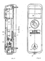
- 1 is a lower part fastened to the traffic light mast with screws 2 in a known manner
- 3 is the top which is suspended at the top with a nose 4 in an opening of the lower part and fastened from below by screws 5 and which is accordingly rotated by a pivoting movement AB an axis going through the nose 4 can be lifted off or placed on the lower part 1.
- the lower part 1 receives in a fitting in the opening 6 with strain relief only the end of the power supply cable and the buzzer 7, whose sound openings 8 emerge at the lower part rear 9, which therefore no longer give cause, with a suitable tool in the interior of the housing being able to penetrate in a damaging or destructive manner. It is true that the sound openings 8 emerging directly at the rear and thus at the mast must be in there over the Width of the housing extending, right-angled or oblique branches 8 'open so that the sound can penetrate to the outside, but through the thus created right-angled branching sound paths, no tools can be guided into the interior of the housing.
- the housing cover contains all the elements and devices required for the desired circuits and displays, e.g. the transformer 10, the rectifier 11, the time constant capacitors 12, the smoothing capacitor 13, resistors 14, for the "buzzer” assembly the precision timers 15, the signal generator 16 and the coupling capacitor 17, furthermore potentiometers 18, safety relays 19, the varistor 20, a vibrator, a microsafety device 21 and a so-called blind "overpass symbol” 22 indicating the direction of the overpass.
- the transformer 10 the rectifier 11, the time constant capacitors 12, the smoothing capacitor 13, resistors 14, for the "buzzer” assembly the precision timers 15, the signal generator 16 and the coupling capacitor 17, furthermore potentiometers 18, safety relays 19, the varistor 20, a vibrator, a microsafety device 21 and a so-called blind "overpass symbol” 22 indicating the direction of the overpass.
- the electrical connection between the supply cable introduced through the rear wall of the housing at 6 and the elements and devices accommodated in the cover is generally designated by 23.
- the end of the inserted cable is branched off and each branch is connected to a rectangular socket 25 in the front view, which has a rectangular opening 26 that is conductively connected to the power supply.
- the number of adjacent sockets 25 depends on the number of connections required. in the example shown, 6 sockets are assumed.
- the sockets 25 Corresponding to the sockets 25 are in the lid on a base 27 side by side electrically conductive to the individual elements and devices connected pins 28 mounted, which when connecting the cover 1 to the lower part 3 immerse in a current-connecting manner in the openings 26 and pull out of the cover when the cover is removed, ie, when applying the cover, a power connection between the supply cable and the individual elements and devices automatically and interrupt them automatically when the cover is removed.
- the height of the openings 26 is selected in accordance with the pivoting radius described by the pins 28 when the lid is being closed or opened, that is, these must be higher than the pins are thick in order to take into account that the pin ends when the lid is opened and closed describe an arc. Another possibility would be to make the openings smaller and to bend the pins according to the swivel radius.
- the vibrator is generally designated by 29, the vibrating stopper 30 of which extends with an extension 31 and directional arrow 32 from the bottom of the device box housing and can be felt as vibrating by the blind during the green phase.
- the invention therefore provides for a U-shaped bracket 33 which is adjustable in height and which influences the electromagnetic field and thus the vibration intensity and which in the example shown is adjustable in height by means of two screws 34 in elongated holes 35 of the bracket.
- the equipment box described above and shown in FIGS. 1 and 2 can be expanded by further switching options without becoming wider as a result become, for example, a box for a so-called “requirement or requirement light", for example a sensor to be operated from the outside or a push button, a sign saying "Please touch” and possibly also an LED or LCD display that lights up after switching on " Signal comes "provides.
- a box for a so-called “requirement or requirement light” for example a sensor to be operated from the outside or a push button, a sign saying "Please touch” and possibly also an LED or LCD display that lights up after switching on " Signal comes "provides.
- the design and equipment of the box can remain approximately up to the dash-dotted line T as shown in FIGS. 1 and 2 and the elements and devices which are additionally required can be accommodated in an attachable part.
- an injection mold for the lower part can be produced, which is the same in all versions, and the injection mold for the upper part can be placed on it shortly or longer, depending on the type.
Landscapes
- Physics & Mathematics (AREA)
- General Physics & Mathematics (AREA)
- Audible And Visible Signals (AREA)
- Traffic Control Systems (AREA)
Applications Claiming Priority (2)
| Application Number | Priority Date | Filing Date | Title |
|---|---|---|---|
| DE19893927636 DE3927636C1 (fr) | 1989-08-22 | 1989-08-22 | |
| DE3927636 | 1989-08-22 |
Publications (2)
| Publication Number | Publication Date |
|---|---|
| EP0414063A2 true EP0414063A2 (fr) | 1991-02-27 |
| EP0414063A3 EP0414063A3 (en) | 1992-12-02 |
Family
ID=6387584
Family Applications (1)
| Application Number | Title | Priority Date | Filing Date |
|---|---|---|---|
| EP19900115361 Withdrawn EP0414063A3 (en) | 1989-08-22 | 1990-08-10 | Apparatus casings for alternating signalling devices |
Country Status (2)
| Country | Link |
|---|---|
| EP (1) | EP0414063A3 (fr) |
| DE (1) | DE3927636C1 (fr) |
Cited By (1)
| Publication number | Priority date | Publication date | Assignee | Title |
|---|---|---|---|---|
| EP2131341A1 (fr) * | 2008-06-05 | 2009-12-09 | LIC Langmatz GmbH | Appareil de sollicitation pour un feu de circulation |
Families Citing this family (2)
| Publication number | Priority date | Publication date | Assignee | Title |
|---|---|---|---|---|
| RU2180139C1 (ru) * | 2000-06-28 | 2002-02-27 | Иванов Виктор Борисович | Светофор (варианты) |
| DE102009030159B4 (de) * | 2009-06-24 | 2012-04-19 | Langmatz Gmbh | Anforderungsgerät für eine Verkehrsampel |
Family Cites Families (7)
| Publication number | Priority date | Publication date | Assignee | Title |
|---|---|---|---|---|
| US2461448A (en) * | 1947-04-02 | 1949-02-08 | Smith Everett Manley | Street crossing signal device for blind pedestrians |
| DE1994310U (de) * | 1968-06-28 | 1968-09-19 | Aga Ab | Akustisches signalgeraet. |
| US3624269A (en) * | 1970-03-09 | 1971-11-30 | Veped Traffic Controls Inc | Column for supporting electrical devices embodying a handhole electrical terminal compartment near its base |
| US3999160A (en) * | 1975-12-05 | 1976-12-21 | Mcdonnell Richard M | Modular traffic signal apparatus |
| DE2816683A1 (de) * | 1978-04-18 | 1979-10-31 | Wolfgang Ipach | Akustische verkehrshilfe fuer blinde |
| DE3523526A1 (de) * | 1984-07-30 | 1986-02-06 | Celaya Emparanza y Galdos, S.A., Vitoria | Batterie fuer einen tragbaren verkehrssignalgeber |
| US4654745A (en) * | 1984-12-24 | 1987-03-31 | Corby Industries, Inc. | Electronic access control system for use with conventional switch plates and boxes |
-
1989
- 1989-08-22 DE DE19893927636 patent/DE3927636C1/de not_active Expired - Fee Related
-
1990
- 1990-08-10 EP EP19900115361 patent/EP0414063A3/de not_active Withdrawn
Cited By (1)
| Publication number | Priority date | Publication date | Assignee | Title |
|---|---|---|---|---|
| EP2131341A1 (fr) * | 2008-06-05 | 2009-12-09 | LIC Langmatz GmbH | Appareil de sollicitation pour un feu de circulation |
Also Published As
| Publication number | Publication date |
|---|---|
| EP0414063A3 (en) | 1992-12-02 |
| DE3927636C1 (fr) | 1990-11-29 |
Similar Documents
| Publication | Publication Date | Title |
|---|---|---|
| EP2911141A1 (fr) | Éclairage | |
| EP0414063A2 (fr) | Caissons pour appareil pour dispositifs de signalisation alternative | |
| DE29509073U1 (de) | Druckluftwartungsgerät | |
| EP1426143B1 (fr) | Dispositif de serrage, notamment dispositif de serrage à genouillère | |
| DE3336273A1 (de) | Sensoreinheit | |
| DE9316757U1 (de) | Pumpenstand mit einer Pumpe | |
| DE202021102115U1 (de) | Übungssystem zum Erlernen elektrischer Schaltungsanordnungen | |
| DE60009344T2 (de) | Elektromagnetisches relais | |
| DE2147068B2 (de) | Logischer schaltungsbaustein fuer lehrzwecke | |
| EP0432284B1 (fr) | Boîte de commande suspendue à boutons-poussoirs pour contrôler des appareils de levage et/ou des grues | |
| EP2270763B1 (fr) | Appareil de sollicitation pour un feu de circulation | |
| DE102005032409B4 (de) | Modulgehäuse mit Durchgangsverdrahtung | |
| DE19963118C1 (de) | Koppelvorrichtung | |
| DE10119456C1 (de) | Beschriftungsverfahren für ein elektrisches Gerät | |
| EP0910234A2 (fr) | Module fonctionnel d'un automate programmable avec panneau indicateur | |
| DE3713031A1 (de) | Wasserwaechter | |
| EP0448508A1 (fr) | Dispositif pour le découpage | |
| DE9108297U1 (de) | Adaptertafel für elektrische Installationseinrichtungen | |
| DE2714450A1 (de) | Lichtsignalgeber, vorzugsweise zur optischen anzeige bei selbsttaetigen brandmeldern | |
| DE29710415U1 (de) | Zentralelektrik für Sonderfahrzeuge | |
| DE29712392U1 (de) | Elektromagnetisches Schaltgerät mit busfähigem Verstärkerbaustein | |
| EP4080486A1 (fr) | Système d'exercices permettant d'étudier des ensembles circuits électriques | |
| DE202022106080U1 (de) | Optische Signalvorrichtung und vernetztes System umfassend eine solche optische Signalvorrichtung | |
| DE3609720C2 (fr) | ||
| EP0470947A1 (fr) | Feu de signalisation |
Legal Events
| Date | Code | Title | Description |
|---|---|---|---|
| PUAI | Public reference made under article 153(3) epc to a published international application that has entered the european phase |
Free format text: ORIGINAL CODE: 0009012 |
|
| AK | Designated contracting states |
Kind code of ref document: A2 Designated state(s): AT BE CH ES FR IT LI LU NL |
|
| PUAL | Search report despatched |
Free format text: ORIGINAL CODE: 0009013 |
|
| AK | Designated contracting states |
Kind code of ref document: A3 Designated state(s): AT BE CH ES FR IT LI LU NL |
|
| STAA | Information on the status of an ep patent application or granted ep patent |
Free format text: STATUS: THE APPLICATION IS DEEMED TO BE WITHDRAWN |
|
| 18D | Application deemed to be withdrawn |
Effective date: 19930301 |