EP1426143B1 - Dispositif de serrage, notamment dispositif de serrage à genouillère - Google Patents
Dispositif de serrage, notamment dispositif de serrage à genouillère Download PDFInfo
- Publication number
- EP1426143B1 EP1426143B1 EP03018177A EP03018177A EP1426143B1 EP 1426143 B1 EP1426143 B1 EP 1426143B1 EP 03018177 A EP03018177 A EP 03018177A EP 03018177 A EP03018177 A EP 03018177A EP 1426143 B1 EP1426143 B1 EP 1426143B1
- Authority
- EP
- European Patent Office
- Prior art keywords
- clamping device
- plug
- headpiece
- sensor
- halves
- Prior art date
- Legal status (The legal status is an assumption and is not a legal conclusion. Google has not performed a legal analysis and makes no representation as to the accuracy of the status listed.)
- Expired - Lifetime
Links
- 230000005540 biological transmission Effects 0.000 claims description 10
- 230000001939 inductive effect Effects 0.000 claims description 6
- 238000005259 measurement Methods 0.000 claims description 3
- 238000002789 length control Methods 0.000 claims 1
- 238000000926 separation method Methods 0.000 claims 1
- 238000012546 transfer Methods 0.000 abstract description 2
- 238000003780 insertion Methods 0.000 description 4
- 230000037431 insertion Effects 0.000 description 4
- 230000008054 signal transmission Effects 0.000 description 4
- 238000004519 manufacturing process Methods 0.000 description 3
- 230000001419 dependent effect Effects 0.000 description 2
- 238000013461 design Methods 0.000 description 2
- 238000011161 development Methods 0.000 description 2
- 230000018109 developmental process Effects 0.000 description 2
- 238000004891 communication Methods 0.000 description 1
- 230000006698 induction Effects 0.000 description 1
- 238000009434 installation Methods 0.000 description 1
- 238000012423 maintenance Methods 0.000 description 1
- 238000013507 mapping Methods 0.000 description 1
Images

Classifications
-
- B—PERFORMING OPERATIONS; TRANSPORTING
- B25—HAND TOOLS; PORTABLE POWER-DRIVEN TOOLS; MANIPULATORS
- B25B—TOOLS OR BENCH DEVICES NOT OTHERWISE PROVIDED FOR, FOR FASTENING, CONNECTING, DISENGAGING OR HOLDING
- B25B5/00—Clamps
- B25B5/16—Details, e.g. jaws, jaw attachments
-
- B—PERFORMING OPERATIONS; TRANSPORTING
- B25—HAND TOOLS; PORTABLE POWER-DRIVEN TOOLS; MANIPULATORS
- B25B—TOOLS OR BENCH DEVICES NOT OTHERWISE PROVIDED FOR, FOR FASTENING, CONNECTING, DISENGAGING OR HOLDING
- B25B5/00—Clamps
- B25B5/06—Arrangements for positively actuating jaws
- B25B5/12—Arrangements for positively actuating jaws using toggle links
- B25B5/122—Arrangements for positively actuating jaws using toggle links with fluid drive
Definitions
- the invention relates to a clamping device, in particular toggle lever clamping device, according to the preamble of claim 1, which is known from the document DE 297 18 644 A is known.
- a clamping device of a special kind as this is the opening angle size caused by length adjustment of the linearly movable actuator, resulting in that arranged in the end piece End thoroughlysabfragesensoren, as they may be designed in detail, not be installed variable position in the head
- the interrogation sensors do not have to be accessible from the outside, but, as far as is known and for whatever reason, this has not been practiced so far.
- the invention has for its object to remedy this, ie, jigs regarding their End einsabfrage wornen to improve and to design that always unavoidable re-occurring exchange requirements, these are not only reduced to the necessary minimum but can also be carried out quickly and easily.
- the solution according to the invention makes use, on the one hand, of the fact or knowledge that, in the case of tensioning devices with a variable-length actuator, the elements for the end position query no longer have to be installed on the head end to be accessible, ie, completely protected without further ado be placed in the head piece, and on the other hand, that particularly vulnerable male connector part or the elements for signal forwarding from the elements for End einsabfrage one hand to keep separate and easily removable forrecter Dunisse to attach the head and on the other hand to ensure that despite a separate holding a Signal transmission and power supply of the interrogator is guaranteed.
- a special feature is that on the one hand, the contactless energy transmission via interface for two to three sensors is sufficient, but on the other hand there are tensioning devices in which a continuous and higher energy-demanding path measurement takes place.
- tensioning devices in which a continuous and higher energy-demanding path measurement takes place.
- such a higher energy transfer is, as far as known, not possible with the resources available so far.
- the interface halves are designed as a plug and plug receptacle, the plug-in contacts of the plug with its side load easily separable respect. their insertion length are short.
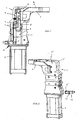
- the clamping device is made by reference to Fig.1 as before from a arranged in a tensioning head piece 1 adjusting mechanism 2 with a linearly adjustable by a drive 3, provided with position transmitter 4 and adjustable in length actuator 5, which is in communication with a clamping arm 6, wherein in the travel of the position sensor 4 at least one sensor. 7 arranged to detect at least one end position of the clamping arm 6 and equipped with elements 8 for passing the at least one end position signal.
- Fig.1 there is the guided linearly in the head piece 1 actuator 5, for example, from two mutually toothed in different positions parts T, T '. Depending on the toothing position of these parts T, T 'results in a more or less large opening angle ⁇ for the tensioning arm 6.
- T ' Results in a more or less large opening angle ⁇ for the tensioning arm 6.
- an embodiment is preferred in that the one sensor 7 and another sensor 7 'in linear distanced , Stationary assignment in the form of the already mentioned cassette 11 in the head piece 1 along the Geberstellweges inside the head piece 1 are arranged.
- the head piece 1 is formed in a known manner from two halves 1 ', 1 ", wherein the cassette 11 is arranged in one of the halves which are substantially cup-shaped, such a protected installation of the cassette also applies to the case where the head piece 1 is fork-shaped should be, which is also common in such fixtures.
- interface halves 9,9 ' are preferably in the form of inductive current and signal transformers, since in this way not only a signal transmission to the connector terminal 10 can take place, but vice versa from there also a power supply Sensors 7,7 'itself, which is a prerequisite that even query signals generated and can be passed.
- the signal transmission can also be done optically.
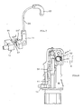
- Fig.2 referenced which shows the cassette 11 separate plug connector part 10 with its interface half 9 'in the insertion position.
- the plug connection part 10 is provided with a fastened to the outside of the head piece 1 holding extension 14.
- FIG. 6 Apart from such a mapping of the interfaces halves 9,9 'but they can also reference Figure 6 be associated under interposition of an inductive transmission element 12 operatively connected to each other, if this should require special design conditions on the device itself or their arrangement conditions at the site.
- a concrete embodiment in this respect shows the above Figure 6 according to which the inductive transmission element 12 passes through the wall 1 'of the head piece 1 and engages contactlessly with its ends projecting out of the wall 1' into the respective interface half 9, 9 'or its induction coils 15.
- the plug-side connector 10, which is not particularly shown here, which contains a coil 15, is also fastened access-accessible on the outside of the head piece 1 detachably with one or two small screws.
- the plug 90 and the plug receptacle 90' are provided outside the power supply in a suitable manner with Verrastungs instituten, the on the one hand support the cohesion of said elements, on the other hand, but easily solve each other in a side load.
- Such latching elements can be formed, for example, from at least one small, dome-like depression on one element and a small nubs can be latched therein on the other element, which is not particularly illustrated, as readily conceivable.
Landscapes
- Engineering & Computer Science (AREA)
- Mechanical Engineering (AREA)
- Jigs For Machine Tools (AREA)
- Details Of Connecting Devices For Male And Female Coupling (AREA)
- Gripping Jigs, Holding Jigs, And Positioning Jigs (AREA)
- Arrangements For Transmission Of Measured Signals (AREA)
- Mechanically-Actuated Valves (AREA)
- Moulds For Moulding Plastics Or The Like (AREA)
Claims (10)
- Dispositif de serrage, en particulier dispositif de serrage à genouillère, constitué d'une mécanique de commande (2) installée dans une tête de serrage (1), avec un organe de commande (5), qui est réglable dans la longueur, déplaçable linéairement à l'aide d'un entraînement (3) et pourvu d'un transmetteur de position (4), tout en étant relié à un bras de serrage (4), au moins un détecteur (7) destiné à la détection d'au moins une position finale du bras de serrage (6) étant installé sur le parcours de déplacement du transmetteur de position (4) et équipé d'éléments (8) destinés à la la retransmission de l'au moins un signal de position finale,
caractérisé en ce que
l'au moins un détecteur (7) et les éléments (8) destinés à la retransmission de l'au moins un signal de position finale est monté sur ou dans la tête de serrage (1), en tant que pièces séparées, tout en étant chacun pourvu d'une moitié d'accouplement (9, 9') et attribués de telle manière l'un à l'autre dans la tête (1), que les moitiés d'accouplement (9, 9') forment une liaison fonctionnelle pour une transmission sans contact de l'au moins un signal de position finale, les éléments (8) destinés à la retransmission de l'au moins un signal de position finale étant montés à portée de la main et fixés de façon amovible sur une pièce de connexion (10) située sur la tête (1). - Dispositif de serrage selon la revendication 1,
caractérisé en ce que
ledit détecteur (7) ainsi qu'un détecteur supplémentaire (7') sont installés de façon stationnaire et linéairement espacés l'un de l'autre, en forme de cassette (11), le long du parcours du transmetteur de position à l'intérieur de la tête (1). - Dispositif de serrage selon la revendication 2,
caractérisé en ce que
la tête (1) est constituée de deux moitiés (1', 1") et en ce que la cassette (11) est installée dans l'une des moitiés. - Dispositif de serrage selon l'une des revendications 1 à 3,
caractérisé en ce que
les moitiés d'accouplement (9, 9') sont conçues sous la forme d'organes de transmission de signaux ou de courant inductifs. - Dispositif de serrage selon la revendication 4,
caractérisé en ce que
les moitiés d'accouplement (9, 9') sont attribuées l'une à l'autre sous la forme d'une liaison fonctionnelle, par l'intermédiaire d'un élément de transmission inductif (12). - Dispositif de serrage selon la revendication 5,
caractérisé en ce que
l'élément de transmission inductif (12) traverse la paroi (1') de la tête (1) et s'engage sans contact dans chacune des moitiés d'accouplement (9, 9') par ses extrémités sortant de la paroi (1'). - Dispositif de serrage selon l'une des revendications 2 à 4,
caractérisé en ce que
les moitiés d'accouplement (9, 9') sont disposées dans des prolongements (13, 13') du genre languette de la cassette (11) et de la pièce de connexion (10), le prolongement (13) de la pièce de connexion (10) sur la tête (1) étant conçu de manière à pouvoir être enfoncé dans la tête, en affleurement avec le prolongement (13') de la cassette (11). - Dispositif de serrage selon la revendication 7,
caractérisé en ce que
la pièce de connexion (10) est pourvue d'un prolongement de maintien (14) apte à être fixé extérieurement sur la tête (1). - Dispositif de serrage selon l'une des revendications 1 à 8, avec un détecteur (7') nécessitant une transmission d'énergie plus élevée pour le mesurage de parcours en continu,
caractérisé en ce que
les moitiés d'accouplement (9, 9') sont conçues comme un connecteur mâle (90) et une prise femelle (90'), les contacts d'enfichage (91) du connecteur mâle (90) présentant des dimensions courtes, avec une longueur d'enfichage (L) de 3 à 5 mm, pour faciliter la mise hors contact. - Dispositif de serrage selon la revendication 9,
caractérisé en ce que
le connecteur mâle (90) et la prise femelle (90') sont pourvus d'éléments d'enclenchement permettant de renforcer davantage leur maintien, mais néanmoins faciles à ôter, à l'extérieur des lignes de courant.
Applications Claiming Priority (2)
| Application Number | Priority Date | Filing Date | Title |
|---|---|---|---|
| DE10256385 | 2002-12-02 | ||
| DE10256385A DE10256385B3 (de) | 2002-12-02 | 2002-12-02 | Spannvorrichtung, insbesondere Kniehebelspannvorrichtung |
Publications (3)
| Publication Number | Publication Date |
|---|---|
| EP1426143A2 EP1426143A2 (fr) | 2004-06-09 |
| EP1426143A3 EP1426143A3 (fr) | 2007-08-15 |
| EP1426143B1 true EP1426143B1 (fr) | 2009-04-15 |
Family
ID=30775619
Family Applications (1)
| Application Number | Title | Priority Date | Filing Date |
|---|---|---|---|
| EP03018177A Expired - Lifetime EP1426143B1 (fr) | 2002-12-02 | 2003-08-09 | Dispositif de serrage, notamment dispositif de serrage à genouillère |
Country Status (5)
| Country | Link |
|---|---|
| EP (1) | EP1426143B1 (fr) |
| AT (1) | ATE428540T1 (fr) |
| DE (2) | DE10256385B3 (fr) |
| ES (1) | ES2321592T3 (fr) |
| PT (1) | PT1426143E (fr) |
Cited By (1)
| Publication number | Priority date | Publication date | Assignee | Title |
|---|---|---|---|---|
| CN105313040A (zh) * | 2014-08-01 | 2016-02-10 | 佩佩尔+富克斯有限公司 | 用于肘形杆张紧装置的查问单元 |
Families Citing this family (7)
| Publication number | Priority date | Publication date | Assignee | Title |
|---|---|---|---|---|
| ITMI20061226A1 (it) * | 2006-06-26 | 2007-12-27 | Univer Spa | Dispositivo per il bloccaggio e-o la centragtuira di pezzi da lavorare con posizioni operative settabili manualmente |
| DE102009054153A1 (de) | 2009-11-23 | 2011-05-26 | De-Sta-Co Europe Gmbh | Spannvorrichtung |
| DE102010046188A1 (de) | 2010-09-23 | 2012-03-29 | De-Sta-Co Europe Gmbh | Betätigungsvorrichtung |
| EP2433750B1 (fr) | 2010-09-23 | 2013-04-10 | DE-STA-CO Europe GmbH | Dispositif d'actionnement |
| DE102011107397A1 (de) | 2011-07-07 | 2013-01-10 | De-Sta-Co Europe Gmbh | Betätigungsvorrichtung |
| DE102013001004B3 (de) * | 2013-01-22 | 2014-02-06 | Tünkers Maschinenbau Gmbh | Vorrichtung zum Spannen, Prägen, Schweißen, Clinchen oder Schwenken von Bauteilen, mit einer Sensorvorrichtung zur Positionsbestimmung eines länglichen Verstellteils, welches mit einem Kniehebelgelenk ein schwenkbares Vorrichtungsteil antreibt |
| FR3027387B1 (fr) | 2014-10-16 | 2018-02-16 | Senstronic | Dispositif detecteur a constitution modulaire et equipement industriel le comportant |
Family Cites Families (3)
| Publication number | Priority date | Publication date | Assignee | Title |
|---|---|---|---|---|
| DE29718644U1 (de) * | 1997-10-21 | 1997-12-11 | Tünkers Maschinenbau GmbH, 40880 Ratingen | Abfragekassette |
| DE20004977U1 (de) * | 2000-03-17 | 2000-07-13 | Festo AG & Co, 73734 Esslingen | Kopfstück einer Spannvorrichtung |
| DE20209237U1 (de) * | 2002-06-13 | 2002-09-19 | DE-STA-Co Metallerzeugnisse GmbH, 61440 Oberursel | Kniehebelspannvorrichtung |
-
2002
- 2002-12-02 DE DE10256385A patent/DE10256385B3/de not_active Expired - Fee Related
-
2003
- 2003-08-09 PT PT03018177T patent/PT1426143E/pt unknown
- 2003-08-09 ES ES03018177T patent/ES2321592T3/es not_active Expired - Lifetime
- 2003-08-09 EP EP03018177A patent/EP1426143B1/fr not_active Expired - Lifetime
- 2003-08-09 DE DE50311413T patent/DE50311413D1/de not_active Expired - Lifetime
- 2003-08-09 AT AT03018177T patent/ATE428540T1/de not_active IP Right Cessation
Cited By (2)
| Publication number | Priority date | Publication date | Assignee | Title |
|---|---|---|---|---|
| CN105313040A (zh) * | 2014-08-01 | 2016-02-10 | 佩佩尔+富克斯有限公司 | 用于肘形杆张紧装置的查问单元 |
| US10710205B2 (en) | 2014-08-01 | 2020-07-14 | Pepperl+Fuchs Gmbh | Query unit for toggle lever clamp |
Also Published As
| Publication number | Publication date |
|---|---|
| PT1426143E (pt) | 2009-06-04 |
| DE50311413D1 (de) | 2009-05-28 |
| EP1426143A3 (fr) | 2007-08-15 |
| ATE428540T1 (de) | 2009-05-15 |
| ES2321592T3 (es) | 2009-06-09 |
| EP1426143A2 (fr) | 2004-06-09 |
| DE10256385B3 (de) | 2004-02-26 |
Similar Documents
| Publication | Publication Date | Title |
|---|---|---|
| EP0616236B1 (fr) | Connecteur pour un guide d'ondes optique | |
| EP0226532B1 (fr) | Cellule de commutation électrique avec une commande de déplacement pour un appareil de commutation mobile | |
| EP1862767A2 (fr) | Capteur de position de sécurité pour cylindre, cylindre doté d'un tel capteur de position | |
| EP3763882A1 (fr) | Dispositif de changement rapide | |
| DE3917242A1 (de) | Magnetventilbatterie | |
| EP1426143B1 (fr) | Dispositif de serrage, notamment dispositif de serrage à genouillère | |
| EP0292743A1 (fr) | Ferme-porte avec dispositif indicateur de la force de fermeture | |
| WO2005067145A1 (fr) | Interrupteur de securite servant a surveiller une position de fermeture de deux pieces mobiles l'une par rapport a l'autre | |
| EP0316590A2 (fr) | Fermeture pour porte à commande électronique et serrure cylindrique | |
| DE8908288U1 (de) | Kniehebelspannvorrichtung für den Karosseriebau | |
| EP0439063A2 (fr) | Moyen de serrage | |
| EP1351041B1 (fr) | Balance avec une protection contre le vent | |
| EP1921242A1 (fr) | Dispositif d'actionnement pour pièces mobiles de bâtiment, en particulier fenêtres ou trappes basculantes | |
| DE8621671U1 (de) | Wechselvorrichtung | |
| DE102007020313B4 (de) | Vorrichtung zum Überwachen des Zustandes einer Schutzeinrichtung einer Maschine | |
| EP0930130A2 (fr) | Dispositif de serrage | |
| DE20103739U1 (de) | Elektrisches Installationsgerät | |
| DE4318125B4 (de) | Hohlkörper für die elektrische Installation | |
| DE102008046179A1 (de) | Optoelektronischer Sensor und Verfahren zum Anbringen | |
| DE202010015812U1 (de) | Haftmagneteinrichtung | |
| DE19917211C1 (de) | Vorrichtung zum Schalten einer Verbindung in Abhängigkeit des Zustandes einer zu überwachenden Einrichtung, insbesondere Sicherheitsschalter | |
| DE8632990U1 (de) | Berührungsloser Sensor | |
| DE10210635B4 (de) | Explosionsgeschütztes Gehäuse mit modularem Vorsatzgehäuse | |
| DE102016108612A1 (de) | Bolzenschweißpistole | |
| DE3406410A1 (de) | Hydraulischer tuerschliesser mit oeffnungswinkel-signalisierung |
Legal Events
| Date | Code | Title | Description |
|---|---|---|---|
| PUAI | Public reference made under article 153(3) epc to a published international application that has entered the european phase |
Free format text: ORIGINAL CODE: 0009012 |
|
| AK | Designated contracting states |
Kind code of ref document: A2 Designated state(s): AT BE BG CH CY CZ DE DK EE ES FI FR GB GR HU IE IT LI LU MC NL PT RO SE SI SK TR |
|
| AX | Request for extension of the european patent |
Extension state: AL LT LV MK |
|
| RAP1 | Party data changed (applicant data changed or rights of an application transferred) |
Owner name: DE-STA-CO EUROPE GMBH |
|
| PUAL | Search report despatched |
Free format text: ORIGINAL CODE: 0009013 |
|
| AK | Designated contracting states |
Kind code of ref document: A3 Designated state(s): AT BE BG CH CY CZ DE DK EE ES FI FR GB GR HU IE IT LI LU MC NL PT RO SE SI SK TR |
|
| AX | Request for extension of the european patent |
Extension state: AL LT LV MK |
|
| 17P | Request for examination filed |
Effective date: 20071205 |
|
| AKX | Designation fees paid |
Designated state(s): AT BE BG CH CY CZ DE DK EE ES FI FR GB GR HU IE IT LI LU MC NL PT RO SE SI SK TR |
|
| GRAP | Despatch of communication of intention to grant a patent |
Free format text: ORIGINAL CODE: EPIDOSNIGR1 |
|
| GRAS | Grant fee paid |
Free format text: ORIGINAL CODE: EPIDOSNIGR3 |
|
| GRAA | (expected) grant |
Free format text: ORIGINAL CODE: 0009210 |
|
| AK | Designated contracting states |
Kind code of ref document: B1 Designated state(s): AT BE BG CH CY CZ DE DK EE ES FI FR GB GR HU IE IT LI LU MC NL PT RO SE SI SK TR |
|
| REG | Reference to a national code |
Ref country code: CH Ref legal event code: EP Ref country code: GB Ref legal event code: FG4D Free format text: NOT ENGLISH |
|
| REG | Reference to a national code |
Ref country code: IE Ref legal event code: FG4D |
|
| REF | Corresponds to: |
Ref document number: 50311413 Country of ref document: DE Date of ref document: 20090528 Kind code of ref document: P |
|
| REG | Reference to a national code |
Ref country code: PT Ref legal event code: SC4A Free format text: AVAILABILITY OF NATIONAL TRANSLATION Effective date: 20090528 |
|
| REG | Reference to a national code |
Ref country code: ES Ref legal event code: FG2A Ref document number: 2321592 Country of ref document: ES Kind code of ref document: T3 |
|
| REG | Reference to a national code |
Ref country code: SE Ref legal event code: TRGR |
|
| NLV1 | Nl: lapsed or annulled due to failure to fulfill the requirements of art. 29p and 29m of the patents act | ||
| PG25 | Lapsed in a contracting state [announced via postgrant information from national office to epo] |
Ref country code: NL Free format text: LAPSE BECAUSE OF FAILURE TO SUBMIT A TRANSLATION OF THE DESCRIPTION OR TO PAY THE FEE WITHIN THE PRESCRIBED TIME-LIMIT Effective date: 20090415 Ref country code: SI Free format text: LAPSE BECAUSE OF FAILURE TO SUBMIT A TRANSLATION OF THE DESCRIPTION OR TO PAY THE FEE WITHIN THE PRESCRIBED TIME-LIMIT Effective date: 20090415 |
|
| REG | Reference to a national code |
Ref country code: IE Ref legal event code: FD4D |
|
| PG25 | Lapsed in a contracting state [announced via postgrant information from national office to epo] |
Ref country code: DK Free format text: LAPSE BECAUSE OF FAILURE TO SUBMIT A TRANSLATION OF THE DESCRIPTION OR TO PAY THE FEE WITHIN THE PRESCRIBED TIME-LIMIT Effective date: 20090415 Ref country code: RO Free format text: LAPSE BECAUSE OF FAILURE TO SUBMIT A TRANSLATION OF THE DESCRIPTION OR TO PAY THE FEE WITHIN THE PRESCRIBED TIME-LIMIT Effective date: 20090415 Ref country code: EE Free format text: LAPSE BECAUSE OF FAILURE TO SUBMIT A TRANSLATION OF THE DESCRIPTION OR TO PAY THE FEE WITHIN THE PRESCRIBED TIME-LIMIT Effective date: 20090415 Ref country code: IE Free format text: LAPSE BECAUSE OF FAILURE TO SUBMIT A TRANSLATION OF THE DESCRIPTION OR TO PAY THE FEE WITHIN THE PRESCRIBED TIME-LIMIT Effective date: 20090415 |
|
| PLBE | No opposition filed within time limit |
Free format text: ORIGINAL CODE: 0009261 |
|
| STAA | Information on the status of an ep patent application or granted ep patent |
Free format text: STATUS: NO OPPOSITION FILED WITHIN TIME LIMIT |
|
| PG25 | Lapsed in a contracting state [announced via postgrant information from national office to epo] |
Ref country code: SK Free format text: LAPSE BECAUSE OF FAILURE TO SUBMIT A TRANSLATION OF THE DESCRIPTION OR TO PAY THE FEE WITHIN THE PRESCRIBED TIME-LIMIT Effective date: 20090415 |
|
| 26N | No opposition filed |
Effective date: 20100118 |
|
| PG25 | Lapsed in a contracting state [announced via postgrant information from national office to epo] |
Ref country code: BG Free format text: LAPSE BECAUSE OF FAILURE TO SUBMIT A TRANSLATION OF THE DESCRIPTION OR TO PAY THE FEE WITHIN THE PRESCRIBED TIME-LIMIT Effective date: 20090715 Ref country code: MC Free format text: LAPSE BECAUSE OF NON-PAYMENT OF DUE FEES Effective date: 20090831 |
|
| REG | Reference to a national code |
Ref country code: CH Ref legal event code: PL |
|
| PG25 | Lapsed in a contracting state [announced via postgrant information from national office to epo] |
Ref country code: CH Free format text: LAPSE BECAUSE OF NON-PAYMENT OF DUE FEES Effective date: 20090831 Ref country code: LI Free format text: LAPSE BECAUSE OF NON-PAYMENT OF DUE FEES Effective date: 20090831 |
|
| PG25 | Lapsed in a contracting state [announced via postgrant information from national office to epo] |
Ref country code: GR Free format text: LAPSE BECAUSE OF FAILURE TO SUBMIT A TRANSLATION OF THE DESCRIPTION OR TO PAY THE FEE WITHIN THE PRESCRIBED TIME-LIMIT Effective date: 20090716 |
|
| PG25 | Lapsed in a contracting state [announced via postgrant information from national office to epo] |
Ref country code: AT Free format text: LAPSE BECAUSE OF NON-PAYMENT OF DUE FEES Effective date: 20090809 |
|
| PG25 | Lapsed in a contracting state [announced via postgrant information from national office to epo] |
Ref country code: IT Free format text: LAPSE BECAUSE OF FAILURE TO SUBMIT A TRANSLATION OF THE DESCRIPTION OR TO PAY THE FEE WITHIN THE PRESCRIBED TIME-LIMIT Effective date: 20090415 |
|
| PG25 | Lapsed in a contracting state [announced via postgrant information from national office to epo] |
Ref country code: LU Free format text: LAPSE BECAUSE OF NON-PAYMENT OF DUE FEES Effective date: 20090809 |
|
| PG25 | Lapsed in a contracting state [announced via postgrant information from national office to epo] |
Ref country code: HU Free format text: LAPSE BECAUSE OF FAILURE TO SUBMIT A TRANSLATION OF THE DESCRIPTION OR TO PAY THE FEE WITHIN THE PRESCRIBED TIME-LIMIT Effective date: 20091016 |
|
| PG25 | Lapsed in a contracting state [announced via postgrant information from national office to epo] |
Ref country code: TR Free format text: LAPSE BECAUSE OF FAILURE TO SUBMIT A TRANSLATION OF THE DESCRIPTION OR TO PAY THE FEE WITHIN THE PRESCRIBED TIME-LIMIT Effective date: 20090415 |
|
| PG25 | Lapsed in a contracting state [announced via postgrant information from national office to epo] |
Ref country code: CY Free format text: LAPSE BECAUSE OF FAILURE TO SUBMIT A TRANSLATION OF THE DESCRIPTION OR TO PAY THE FEE WITHIN THE PRESCRIBED TIME-LIMIT Effective date: 20090415 |
|
| REG | Reference to a national code |
Ref country code: FR Ref legal event code: PLFP Year of fee payment: 13 |
|
| PGFP | Annual fee paid to national office [announced via postgrant information from national office to epo] |
Ref country code: FI Payment date: 20150819 Year of fee payment: 13 Ref country code: CZ Payment date: 20150805 Year of fee payment: 13 Ref country code: ES Payment date: 20150720 Year of fee payment: 13 Ref country code: GB Payment date: 20150818 Year of fee payment: 13 Ref country code: PT Payment date: 20150717 Year of fee payment: 13 Ref country code: DE Payment date: 20150717 Year of fee payment: 13 |
|
| PGFP | Annual fee paid to national office [announced via postgrant information from national office to epo] |
Ref country code: FR Payment date: 20150831 Year of fee payment: 13 Ref country code: SE Payment date: 20150818 Year of fee payment: 13 Ref country code: BE Payment date: 20150728 Year of fee payment: 13 |
|
| PG25 | Lapsed in a contracting state [announced via postgrant information from national office to epo] |
Ref country code: BE Free format text: LAPSE BECAUSE OF NON-PAYMENT OF DUE FEES Effective date: 20160831 |
|
| REG | Reference to a national code |
Ref country code: DE Ref legal event code: R119 Ref document number: 50311413 Country of ref document: DE |
|
| REG | Reference to a national code |
Ref country code: SE Ref legal event code: EUG |
|
| GBPC | Gb: european patent ceased through non-payment of renewal fee |
Effective date: 20160809 |
|
| PG25 | Lapsed in a contracting state [announced via postgrant information from national office to epo] |
Ref country code: SE Free format text: LAPSE BECAUSE OF NON-PAYMENT OF DUE FEES Effective date: 20160810 Ref country code: FI Free format text: LAPSE BECAUSE OF NON-PAYMENT OF DUE FEES Effective date: 20160809 |
|
| REG | Reference to a national code |
Ref country code: FR Ref legal event code: ST Effective date: 20170428 |
|
| PG25 | Lapsed in a contracting state [announced via postgrant information from national office to epo] |
Ref country code: PT Free format text: LAPSE BECAUSE OF NON-PAYMENT OF DUE FEES Effective date: 20170209 Ref country code: CZ Free format text: LAPSE BECAUSE OF NON-PAYMENT OF DUE FEES Effective date: 20160809 |
|
| PG25 | Lapsed in a contracting state [announced via postgrant information from national office to epo] |
Ref country code: FR Free format text: LAPSE BECAUSE OF NON-PAYMENT OF DUE FEES Effective date: 20160831 Ref country code: GB Free format text: LAPSE BECAUSE OF NON-PAYMENT OF DUE FEES Effective date: 20160809 Ref country code: DE Free format text: LAPSE BECAUSE OF NON-PAYMENT OF DUE FEES Effective date: 20170301 |
|
| REG | Reference to a national code |
Ref country code: ES Ref legal event code: FD2A Effective date: 20180507 |
|
| PG25 | Lapsed in a contracting state [announced via postgrant information from national office to epo] |
Ref country code: ES Free format text: LAPSE BECAUSE OF NON-PAYMENT OF DUE FEES Effective date: 20160810 |