EP0414341B1 - Siebvorrichtung - Google Patents
Siebvorrichtung Download PDFInfo
- Publication number
- EP0414341B1 EP0414341B1 EP90305670A EP90305670A EP0414341B1 EP 0414341 B1 EP0414341 B1 EP 0414341B1 EP 90305670 A EP90305670 A EP 90305670A EP 90305670 A EP90305670 A EP 90305670A EP 0414341 B1 EP0414341 B1 EP 0414341B1
- Authority
- EP
- European Patent Office
- Prior art keywords
- discs
- shaft
- shafts
- liquid material
- solid matter
- Prior art date
- Legal status (The legal status is an assumption and is not a legal conclusion. Google has not performed a legal analysis and makes no representation as to the accuracy of the status listed.)
- Expired - Lifetime
Links
- 238000012216 screening Methods 0.000 title claims abstract description 22
- 239000007787 solid Substances 0.000 claims abstract description 27
- 239000011344 liquid material Substances 0.000 claims abstract description 18
- 239000010865 sewage Substances 0.000 claims abstract description 13
- 239000007788 liquid Substances 0.000 claims description 14
- 239000000463 material Substances 0.000 claims description 7
- 230000002879 macerating effect Effects 0.000 claims description 4
- 230000015556 catabolic process Effects 0.000 claims description 3
- 238000006731 degradation reaction Methods 0.000 claims description 3
- 238000000034 method Methods 0.000 claims description 3
- 239000010801 sewage sludge Substances 0.000 claims 1
- XLYOFNOQVPJJNP-UHFFFAOYSA-N water Substances O XLYOFNOQVPJJNP-UHFFFAOYSA-N 0.000 description 4
- 239000004033 plastic Substances 0.000 description 2
- 241000251468 Actinopterygii Species 0.000 description 1
- 230000004888 barrier function Effects 0.000 description 1
- 238000006073 displacement reaction Methods 0.000 description 1
- 230000000717 retained effect Effects 0.000 description 1
- 239000011343 solid material Substances 0.000 description 1
- 239000007921 spray Substances 0.000 description 1
- 238000010561 standard procedure Methods 0.000 description 1
- 239000002699 waste material Substances 0.000 description 1
Images
Classifications
-
- B—PERFORMING OPERATIONS; TRANSPORTING
- B01—PHYSICAL OR CHEMICAL PROCESSES OR APPARATUS IN GENERAL
- B01D—SEPARATION
- B01D33/00—Filters with filtering elements which move during the filtering operation
- B01D33/27—Filters with filtering elements which move during the filtering operation with rotary filtering surfaces, which are neither cylindrical nor planar, e.g. helical surfaces
- B01D33/275—Filters with filtering elements which move during the filtering operation with rotary filtering surfaces, which are neither cylindrical nor planar, e.g. helical surfaces using contiguous impervious surfaces
-
- B—PERFORMING OPERATIONS; TRANSPORTING
- B01—PHYSICAL OR CHEMICAL PROCESSES OR APPARATUS IN GENERAL
- B01D—SEPARATION
- B01D33/00—Filters with filtering elements which move during the filtering operation
- B01D33/44—Regenerating the filter material in the filter
- B01D33/46—Regenerating the filter material in the filter by scrapers, brushes nozzles or the like acting on the cake-side of the filtering element
- B01D33/466—Regenerating the filter material in the filter by scrapers, brushes nozzles or the like acting on the cake-side of the filtering element scrapers
-
- B—PERFORMING OPERATIONS; TRANSPORTING
- B01—PHYSICAL OR CHEMICAL PROCESSES OR APPARATUS IN GENERAL
- B01D—SEPARATION
- B01D33/00—Filters with filtering elements which move during the filtering operation
- B01D33/58—Handling the filter cake in the filter for purposes other than for regenerating the filter cake remaining on the filtering element
-
- B—PERFORMING OPERATIONS; TRANSPORTING
- B01—PHYSICAL OR CHEMICAL PROCESSES OR APPARATUS IN GENERAL
- B01D—SEPARATION
- B01D33/00—Filters with filtering elements which move during the filtering operation
- B01D33/70—Filters with filtering elements which move during the filtering operation having feed or discharge devices
- B01D33/76—Filters with filtering elements which move during the filtering operation having feed or discharge devices for discharging the filter cake, e.g. chutes
Definitions
- the present invention relates to the screening of liquid material having solid matter suspended in it, in particular to the screening of sewage waste.
- the standard method used to separate solid matter from the liquid material is to provide a belt screen which consists of a wire mesh passing continuously around two rollers like a conveyor belt.
- the belt screen may be arranged at an angle from the vertical, with the belt moving in an upwardly direction relative to the liquid flow, such that the liquid has to pass through the wire mesh screen twice.
- Added disadvantages are the tendency of the wire mesh to clog up and further impede the liquid flow, and the fact that the individual wires of the mesh are prone to deform upon impact by large solids.
- DE-A-3617665 discloses a screening system suitable for screening water having solid matter suspended in it or floating in it, including fish, which comprises a feed channel for the liquid material, a screening device located in the channel and including a number of sets of generally planar discs having parallel flat faces, the discs of each set being mounted on a horizontal shaft, and separated from one another axially, the shafts being mounted to extend on parallel horizontal axes, the discs of adjacent shafts being interleaved with one another, and means to cause the shafts to rotate independently in the same rotational sense such that successive shafts rotate progressively faster, wherein the discs of each set are rigidly mounted on their associated shaft with the faces of each disc substantially perpendicular to the axis of the associated shaft.
- This apparatus is designed to remove the solid matter from the inlet to a power station colling system. It is unlikely to operate very satisfactorily, especially as regards to removing the solid material once it has risen above the water level.
- the present invention is characterised in that the axes of the shafts are mounted vertically and in that the said faces are closely adjacent to the faces of the discs of the adjacent shaft or shafts, to define parallel-sided slots therebetween.
- liquid material having solid matter suspended in it is screened such that the solid matter suspended in the liquid material is moved generally horizontally to one side of the channel, in a direction from the slowest shaft to the fastest shaft, while remaining in the flow of liquid applied to the discs.
- the discs of a given shaft are substantially parallel to each other and closely adjacent to the discs of each adjacent shaft, with faces of the discs of adjacent shafts closely adjacent and the peripheries of the discs of each shaft being very close to the adjacent shaft itself.
- the spacing between the faces of the overlapping disc is typically from 0.5 to 10 mm, for example from 1 mm to 6 mm. A spacing of 1 mm, 3 mm or 6 mm is particularly preferred.
- each disc is generally large compared with the diameter of the associated shaft.
- the disc diameter is typically in the range from 150 to 300 mm, preferably from 180 to 250 mm.
- the shaft diameter that is to say the minor diameter of the shaft space, is typically from 50 to 125 mm, preferably from 80 to 100 mm, and is selected according to the diameter of the discs to be mounted on the shaft, to give a close spacing between the periphery of each disc and the adjacent shaft itself. The spaces provided between the discs, and between the discs and the adjacent shafts, is thus the only passageway for material not retained by the screening device.
- One or more scrapers are suitably included in the device attached to the discs, to remove material from the discs. At least some of the discs may be provided with serrations on their peripheries. In one such embodiment of the invention the discs of the last shaft are not provided with serrations.
- the system allows the liquid being processed to flow with minimum hindrance. Also, the discs are more resistant to impact by solid matter than are the individual wires of a mesh. The progressively faster motion of successive shafts means that the discs self-clean and the system has no tendency to become blocked up.
- the system also provides a finer screen than conventional systems; the spacing between adjacent bars in a conventional sewage screen is generally of the order of 20mm, whereas in the present invention the spacing between adjacent discs is usually no greater than about 6 mm.
- the present invention also provides a method of screening, macerating or conveying a liquid material having solid matter suspended in it, comprising passing the liquid material along the channel of the system of the invention, whereby the liquid material having solid matter suspended in it is screened, such that the solid matter is moved generally horizontally to one side of the channel in a direction from the slowest shaft to the fastest shaft while remaining in the flow of liquid applied to the discs.
- the shafts of the discs may extend with a plane including the axes of the shafts either perpendicular to or at an angle across the feed channel, with the faster moving discs then being further downstream.
- the system enables the screenings to be removed and treated further.
- the screenings contain both biological matter and non-biodegradable material such as plastic, rubber and rags.
- the screenings are typically macerated and washed and the biological matter returned to the liquid flow for subsequent treatment and degradation downstream.
- sewage treatment in particular the fact that the biological matter contained in the solids is not removed from the sewage flow altogether, as it is when a conventional mesh screen is used, is an advantage since it remains available for the downstream treatment.
- the disintegrated and washed screenings of a non-biodegradable nature are removed from the system altogether, in which case they are in an acceptably clean state for disposal.
- the system need not necessarily include macerating biological matter returned to the liquid flow for subsequent treatment and degradation downstream.
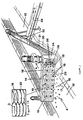
- the crude sewage containing solids 10 flows along a feed channel 12 in the direction of arrow A to the device 14, which is mounted to extend at an angle across the feed channel.
- the device 14 comprises upper and lower members 19, 20 and discs 18 rigidly mounted on shafts 16 which are mounted for rotation about parallel axes in bearings supported by members 19 and 20.
- the discs with the exception of the discs 18′ mounted on the extreme right-hand shaft 16′, bear serrations 22 on their peripheries.
- the shafts rotate and the discs all move in the same rotational sense, indicated by arrow B. Successive shafts move progressively faster with the right-hand shaft 16′ moving the fastest.
- the liquid part of the sewage is able to flow through the device 14 without significant resistance so that screened sewage therefore continues along the feed channel 12 in the direction of arrow A′.
- a barrier to the solid matter in the sewage is presented by the rotating discs however. Owing to increasing speed of rotation of successive shafts, a positive displacement of the solids towards the fastest moving shaft 16′ is promoted, whereupon the solids are either disintegrated in the flow or removed to a solids grinder 24 comprising two parallel shafts 26, mounted with discs 28, which rotate in opposite senses.
- the material is moved by an inclined upwardly helical conveyor 30 mounted above a screen 31.
- Water jets (not shown) spray water to wash the macerated screenings, which comprises both faecal matter and non-biodegradable material such as plastic and rubber.
- the macerated faecal matter is returned to the flow in the feed channel 12 through the screen 31 and is transported downstream for biological treatment, whereas the remaining material passes down a pipe 32 on to a conveyor belt 34 and is removed from the system in the direction of arrow C.
- Figure 1a shows the interleaved arrangement of the discs 18, which in this embodiment are provided with serrations 22. In operation the discs 18 rotate in the sense indicated by arrow B.
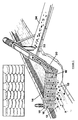
- FIG 2 the liquid material containing solid matter 10 flows in the feed channel 12 in the direction of arrow A.
- a device 14 as described in connection with Figure 1 is mounted with the shafts extending vertically at an angle across the feed channel. Whilst liquid material flows past the device, solid matter 10 is taken up on the discs 18, passes from left to right towards the fastest moving shaft 16′, proceeds, as in Figure 1, into an inclined helical conveyor 30 and continues down a pipe 32 on to a conveyor belt 34 which carries it out of the system.
- each disc may be provided with a radial rib to act as a moving wiper to clean the adjacent interleaved disc.
Landscapes
- Chemical Kinetics & Catalysis (AREA)
- Chemical & Material Sciences (AREA)
- Eye Examination Apparatus (AREA)
- Separation Of Solids By Using Liquids Or Pneumatic Power (AREA)
- Massaging Devices (AREA)
- Dry Shavers And Clippers (AREA)
- Preparation Of Compounds By Using Micro-Organisms (AREA)
- Photoreceptors In Electrophotography (AREA)
- Transplanting Machines (AREA)
- Treatment Of Sludge (AREA)
- Sampling And Sample Adjustment (AREA)
- Automatic Analysis And Handling Materials Therefor (AREA)
- Non-Silver Salt Photosensitive Materials And Non-Silver Salt Photography (AREA)
- Noodles (AREA)
Claims (9)
- Siebsystem, welches einen Strömungskanal (12) und eine Siebvorrichtung (14) aufweist, welche in dem Strömungskanal angeordnet ist und eine Anzahl von Sätzen von im wesentlichen ebenen Scheiben (18) aufweist, welche parallele, flache Stirnflächen aufweisen, wobei die Scheiben eines jeden Satzes auf eine Welle (16) im axialen Abstand zueinander montiert sind, wobei eine Einrichtung (19,20) vorgesehen ist, in welcher die Wellen längs einander paralleler Achsen montiert sind, wobei sich die auf einander benachbarte Wellen montierten Scheiben einander überlappen, und wobei eine Einrichtung vorgesehen ist, welche die Wellen unabhängig voneinander in die gleiche Drehrichtung dreht, die aufeinanderfolgend benachbarten Wellen zunehmend schneller rotieren, die Scheiben (18) von jedem Satz fest auf ihre zugehörige Welle montiert sind, und die Stirnflächen der Scheiben im wesentlichen senkrecht zu der Achse der zugehörigen Welle verlaufen, dadurch gekennzeichnet, daß die Achsen der Wellen vertikal montiert sind und daß die Stirnflächen den Stirnflächen von auf einer benachbarten Welle montierten Scheiben oder von Scheiben einer Mehrzahl von benachbarten Wellen in einem engen Abstand zugewandt sind, um dazwischen Schlitze mit parallelen Wänden auszubilden.
- Siebsystem nach Anspruch 1, dadurch gekennzeichnet, daß zumindest einige der Scheiben mit einem Kratzer oder Kratzern versehen sind, welche dazu ausgebildet sind, Material von den Scheiben zu entfernen.
- Siebsystem nach Anspruch 1 oder 2, dadurch gekennzeichnet, daß zumindest einige der Scheiben rings ihres Umfangs mit Zähnen (22) versehen sind.
- Siebsystem nach Anspruch 3, dadurch gekennzeichnet, daß die auf der letzten Welle angeordneten Scheiben keine Zähne aufweisen.
- Siebsystem nach einem der vorangehenden Ansprüche, dadurch gekennzeichnet, daß eine Ebene, in welcher die Achsen der Wellen sich erstrecken, in einem Winkel zu dem Strömungskanal quer über den Strömungskanal verläuft, wobei die am schnellsten rotierende Scheibe am weitesten stromabwärts angeordnet ist.
- Siebsystem nach einem der vorangehenden Ansprüche, dadurch gekennzeichnet, daß eine Zerkleinerungsanlage (24) derart angeordnet ist, daß sie die Feststoffpartikel von den Scheiben der letzten Welle aufnimmt.
- Siebsystem nach einem der vorangehenden Ansprüche, dadurch gekennzeichnet, daß stromabwärts der Siebvorrichtung eine Einrichtung zum biologischen Behandeln oder Abbau des flüssigen Materials vorgesehen ist, welches den Strömungskanal hinunterströmt.
- Verfahren zum Sieben, Zerkleinern oder Fördern eines flüssigen Materials mit darin enthaltenen Feststoffpartikeln, wobei das flüssige Material entlang des Kanals eines Systems nach einem der vorangehenden Ansprüche passiert und das flüssige Material mit den darin enthaltenen Feststoffpartikeln derart gesiebt wird, daß die Feststoffpartikel im wesentlichen horizontal zu einer Seite des Kanals in einer Richtung von der am langsamsten rotierenden Welle zu der am schnellsten rotierenden Welle gefördert werden, während die Feststoffpartikel in der Flüssigkeitsströmung verbleiben, welcher die Scheiben ausgesetzt sind.
- Verfahren nach Anspruch 8, dadurch gekennzeichnet, daß das flüssige Material Rohabwasser oder Klärschlamm ist.
Priority Applications (1)
| Application Number | Priority Date | Filing Date | Title |
|---|---|---|---|
| AT90305670T ATE84982T1 (de) | 1989-08-25 | 1990-05-24 | Siebvorrichtung. |
Applications Claiming Priority (2)
| Application Number | Priority Date | Filing Date | Title |
|---|---|---|---|
| GB8919332A GB2235392A (en) | 1989-08-25 | 1989-08-25 | Screening device |
| GB8919332 | 1989-08-25 |
Publications (2)
| Publication Number | Publication Date |
|---|---|
| EP0414341A1 EP0414341A1 (de) | 1991-02-27 |
| EP0414341B1 true EP0414341B1 (de) | 1993-01-27 |
Family
ID=10662103
Family Applications (1)
| Application Number | Title | Priority Date | Filing Date |
|---|---|---|---|
| EP90305670A Expired - Lifetime EP0414341B1 (de) | 1989-08-25 | 1990-05-24 | Siebvorrichtung |
Country Status (7)
| Country | Link |
|---|---|
| US (1) | US5061380A (de) |
| EP (1) | EP0414341B1 (de) |
| AT (1) | ATE84982T1 (de) |
| AU (1) | AU623999B2 (de) |
| DE (1) | DE69000822T2 (de) |
| ES (1) | ES2037523T3 (de) |
| GB (1) | GB2235392A (de) |
Families Citing this family (25)
| Publication number | Priority date | Publication date | Assignee | Title |
|---|---|---|---|---|
| US5505388A (en) | 1994-09-29 | 1996-04-09 | Disposable Waste Company, Inc. | Integrated diverter and waste comminutor |
| AU700616B2 (en) * | 1994-09-29 | 1999-01-07 | Jwc Environmental | Integrated diverter and waste macerator |
| NZ311927A (en) * | 1995-06-16 | 1999-01-28 | United States Filter Corp | Wastewater treatment with solids separation by filtering followed by maceration of solids |
| WO1997005338A1 (en) * | 1995-07-28 | 1997-02-13 | Swinburne University Of Technology | Separator |
| SE507499C2 (sv) * | 1996-10-07 | 1998-06-15 | Spirac Engineering Ab | Separationsanordning försedd med transportspiral och silorgan |
| FI102042B (fi) * | 1997-01-09 | 1998-10-15 | Toiminimi Etakotek | Suodatinlaite |
| US5840180A (en) * | 1997-06-02 | 1998-11-24 | John Meunier Inc. | Water flow segregating unit with endless screw |
| US5833152A (en) * | 1997-06-30 | 1998-11-10 | Galanty; William B. | Integrated comminuting screening and shredding system for liquid waste channels |
| US6176443B1 (en) * | 1998-09-25 | 2001-01-23 | Disposable Waste Systems, Inc. | Integrated diverter and waste comminutor |
| US6029290A (en) * | 1998-10-26 | 2000-02-29 | Skimmer Valet, Inc. | Swimming pool skimmer cleaner |
| CA2262076A1 (en) * | 1999-02-25 | 2000-08-25 | Rene Perreault | Separator for logs of wood |
| US6830207B2 (en) * | 2000-02-07 | 2004-12-14 | Franklin Miller, Inc. | Screen cleaning and comminuting system |
| US6311905B1 (en) | 2000-02-07 | 2001-11-06 | Franklin Miller, Inc. | Screen cleaning and comminuting system |
| US20040112810A1 (en) * | 2000-12-05 | 2004-06-17 | Christian Frommann | Device for separating and removing separation materials from a flowing liquid |
| JP4647150B2 (ja) * | 2001-08-07 | 2011-03-09 | 千住金属工業株式会社 | 酸化物の分離装置 |
| DE10316173B4 (de) * | 2003-04-04 | 2006-03-16 | Hans Huber Ag Maschinen- Und Anlagenbau | Vorrichtung zum Entfernen von feinem Siebgut aus einer Flüssigkeit |
| EP1778603A1 (de) * | 2004-06-14 | 2007-05-02 | Walter Schmid AG | Verfahren und vorrichtung zur entwässerung von gärrückstand |
| US7722762B2 (en) * | 2005-07-22 | 2010-05-25 | Laitram, L.L.C. | Horizontally traveling water screen |
| US7383842B1 (en) | 2006-08-03 | 2008-06-10 | Jwc Environmental | Screenings washer apparatus |
| US20080116151A1 (en) * | 2006-11-17 | 2008-05-22 | Clifford James Suthard | Methods of removing solids from liquids |
| US8727248B2 (en) | 2010-08-11 | 2014-05-20 | William Galanty | Comminutor with screening conditioner |
| US9567719B2 (en) * | 2013-04-03 | 2017-02-14 | Laitram, L.L.C. | Aquatic life and debris collection device for a water screen |
| JP6988282B2 (ja) * | 2017-09-04 | 2022-01-05 | 株式会社鶴見製作所 | 固液分離装置 |
| JP6401356B2 (ja) * | 2017-09-05 | 2018-10-10 | 株式会社鶴見製作所 | 固液分離装置 |
| CN113058319B (zh) * | 2021-04-13 | 2022-07-29 | 四川红土地农业开发有限公司 | 一种紫薯红酒加工用过滤装置及使用方法 |
Family Cites Families (8)
| Publication number | Priority date | Publication date | Assignee | Title |
|---|---|---|---|---|
| GB464158A (en) * | 1935-12-17 | 1937-04-13 | Watford Engineering Works Ltd | Improvements in or relating to paper-pulp and like straining machines |
| US3002625A (en) * | 1954-05-19 | 1961-10-03 | Fmc Corp | Screening and comminuting device |
| US2885079A (en) * | 1957-01-07 | 1959-05-05 | Infilco Inc | Apparatus for screening and comminuting |
| US3870627A (en) * | 1972-11-27 | 1975-03-11 | John W Herkes | Mechanical screening device for machine-harvested sugar cane |
| DE2811611C3 (de) * | 1978-03-17 | 1981-08-06 | Franz Grimme Landmaschinenfabrik, 2845 Damme | Enterdungsvorrichtung für Hackfrüchte |
| DE3617665A1 (de) * | 1986-05-26 | 1987-12-03 | Heinrich Beyke | Drehrechen |
| EP0268551B1 (de) * | 1986-10-06 | 1992-07-22 | Ueli Fritz Gut | Mechanischer Feststoffabscheider für Abwasser und Schlamm |
| US4919346A (en) * | 1987-11-27 | 1990-04-24 | Disposable Waste Systems, Inc. | Rotary screen diverter and solid waste handling system using same |
-
1989
- 1989-08-25 GB GB8919332A patent/GB2235392A/en not_active Withdrawn
-
1990
- 1990-05-24 AT AT90305670T patent/ATE84982T1/de active
- 1990-05-24 EP EP90305670A patent/EP0414341B1/de not_active Expired - Lifetime
- 1990-05-24 ES ES199090305670T patent/ES2037523T3/es not_active Expired - Lifetime
- 1990-05-24 DE DE9090305670T patent/DE69000822T2/de not_active Expired - Fee Related
- 1990-05-28 AU AU56014/90A patent/AU623999B2/en not_active Ceased
- 1990-05-31 US US07/530,360 patent/US5061380A/en not_active Expired - Fee Related
Also Published As
| Publication number | Publication date |
|---|---|
| EP0414341A1 (de) | 1991-02-27 |
| ATE84982T1 (de) | 1993-02-15 |
| GB8919332D0 (en) | 1989-10-11 |
| AU5601490A (en) | 1991-02-28 |
| DE69000822D1 (de) | 1993-03-11 |
| AU623999B2 (en) | 1992-05-28 |
| US5061380A (en) | 1991-10-29 |
| DE69000822T2 (de) | 1993-05-27 |
| ES2037523T3 (es) | 1993-06-16 |
| GB2235392A (en) | 1991-03-06 |
Similar Documents
| Publication | Publication Date | Title |
|---|---|---|
| US5061380A (en) | Screening system and method | |
| US4236999A (en) | Separation of solids from liquids by screening | |
| EP0375739B1 (de) | Wasserkläranlage für die beseitigung von teilchen, die grösser als ein vorbestimmter durchmesser sind | |
| US3876548A (en) | Screening method and apparatus | |
| US6378705B1 (en) | Apparatus for filtering plasticized thermoplastics | |
| KR970009367B1 (ko) | 수로에 흐르는 유체로부터 걸림물과/또는 여과물을 제거하기 위한 장치 | |
| US7344637B2 (en) | Apparatus for removing fine material from a liquid | |
| EP0946248B1 (de) | Filter mit gegenstromreinigung | |
| KR101574414B1 (ko) | 슬러리의 고형물 분리처리용 스크린설비의 회전 스크래이퍼 장치 | |
| EP0755293B1 (de) | Rotierender scheibenfilter | |
| US20240009599A1 (en) | Concentric Dual Drum Screen | |
| KR20010052565A (ko) | 펄프제조기 | |
| US5378375A (en) | Apparatus and method of washing screenings | |
| RU2156641C2 (ru) | Устройство для удаления осадка из протекающей по желобу жидкости | |
| US5833152A (en) | Integrated comminuting screening and shredding system for liquid waste channels | |
| US6773585B1 (en) | Device for separating fluids | |
| KR20180115042A (ko) | 준설토 투입 및 처리 시스템 | |
| US3392114A (en) | Apparatus and method for decontaminating pulp and paper machine effluent | |
| KR102601272B1 (ko) | 협잡물의 이송이 용이한 스크린 장치 및 스크린 장치의 이상동작 대응 방법 | |
| WO1984004293A1 (en) | A device for purification of liquid media such as waste water | |
| JP2019093386A (ja) | 破砕装置 | |
| USRE22199E (en) | Screen | |
| JPH0243406A (ja) | スクリーン式夾雑物処理装置 | |
| JP3634481B2 (ja) | 汚砂処理装置 | |
| JPS61149215A (ja) | 濾過装置 |
Legal Events
| Date | Code | Title | Description |
|---|---|---|---|
| PUAI | Public reference made under article 153(3) epc to a published international application that has entered the european phase |
Free format text: ORIGINAL CODE: 0009012 |
|
| AK | Designated contracting states |
Kind code of ref document: A1 Designated state(s): AT BE CH DE DK ES FR GB GR IT LI LU NL SE |
|
| 17P | Request for examination filed |
Effective date: 19910325 |
|
| 17Q | First examination report despatched |
Effective date: 19910806 |
|
| GRAA | (expected) grant |
Free format text: ORIGINAL CODE: 0009210 |
|
| ITF | It: translation for a ep patent filed | ||
| AK | Designated contracting states |
Kind code of ref document: B1 Designated state(s): AT BE CH DE DK ES FR GB GR IT LI LU NL SE |
|
| PG25 | Lapsed in a contracting state [announced via postgrant information from national office to epo] |
Ref country code: SE Effective date: 19930127 Ref country code: NL Effective date: 19930127 Ref country code: LI Effective date: 19930127 Ref country code: GR Free format text: LAPSE BECAUSE OF FAILURE TO SUBMIT A TRANSLATION OF THE DESCRIPTION OR TO PAY THE FEE WITHIN THE PRESCRIBED TIME-LIMIT Effective date: 19930127 Ref country code: DK Effective date: 19930127 Ref country code: CH Effective date: 19930127 Ref country code: BE Effective date: 19930127 Ref country code: AT Effective date: 19930127 |
|
| REF | Corresponds to: |
Ref document number: 84982 Country of ref document: AT Date of ref document: 19930215 Kind code of ref document: T |
|
| ET | Fr: translation filed | ||
| REF | Corresponds to: |
Ref document number: 69000822 Country of ref document: DE Date of ref document: 19930311 |
|
| REG | Reference to a national code |
Ref country code: CH Ref legal event code: PL |
|
| PG25 | Lapsed in a contracting state [announced via postgrant information from national office to epo] |
Ref country code: LU Free format text: LAPSE BECAUSE OF NON-PAYMENT OF DUE FEES Effective date: 19930531 |
|
| REG | Reference to a national code |
Ref country code: ES Ref legal event code: FG2A Ref document number: 2037523 Country of ref document: ES Kind code of ref document: T3 |
|
| NLV1 | Nl: lapsed or annulled due to failure to fulfill the requirements of art. 29p and 29m of the patents act | ||
| PLBE | No opposition filed within time limit |
Free format text: ORIGINAL CODE: 0009261 |
|
| STAA | Information on the status of an ep patent application or granted ep patent |
Free format text: STATUS: NO OPPOSITION FILED WITHIN TIME LIMIT |
|
| 26N | No opposition filed | ||
| REG | Reference to a national code |
Ref country code: FR Ref legal event code: ST |
|
| REG | Reference to a national code |
Ref country code: FR Ref legal event code: RN |
|
| REG | Reference to a national code |
Ref country code: FR Ref legal event code: D3 |
|
| PGFP | Annual fee paid to national office [announced via postgrant information from national office to epo] |
Ref country code: FR Payment date: 19970513 Year of fee payment: 8 |
|
| PGFP | Annual fee paid to national office [announced via postgrant information from national office to epo] |
Ref country code: GB Payment date: 19970515 Year of fee payment: 8 |
|
| PGFP | Annual fee paid to national office [announced via postgrant information from national office to epo] |
Ref country code: ES Payment date: 19970530 Year of fee payment: 8 Ref country code: DE Payment date: 19970530 Year of fee payment: 8 |
|
| PG25 | Lapsed in a contracting state [announced via postgrant information from national office to epo] |
Ref country code: GB Free format text: LAPSE BECAUSE OF NON-PAYMENT OF DUE FEES Effective date: 19980524 |
|
| PG25 | Lapsed in a contracting state [announced via postgrant information from national office to epo] |
Ref country code: ES Free format text: LAPSE BECAUSE OF EXPIRATION OF PROTECTION Effective date: 19980525 |
|
| PG25 | Lapsed in a contracting state [announced via postgrant information from national office to epo] |
Ref country code: FR Free format text: LAPSE BECAUSE OF NON-PAYMENT OF DUE FEES Effective date: 19980531 |
|
| GBPC | Gb: european patent ceased through non-payment of renewal fee |
Effective date: 19980524 |
|
| PG25 | Lapsed in a contracting state [announced via postgrant information from national office to epo] |
Ref country code: DE Free format text: LAPSE BECAUSE OF NON-PAYMENT OF DUE FEES Effective date: 19990302 |
|
| REG | Reference to a national code |
Ref country code: FR Ref legal event code: ST |
|
| REG | Reference to a national code |
Ref country code: ES Ref legal event code: FD2A Effective date: 20000201 |
|
| PG25 | Lapsed in a contracting state [announced via postgrant information from national office to epo] |
Ref country code: IT Free format text: LAPSE BECAUSE OF NON-PAYMENT OF DUE FEES;WARNING: LAPSES OF ITALIAN PATENTS WITH EFFECTIVE DATE BEFORE 2007 MAY HAVE OCCURRED AT ANY TIME BEFORE 2007. THE CORRECT EFFECTIVE DATE MAY BE DIFFERENT FROM THE ONE RECORDED. Effective date: 20050524 |