EP0414444A2 - Accumulateur de phase avec incrémentation tremblante d'accumulation à cause de composants de phase fins - Google Patents
Accumulateur de phase avec incrémentation tremblante d'accumulation à cause de composants de phase fins Download PDFInfo
- Publication number
- EP0414444A2 EP0414444A2 EP90308975A EP90308975A EP0414444A2 EP 0414444 A2 EP0414444 A2 EP 0414444A2 EP 90308975 A EP90308975 A EP 90308975A EP 90308975 A EP90308975 A EP 90308975A EP 0414444 A2 EP0414444 A2 EP 0414444A2
- Authority
- EP
- European Patent Office
- Prior art keywords
- fine
- phase
- register
- component
- accumulator
- Prior art date
- Legal status (The legal status is an assumption and is not a legal conclusion. Google has not performed a legal analysis and makes no representation as to the accuracy of the status listed.)
- Granted
Links
Images

Classifications
-
- G—PHYSICS
- G06—COMPUTING OR CALCULATING; COUNTING
- G06F—ELECTRIC DIGITAL DATA PROCESSING
- G06F1/00—Details not covered by groups G06F3/00 - G06F13/00 and G06F21/00
- G06F1/02—Digital function generators
- G06F1/03—Digital function generators working, at least partly, by table look-up
- G06F1/0321—Waveform generators, i.e. devices for generating periodical functions of time, e.g. direct digital synthesizers
- G06F1/0328—Waveform generators, i.e. devices for generating periodical functions of time, e.g. direct digital synthesizers in which the phase increment is adjustable, e.g. by using an adder-accumulator
-
- G—PHYSICS
- G06—COMPUTING OR CALCULATING; COUNTING
- G06F—ELECTRIC DIGITAL DATA PROCESSING
- G06F2211/00—Indexing scheme relating to details of data-processing equipment not covered by groups G06F3/00 - G06F13/00
- G06F2211/902—Spectral purity improvement for digital function generators by adding a dither signal, e.g. noise
Definitions
- the present invention generally pertains to phase accumulators, such as are used in direct digital frequency synthesizers, and is particularly directed to dithering the phase at which a coarse-component accumulator is incremented in response to accumulation of the fine phase components.
- a direct digital frequency synthesizer generates an analog waveform of a predetermined frequency from accumulated digital frequency words, which, as accumulated, represent the phase of a cyclic waveform, such as a sine wave of said predetermined frequency.
- a typical prior art direct digital frequency synthesizer includes a phase accumulator for accumulating the digital frequency words and a phase-to-magnitude converter for converting the accumulated phase value into an analog waveform of the predetermined frequency.
- the phase-to-magnitude converter converts the phase value accumulated in the phase accumulator into an analog signal magnitude for the phase angle of the cyclic waveform that is represented by the phase value in the phase accumulator.
- the phase accumulator has a length of m bits and is driven at a clock rate f c . At each clock pulse, a frequency word having a length of k bits is added to the present value in the phase accumulator. The value in the phase accumulator increases at this rate until it overflows losing all bits that exceed 2 m -1.
- the phase value in the phase accumulator at any time represents the instantaneous phase angle of the cyclic waveform over a range of 2 ⁇ radians.
- the actual output frequency is g times f c /2 m , where g can range from one to 2 m .
- the frequency resolution is also equal to f c /2 m , which means that the resolution requirements can generally be met by trading off f c and m.
- the phase accumulator performs a phase calculation once each clock cycle by adding the frequency word, which is proportional to the desired output frequency, to the contents of the phase accumulator.
- phase accumulator is divided into a coarse-component accumulator and a fine-component accumulator.
- the full m bits are partitioned into c bits in the coarse-component accumulator and f bits in the fine-component accumulator. Only the c bits of the coarse-component accumulator are used to determine the phase value for one cycle of phase accumulator output, whereby phase resolution is limited to 2 ⁇ /2 c radians.
- Both the coarse-component accumulator and the fine-component accumulator are clocked to run at a frequency of f c .
- the minimum frequency that the coarse-component accumulator can provide is f c /2 c Hz.
- the output phase function generally has a phase error with respect to the total phase function contained in the phase accumulator.
- the phase error is slightly periodic in time, with the resultant effect of spurious lines or phase modulation (PM) spurs (spurious signals) in the output spectrum.
- phase errors due to PM spurs can be suppressed by dithering the phase at which the coarse-component accumulator is incremented in response to accumulation of the fine phase components.
- the present invention provides a phase accumulator in which the phase of incrementing the coarse-component register is randomly dithered in such manner that the dithering process itself does not introduce further PM spurs.
- the present invention is a phase accumulator for accumulating digital frequency words, which, as accumulated, represent the phase of a cyclic waveform of a predetermined frequency, with the phase accumulator including a coarse-component accumulator for accumulating coarse phase components of the digital frequency words; a fine-component accumulator for accumulating fine phase components of the digital frequency words; and means for incrementing the coarse-component accumulator in response to accumulation of the fine phase components, wherein said incrementing means comprise means for providing a variable randomly generated value for each fine-component accumulation cycle; means for periodically sampling the accumulation of the fine phase components in relation to the randomly generated value; and means for incrementing the coarse component register for each fine-component accumulation cycle, with the phase of said incrementing being dithered in accordance with the number of times the accumulated fine phase components exceed the randomly generated values during the sampling period.
- a sampling period is the interval between the sampling times S, as determined by the phase accumulator clock signal.
- the relative durations of the fine-component-accumulation cycles and the sampling periods depends upon the sampling rate and the ratio of the values of the fine phase components of the digital frequency words to the value of the least significant bit of the coarse-component accumulator.
- the duration of the average fine-component-accumulation cycle is approximately twice that of the sampling period.
- the only anomalous components introduced by the randomly dithered phase incrementing scheme of the present invention are harmonics of the sampling frequency, which are already present in the phase accumulator by virtue of the phase accumulator being clocked at the sampling rate.
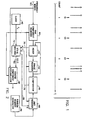
- one preferred embodiment of the phase accumulator of the present invention includes an f-bit fine-component register 60, an adder 62, a phase register 64, a comparator 66, a limit register 68, a random number generator 70, a state machine 72, a c-bit coarse-component accumulator 48 and a clock 45.
- the f-bit fine-component register 60, the phase register 64, the limit register 68, the state machine 72, and the c-bit coarse-component accumulator 48 are synchronously clocked at a rate f c by a clock signal provided by the clock 45.
- the phase accumulator is an m-bit accumulator for accumulating phase components of k-bit digital frequency words 52.
- the digital frequency words 52 as accumulated, represent the phase of a sine wave of a predetermined frequency.
- the c-bit coarse-component accumulator 48 accumulates coarse phase components of the digital frequency words 52; and the f-bit fine-component register 60 registers fine phase components of the digital frequency words 52.
- the fine phase components are shifted in parallel from the fine- component register 60 through the adder 62 into the phase register 64, and are accumulated in the phase register 64. Whenever the fine phase components accumulated in the phase register 64 exceed the capacity of the phase register 64, the adder 62 responds by providing an accumulator carry bit "A" to the state machine 72 via line 76.
- the coarse-component accumulator 48 includes a coarse-component register, an adder and a phase register configured and operable in the same manner as the fine-component register 60, the adder 62 and the phase register 64.
- the comparator 66 compares the value in the phase register 64 with the value in the limit register 68, and provides a comparator carry bit "C" to the state machine 72 via line 78 whenever the value in the phase register 64 exceeds the value in the limit register 68.
- the value in the limit register 68 is provided by the random number generator 70. A new value is entered into the limit register 68 from the random number generator 70 each time an enable signal "E" is provided on line 80 by the state machine 72.
- the random number generator 70 is either a truly random number generator, as implemented by a noise quantization processor, for example, or a pseudo random number generator, as implemented by a shift register sequence generator, for example.
- the term "random number”, as used herein, means both truly random numbers and pseudo random numbers.
- the state machine 72 Each time the state machine 72 is sampled by the clock signal from the clock 45, the state machine 72 provides a carry count of either 0, 1, or 2 to the coarse-component register 48 via lines 82 in accordance with the number of times the accumulated fine phase components exceed the randomly generated value during the sampling period, as indicated by a combination of the state of the state machine 72 and whether an accumulator carry bit A and/or a comparator carry bit C is provided to the state machine 72 when the state machine 72 is sampled.
- the adder of the coarse-component accumulator 48 increments the accumulated coarse phase components in the phase register thereof by the carry count on line 82 from the state machine 72 together with and at the same time as when it increments such accumulated coarse phase components by the coarse phase component in the coarse-component register thereof.
- a state diagram for the state machine 72 is set forth as Figure 3; and Table 1 sets forth the response of the state machine 72 to the combinations of the accumulator carry bit A and the comparator carry bit C during each of three different states of the state machine 91.
- Table 1 STATE A C COUNT E NEXT STATE 1 0 0 0 0 1 1 0 1 0 0 0 1 1 1 0 0 0 2 1 1 1 0 0 2 2 0 0 0 0 0 2 2 0 1 1 1 1 2 1 0 0 1 3 2 1 1 1 1 1 2 3 0 0 1 0 2 3 0 1 2 1 1 3 1 0 1 1 3 3 3 1 1 2 1 2
- the first state 1, state 1, represents the previous sampling period; the second state, state 2, represents the present sampling period; and the third state, state 3, represent the next sampling period.
- the "E” column indicates the conditions under which an enable signal E is provided by the state machine 72 to the limit register 68 for registering a new random value in the limit register 68.
- the "NEXT STATE” column indicates the state of the state machine 72 during the subsequent sampling period.
- phase accumulator of the present invention includes an f-bit fine-component register 84, an adder 85, a phase register 86, a first comparator 87, a second comparator 88, a limit register 89, a random number generator 90, a state machine 91, a c-bit coarse-component accumulator 48 and a clock 45.
- the f-bit fine-component register 84, the phase register 86, the limit register 89, the state machine 91, and the c-bit coarse-component accumulator 48 are synchronously clocked at a rate f c by a clock signal provided by the clock 45.
- the phase accumulator is an m-bit accumulator for accumulating phase components of k-bit digital frequency words 52.
- the digital frequency words 52 as accumulated, represent the phase of a sine wave of a predetermined frequency.
- the c-bit coarse-component accumulator 48 accumulates coarse phase components of the digital frequency words 52; and the f-bit fine-component register 84 registers fine phase components of the digital frequency words 52.
- the fine phase components are shifted in parallel from the fine-component register 84 through the adder 85 into the phase register 86, and are accumulated in the phase register 86. Whenever the fine phase components accumulated in the phase register 86 exceed the capacity of the phase register 86, the adder 85 responds by providing an accumulator carry bit "A" to the state machine 91 via line 93.
- the coarse component-accumulator 48 includes a coarse-component register, an adder and a phase register configured and operable in the same manner as the fine-component register 84, the adder 85 and the phase register 86.
- the first comparator 87 compares the value in the phase register 86 with the value then provided by the random number generator 90 and provides a comparator carry bit "C1" to the state machine 91 via line 94 whenever the value in the phase register 86 exceeds the value then provided by the random number generator 90.
- the second comparator 88 compares the value in the phase register 86 with the value in the limit register 89, and provides a comparator carry bit "C2" to the state machine 91 via line 95 whenever the value in the phase register 86 exceeds the value in the limit register 89.
- the value in the limit register 89 is provided by the random number generator 90. A new value is entered into the limit register 89 from the random number generator 90 in response to each clock pulse from the clock 45. The value in the limit register 89 is the same as that provided by the random number generator 90 during the previous sampling period.
- the use of the two comparators 87, 88 in comparison to the use of only one comparator in the embodiment of Figure 2 allows the limit register 89 to be loaded independently of the functioning of the state machine 91, which in turn enables the generation of the accumulator carry bit A to be fully pipelined with the generation of the comparator carry bits C1 and C2.
- the value of the fine phase components of the frequency words 52 must be at least one-half the value of the least significant bit of the coarse-component accumulator 48, which in turn limits the number of comparisons to not more than two during any one fine-phase-component-accumulation period.
- the state machine 91 Each time the state machine 91 is sampled by the clock signal from the clock 45, the state machine 91 provides a carry count of either 0, 1, or 2 to the coarse-component register 48 via lines 97 in accordance with the number of times the accumulated fine phase components exceed the randomly generated value during the sampling period, as indicated by a combination of the state of the state machine 91 and whether an accumulator carry bit A and/or a comparator carry bit C1 or C2 is provided to the state machine 91 when the state machine 91 is sampled.
- the adder of the coarse-component accumulator 48 increments the accumulated coarse phase components in the phase register thereof by the carry count on line 97 from the state machine 91 together with and at the same time as when it increments such accumulated coarse phase components by the coarse phase component in the coarse-component register thereof.
- Table 2 sets forth the response of the state machine 91 to the combinations of the accumulator carry bit A and the comparator carry bits C1 and C2 during each of four different states of the state machine 91.
- Table 2 STATE A C1 C2 COUNT NEXT STATE 1 0 0 ⁇ 1 3 1 0 1 ⁇ 2 4 1 1 0 ⁇ 1 1 1 1 1 ⁇ 2 2 2 0 0 ⁇ 0 3 2 0 1 ⁇ 1 4 2 1 0 ⁇ 0 1 2 1 1 ⁇ 1 2 3 0 ⁇ 0 * * 3 0 ⁇ 1 * * 3 1 ⁇ 0 0 1 3 1 ⁇ 1 1 2 4 0 ⁇ ⁇ * * 4 1 ⁇ ⁇ 0 2
- the first state, state 1, of the state machine 91 is a state in which the comparison is made by the first comparatiro 87 in a sampling period following a sampling period in which no comparator carry bit C1 or C2 was provided;
- the second state, state 2 is a state in which the comparison is made by the first comparator 87 in a sampling period following a sampling period in which a comparator carry bit C1 or C2 was provided;
- the third state, state 3, is a state in which the comparison is made by the second comparator 88;
- the fourth state, state 4 is a sampling period following a first or second state sampling period in which a comparator carry bit C1 or C2 was provided but an accumulator carry bit A was not provided.
- the "NEXT STATE" column indicates the state of the state machine 91 during the subsequent sampling period.
Landscapes
- Engineering & Computer Science (AREA)
- Theoretical Computer Science (AREA)
- Physics & Mathematics (AREA)
- General Engineering & Computer Science (AREA)
- General Physics & Mathematics (AREA)
- Stabilization Of Oscillater, Synchronisation, Frequency Synthesizers (AREA)
- Medicines That Contain Protein Lipid Enzymes And Other Medicines (AREA)
- Manipulation Of Pulses (AREA)
- Analogue/Digital Conversion (AREA)
Applications Claiming Priority (2)
| Application Number | Priority Date | Filing Date | Title |
|---|---|---|---|
| US07/398,703 US4984186A (en) | 1989-08-25 | 1989-08-25 | Phase accumulator with dithered incrementing of accumulation due to fine phase components |
| US398703 | 1989-08-25 |
Publications (3)
| Publication Number | Publication Date |
|---|---|
| EP0414444A2 true EP0414444A2 (fr) | 1991-02-27 |
| EP0414444A3 EP0414444A3 (en) | 1992-04-08 |
| EP0414444B1 EP0414444B1 (fr) | 1995-02-15 |
Family
ID=23576455
Family Applications (1)
| Application Number | Title | Priority Date | Filing Date |
|---|---|---|---|
| EP90308975A Expired - Lifetime EP0414444B1 (fr) | 1989-08-25 | 1990-08-15 | Accumulateur de phase avec incrémentation tremblante d'accumulation à cause de composants de phase fins |
Country Status (6)
| Country | Link |
|---|---|
| US (1) | US4984186A (fr) |
| EP (1) | EP0414444B1 (fr) |
| JP (1) | JPH03143106A (fr) |
| AU (1) | AU625793B2 (fr) |
| CA (1) | CA2023327A1 (fr) |
| DE (1) | DE69016883T2 (fr) |
Cited By (4)
| Publication number | Priority date | Publication date | Assignee | Title |
|---|---|---|---|---|
| US5231828A (en) * | 1992-02-26 | 1993-08-03 | M & W Gear Company | Wrapping mechanism for round balers |
| EP1255355A1 (fr) * | 2001-04-26 | 2002-11-06 | Texas Instruments Incorporated | Système et procédé de production d'un signal de gigue sur une entrée d'accord d'un oscillateur contrôlé numériquement |
| US6606004B2 (en) | 2000-04-20 | 2003-08-12 | Texas Instruments Incorporated | System and method for time dithering a digitally-controlled oscillator tuning input |
| EP1351397A3 (fr) * | 2001-11-27 | 2005-03-02 | Texas Instruments Incorporated | Synthèse entièrement numérique de fréquence avec réintroduction capacitive d'informations d'accord à tremblement |
Families Citing this family (10)
| Publication number | Priority date | Publication date | Assignee | Title |
|---|---|---|---|---|
| US5495505A (en) * | 1990-12-20 | 1996-02-27 | Motorola, Inc. | Increased frequency resolution in a synthesizer |
| US5371765A (en) * | 1992-07-10 | 1994-12-06 | Hewlett-Packard Company | Binary phase accumulator for decimal frequency synthesis |
| US5329260A (en) * | 1992-07-17 | 1994-07-12 | Ii Morrow Inc. | Numerically-controlled modulated oscillator and modulation method |
| US5416434A (en) * | 1993-03-05 | 1995-05-16 | Hewlett-Packard Corporation | Adaptive clock generation with pseudo random variation |
| US5365182A (en) * | 1993-06-22 | 1994-11-15 | Motorola, Inc. | Method and apparatus for low power clock generation for high speed applications |
| US5736592A (en) * | 1995-02-15 | 1998-04-07 | Enichem S.P.A. | Process for intramolecularly condensing a non-linear optical polyamic acid composition |
| US6636092B1 (en) * | 2000-09-14 | 2003-10-21 | 3Com Corporation | Digital receive phase lock loop with cumulative phase error correction |
| US7522099B2 (en) * | 2005-09-08 | 2009-04-21 | Topcon Gps, Llc | Position determination using carrier phase measurements of satellite signals |
| US8063669B2 (en) * | 2008-11-06 | 2011-11-22 | Nokia Corporation | Frequency synthesizer having a plurality of independent output tones |
| US7948274B2 (en) * | 2009-09-30 | 2011-05-24 | Nokia Corporation | Frequency generation circuitry and method |
Family Cites Families (7)
| Publication number | Priority date | Publication date | Assignee | Title |
|---|---|---|---|---|
| US3946215A (en) * | 1974-09-30 | 1976-03-23 | The Boeing Company | Pseudo-random code generator |
| US4327419A (en) * | 1980-02-22 | 1982-04-27 | Kawai Musical Instrument Mfg. Co., Ltd. | Digital noise generator for electronic musical instruments |
| US4652832A (en) * | 1985-07-05 | 1987-03-24 | Motorola, Inc. | Frequency resolution in a digital oscillator |
| US4901265A (en) * | 1987-12-14 | 1990-02-13 | Qualcomm, Inc. | Pseudorandom dither for frequency synthesis noise |
| US4905177A (en) * | 1988-01-19 | 1990-02-27 | Qualcomm, Inc. | High resolution phase to sine amplitude conversion |
| US4935891A (en) * | 1988-12-22 | 1990-06-19 | Xerox Corporation | Pseudo-random phase shifted arithmetic bit clock generators for digital printers |
| US4935871A (en) * | 1989-02-23 | 1990-06-19 | Caterpillar Inc. | Electronic road system generation method for an automatic guided vehicle |
-
1989
- 1989-08-25 US US07/398,703 patent/US4984186A/en not_active Expired - Fee Related
-
1990
- 1990-08-15 DE DE69016883T patent/DE69016883T2/de not_active Expired - Fee Related
- 1990-08-15 CA CA002023327A patent/CA2023327A1/fr not_active Abandoned
- 1990-08-15 EP EP90308975A patent/EP0414444B1/fr not_active Expired - Lifetime
- 1990-08-20 AU AU61119/90A patent/AU625793B2/en not_active Ceased
- 1990-08-24 JP JP2224136A patent/JPH03143106A/ja active Pending
Cited By (4)
| Publication number | Priority date | Publication date | Assignee | Title |
|---|---|---|---|---|
| US5231828A (en) * | 1992-02-26 | 1993-08-03 | M & W Gear Company | Wrapping mechanism for round balers |
| US6606004B2 (en) | 2000-04-20 | 2003-08-12 | Texas Instruments Incorporated | System and method for time dithering a digitally-controlled oscillator tuning input |
| EP1255355A1 (fr) * | 2001-04-26 | 2002-11-06 | Texas Instruments Incorporated | Système et procédé de production d'un signal de gigue sur une entrée d'accord d'un oscillateur contrôlé numériquement |
| EP1351397A3 (fr) * | 2001-11-27 | 2005-03-02 | Texas Instruments Incorporated | Synthèse entièrement numérique de fréquence avec réintroduction capacitive d'informations d'accord à tremblement |
Also Published As
| Publication number | Publication date |
|---|---|
| EP0414444A3 (en) | 1992-04-08 |
| JPH03143106A (ja) | 1991-06-18 |
| AU6111990A (en) | 1991-02-28 |
| DE69016883T2 (de) | 1995-06-08 |
| CA2023327A1 (fr) | 1991-02-26 |
| US4984186A (en) | 1991-01-08 |
| DE69016883D1 (de) | 1995-03-23 |
| EP0414444B1 (fr) | 1995-02-15 |
| AU625793B2 (en) | 1992-07-16 |
Similar Documents
| Publication | Publication Date | Title |
|---|---|---|
| EP0414444A2 (fr) | Accumulateur de phase avec incrémentation tremblante d'accumulation à cause de composants de phase fins | |
| EP0414445B1 (fr) | Synthétiseur de fréquence numérique direct | |
| US3735269A (en) | Digital frequency synthesizer | |
| US4764748A (en) | Analog-to-digital conversion apparatus with dither signal | |
| US5774084A (en) | Method and apparatus for translating digital data into an analog signal | |
| Reinhardt | Spur reduction techniques in direct digital synthesizers | |
| US5821816A (en) | Integer division variable frequency synthesis apparatus and method | |
| Vankka | Spur reduction techniques in sine output direct digital synthesis | |
| CA1175148A (fr) | Generateur de tremblottements numeriques de decalage | |
| WO2002071614A1 (fr) | Diviseur de frequence sigma delta par n fractions aux performances bruit et spur ameliorees | |
| JPH03253108A (ja) | ダイレクト・デジタル・シンセサイザー及び信号発生方法 | |
| US4963839A (en) | Wide bandwidth phase locked loop circuit with sliding window averager | |
| US4145667A (en) | Phase locked loop frequency synthesizer using digital modulo arithmetic | |
| EP0782062B1 (fr) | Réduction de bruit dans des synthétiseurs de fréquence numériques | |
| JPH01131918A (ja) | Ad変換器 | |
| EP0452031A2 (fr) | Génération de signaux utilisant une conversion numérique-analogique | |
| US7385537B2 (en) | Linear feedback shift register first-order noise generator | |
| US20100259425A1 (en) | Digital signal processing device | |
| US6735265B1 (en) | Comparator | |
| US6518802B1 (en) | Circuits and methods for generating an accurate digital representation of a sinusoidal wave | |
| US20100134151A1 (en) | Method for locking a synthesised output signal of a synthesised waveform synthesiser in a phase relationship | |
| US6593815B2 (en) | Full digital phase locked loop and circuitry for utilizing the same | |
| US6476747B1 (en) | Digital to analog converter | |
| EP0322743A2 (fr) | Générateur de signaux | |
| SU1254576A1 (ru) | Синтезатор частот |
Legal Events
| Date | Code | Title | Description |
|---|---|---|---|
| PUAI | Public reference made under article 153(3) epc to a published international application that has entered the european phase |
Free format text: ORIGINAL CODE: 0009012 |
|
| 17P | Request for examination filed |
Effective date: 19901221 |
|
| AK | Designated contracting states |
Kind code of ref document: A2 Designated state(s): DE FR GB IT |
|
| PUAL | Search report despatched |
Free format text: ORIGINAL CODE: 0009013 |
|
| AK | Designated contracting states |
Kind code of ref document: A3 Designated state(s): DE FR GB IT |
|
| 17Q | First examination report despatched |
Effective date: 19931103 |
|
| RAP1 | Party data changed (applicant data changed or rights of an application transferred) |
Owner name: THE TITAN CORPORATION |
|
| GRAA | (expected) grant |
Free format text: ORIGINAL CODE: 0009210 |
|
| AK | Designated contracting states |
Kind code of ref document: B1 Designated state(s): DE FR GB IT |
|
| ET | Fr: translation filed | ||
| REF | Corresponds to: |
Ref document number: 69016883 Country of ref document: DE Date of ref document: 19950323 |
|
| ITF | It: translation for a ep patent filed | ||
| PLBE | No opposition filed within time limit |
Free format text: ORIGINAL CODE: 0009261 |
|
| STAA | Information on the status of an ep patent application or granted ep patent |
Free format text: STATUS: NO OPPOSITION FILED WITHIN TIME LIMIT |
|
| 26N | No opposition filed | ||
| PGFP | Annual fee paid to national office [announced via postgrant information from national office to epo] |
Ref country code: GB Payment date: 19970808 Year of fee payment: 8 |
|
| PGFP | Annual fee paid to national office [announced via postgrant information from national office to epo] |
Ref country code: FR Payment date: 19970828 Year of fee payment: 8 |
|
| PGFP | Annual fee paid to national office [announced via postgrant information from national office to epo] |
Ref country code: DE Payment date: 19970915 Year of fee payment: 8 |
|
| PG25 | Lapsed in a contracting state [announced via postgrant information from national office to epo] |
Ref country code: GB Free format text: LAPSE BECAUSE OF NON-PAYMENT OF DUE FEES Effective date: 19980815 |
|
| GBPC | Gb: european patent ceased through non-payment of renewal fee |
Effective date: 19980815 |
|
| PG25 | Lapsed in a contracting state [announced via postgrant information from national office to epo] |
Ref country code: FR Free format text: LAPSE BECAUSE OF NON-PAYMENT OF DUE FEES Effective date: 19990430 |
|
| PG25 | Lapsed in a contracting state [announced via postgrant information from national office to epo] |
Ref country code: DE Free format text: LAPSE BECAUSE OF NON-PAYMENT OF DUE FEES Effective date: 19990601 |
|
| REG | Reference to a national code |
Ref country code: FR Ref legal event code: ST |
|
| PG25 | Lapsed in a contracting state [announced via postgrant information from national office to epo] |
Ref country code: IT Free format text: LAPSE BECAUSE OF NON-PAYMENT OF DUE FEES;WARNING: LAPSES OF ITALIAN PATENTS WITH EFFECTIVE DATE BEFORE 2007 MAY HAVE OCCURRED AT ANY TIME BEFORE 2007. THE CORRECT EFFECTIVE DATE MAY BE DIFFERENT FROM THE ONE RECORDED. Effective date: 20050815 |