EP0414554A2 - Procédé et dispositif de fabrication de pneus - Google Patents
Procédé et dispositif de fabrication de pneus Download PDFInfo
- Publication number
- EP0414554A2 EP0414554A2 EP90309286A EP90309286A EP0414554A2 EP 0414554 A2 EP0414554 A2 EP 0414554A2 EP 90309286 A EP90309286 A EP 90309286A EP 90309286 A EP90309286 A EP 90309286A EP 0414554 A2 EP0414554 A2 EP 0414554A2
- Authority
- EP
- European Patent Office
- Prior art keywords
- band
- forming drum
- tread
- band forming
- supply means
- Prior art date
- Legal status (The legal status is an assumption and is not a legal conclusion. Google has not performed a legal analysis and makes no representation as to the accuracy of the status listed.)
- Withdrawn
Links
Images


Classifications
-
- B—PERFORMING OPERATIONS; TRANSPORTING
- B29—WORKING OF PLASTICS; WORKING OF SUBSTANCES IN A PLASTIC STATE IN GENERAL
- B29D—PRODUCING PARTICULAR ARTICLES FROM PLASTICS OR FROM SUBSTANCES IN A PLASTIC STATE
- B29D30/00—Producing pneumatic or solid tyres or parts thereof
- B29D30/06—Pneumatic tyres or parts thereof (e.g. produced by casting, moulding, compression moulding, injection moulding, centrifugal casting)
- B29D30/08—Building tyres
- B29D30/20—Building tyres by the flat-tyre method, i.e. building on cylindrical drums
- B29D2030/202—Building tyres by the flat-tyre method, i.e. building on cylindrical drums the building drums being movable, i.e. not permanently connected to a fixed frame
-
- B—PERFORMING OPERATIONS; TRANSPORTING
- B29—WORKING OF PLASTICS; WORKING OF SUBSTANCES IN A PLASTIC STATE IN GENERAL
- B29D—PRODUCING PARTICULAR ARTICLES FROM PLASTICS OR FROM SUBSTANCES IN A PLASTIC STATE
- B29D30/00—Producing pneumatic or solid tyres or parts thereof
- B29D30/06—Pneumatic tyres or parts thereof (e.g. produced by casting, moulding, compression moulding, injection moulding, centrifugal casting)
- B29D30/08—Building tyres
- B29D30/20—Building tyres by the flat-tyre method, i.e. building on cylindrical drums
- B29D2030/204—Building tyres by the flat-tyre method, i.e. building on cylindrical drums the fixtures supporting the cylindrical drums, e.g. turrets, being displaceable, e.g. movable along a path, rail or the like
-
- B—PERFORMING OPERATIONS; TRANSPORTING
- B29—WORKING OF PLASTICS; WORKING OF SUBSTANCES IN A PLASTIC STATE IN GENERAL
- B29D—PRODUCING PARTICULAR ARTICLES FROM PLASTICS OR FROM SUBSTANCES IN A PLASTIC STATE
- B29D30/00—Producing pneumatic or solid tyres or parts thereof
- B29D30/06—Pneumatic tyres or parts thereof (e.g. produced by casting, moulding, compression moulding, injection moulding, centrifugal casting)
- B29D30/08—Building tyres
- B29D30/20—Building tyres by the flat-tyre method, i.e. building on cylindrical drums
- B29D2030/205—A single building drum being mounted on a fixture or supporting device, e.g. turret or turntable
Definitions
- This invention relates to a method of, and an apparatus for building green tires by forming a band consisting of belt plies and a tread and then combining the formed band with a green case to form a green tire, and more particularly to a transfer apparatus for transferring cylindrical members such as belts, tread bands and the like in tire producing processes from one forming drum to another forming drum.
- Tire building apparatuses for building green tires have been known.
- one type of apparatus which includes one band forming drum, a plurality of belt ply supply means arranged one above the other on one side of the band forming drum for supplying belt plies of different kinds, and one tread supply means arranged above the belt ply supply means for supplying treads to the band forming drum.
- the apparatus further includes one taking-out means for removing from the band forming drum a band formed by successively winding the belt plies and a tread supplied to the band forming drum and for transferring the removed band, and a tire forming drum on which a green case is combined with the band transferred by the taking-out means to form a green tire.
- the belt plies of the different kinds are successively supplied from the belt ply supply means onto the band forming drum, while it is being rotated so that the belt plies are wound around the band forming drum.
- the tread is supplied from the tread supply means and wound over the belt plies on the band forming drum to form a band.
- the formed band is then removed from the band forming drum by means of the taking-out means and transferred to the tire forming drum.
- the green case and the band are combined on the tire forming drum to form a green tire.
- Transfer apparatuses for transferring cylindrical members between expansible and contractible forming drums have been known.
- a transfer apparatus which includes rails arranged between both the forming drums, and a transfer member having a ring member on its upper portion and slidably movable on the rails toward and away from the forming drums.
- the ring member has a chuck capable of expanding and contracting to grasp the cylindrical member on its outside.
- the chuck is contracted to reduce its diameter so that the cylindrical member on the forming drum is grasped on its outside by the chuck, while the one forming drum is contracted to reduce its diameter and the transfer member is then moved toward the other forming drum so that the ring member is loosely fitted on the forming drum.
- the other forming drum is then expanded to increase it diameter to support the cylindrical member on its inside, while the chuck is expanded to increase its diameter to release the cylindrical member, thereby transferring the cylindrical member from the transfer member to the other forming drum.
- Such a transfer apparatus makes it possible to readily transfer cylindrical members in the case wherein the forming drums are coaxial with each other or there is no obstruction between the forming drums.
- the mid portions of the rails are necessarily curved in a complicated manner in order to accomplish the transfer of the relevant member between the forming drums.
- the heavy transfer member must be moved along the complicated passage so that the entire installation becomes bulky and the transfer of the member takes much time to lower the operation efficiency.
- the method of building tires comprises: a first belt ply winding step of successively winding belt plies supplied from a plurality of belt ply supply means around a first band forming drum, while the first band forming drum is successively moved to the supply positions of the belt ply supply means; a second belt ply winding step of successively winding belt plies supplied from the belt ply supply means around a second band forming drum, while the second band forming drum is successively moved to the supply positions of the belt ply supply means; a first tread winding step of winding a tread supplied from first tread supply means around the belt plies wound on the first band forming drum to form a band by moving the first band forming drum to a supply position of the first tread supply means; a second tread winding step of winding a tread supplied from second tread supply means around the belt plies wound on the second band forming drum to form a band by moving the second band forming drum to a supply position of the second tread supply means;
- the apparatus for building tires comprises a plurality of belt ply supply means for supplying belt plies, respectively; first and second tread supply means for supplying treads, respectively; first and second band forming drums rotatable and expansible to increase diameters and contractible to decrease diameters; taking-out means for alternately removing formed bands from the first and second band forming drums; first moving means for successively moving the first band forming drum to the supply positions of the respective belt ply supply means, a supply position of the first tread supply means and a taking-out position of the taking-out means to successively wind belt plies supplied from said belt ply supply means and a tread supplied from said first tread supply means one over the other around the first band forming drum at the respective supply positions and to remove a formed band from the first band forming drum; and second moving means for successively moving the second band forming drum to the supply positions of the respective belt ply supply means, a supply position of the second tread supply means and the taking-out position of the
- the first band forming drum does not have any tire member wound therearound, while the second band forming drum has a band which has been formed thereon.
- the first moving means is then actuated to move the first band forming drum to the supply positions of the respective belt ply supply means where belt plies of different kinds supplied from the belt ply supply means are successively wound around the first band forming drum.
- the first band forming drum is moved by means of the first moving means to the supply position of the first tread supply means where a tread supplied from the first tread supply means is wound over the belt plies on the first band forming drum to form a band.
- the second band forming drum is moved by means of the second moving means to the taking-out position where the formed band is removed from the second band forming drum by means of the taking-out means.
- the second band forming drum does not have any band.
- the formation of the band by winding the belt plies and the tread at the first band forming drum is performed simultaneously with the taking-out of the formed band at the second band forming drum.
- the second moving means is actuated to move the second band forming drum to the supply positions of the belt ply supply means the same as those above described where belt plies of different kinds supplied from the belt ply supply means are successively wound around the second band forming drum.
- the second band forming drum is moved to the supply position of the second tread supply means by means of the second moving means where a tread supplied from the second tread supply means is wound over the belt plies on the second band forming drum.
- the first band forming drum is moved to the taking-out position by means of the first moving means where the formed band is removed from the first band forming drum by means of the taking-out means.
- the first band forming drum does not have any tire member.
- the formation of the band by winding the belt plies and the tread at the second band forming drum is performed simultaneously with the taking-out of the formed band at the first band forming drum.
- the operation of forming the band at the first band forming drum is performed simultaneously with the operation of taking-out the formed band from the second forming drum and the operation of forming the band at the second band forming drum is performed simultaneously with the operation of taking-out the formed band from the first band forming drum.
- the word "simultaneously” includes of course the case wherein cycle times of the two operations are substantially equal and starting and finishing of the two operations are substantially at the same time, and further includes the case wherein the cycle times of the two operations are different and any operation starts or finishes earlier than the other operation does. That is, the word in question refers to a period during which to proceed both the operations at the same time.
- the cycles are repeated to form bands in succession, and the formed bands are alternately taken out from the first and second band forming drums.
- the numerous belt ply supply means are common to the two band forming drums in this manner so that the construction of the entire apparatus is simplified and small-sized. Moreover, exchange of plies can be easily effected when sizes of tire are changed.
- the remaining band forming drum and tread supply means can continue the band forming operations without being affected by such troubles. Consequently, there is no need for stopping the entire apparatus owing to the trouble of part of the apparatus.
- the belt ply supply means are commonly used in the invention, the winding of the belt plies and the tread and taking-out of the band are simultaneously performed so that loss time can be prevented as effectively as possible without lowering the production efficiency.
- the cycle time of the band forming and taking-out operations is about half of the cycle time of the green tire forming by combining the band and the green case, it is advantageous that one tire forming drum is commonly provided for the two band forming drums, and formed bands are alternately taken out of the first and second band forming drums by means of the taking-out means and are transferred to the tire forming drum.
- the bands can be transferred between the drums with high efficiency, keeping the accuracy of the bands, notwithstanding the small-sized and simply constructed apparatus according to the invention.
- the apparatus for building tires according to the invention comprises first and second band forming drums for successively winding belts and treads thereon to form bands, respectively, taking-out means for alternately removing formed bands from the first and second band forming drums and transferring the removed bands to a tire forming drum on which the band and a green case are combined to form a green tire.
- first and second band forming drums for successively winding belts and treads thereon to form bands, respectively, taking-out means for alternately removing formed bands from the first and second band forming drums and transferring the removed bands to a tire forming drum on which the band and a green case are combined to form a green tire.
- the invention provides an apparatus for transferring cylindrical members from one forming drum to the other forming drum, these forming drums expansible to increase diameters and contractible to decrease the diameters, which apparatus comprises: one frame base movable toward and away from the one forming drum; the other frame base movable toward and away from the other forming drum; annular members being able to be arranged on said frame bases and having chucks, respectively; each of said chucks expansible and contractible by receiving driving power from the frame base upon being arranged thereon to grasp a cylindrical member on its outside and being able to grasp the cylindrical member even upon being removed from the frame base; and a transfer mechanism provided between the one and other frame bases for transferring the annular member grasping the cylindrical member from the first frame base to the other frame base and transferring the annular member having no cylindrical member from the other frame base to the one frame base.
- the annular member is arranged on one frame base.
- the one frame base having the annular member thereon and the one forming drum are moved toward each other so that the annular member is loosely fitted on the forming drum.
- the chuck is contracted to decrease its diameter by means of driving power from the frame base so that the cylindrical member on the one forming drum is grasped on its outside by the chuck.
- the one forming drum is contracted to decrease its diameter so as to transfer the cylindrical member from the forming drum to the annular member.
- the one frame base, the annular member and the cylindrical member are moved away from the one forming drum.
- the annular member grasping the cylindrical member is removed from the one frame base by means of the transfer mechanism, the annular member is transferred to the other frame base and arranged thereon.
- the annular member When the annular member is transferred by the transfer mechanism, the annular member is disengaged from any of the frame bases. Therefore, it may be considered that without supply of driving force from the frame bases, the chuck expands to release the cylindrical member. However, such a release of the cylindrical member is completely prevented, because the chuck is kept to grasp the cylindrical member even if the annular member is disengaged from the frame base.
- the other frame base, the annular member and the cylindrical member are moved toward the other forming drum so that the cylindrical member and the annular member are loosely fitted on the other forming drum.
- the other forming drum is then expanded to increase its diameter and the chuck of the annular member is expanded to increase its diameter by driving force from the other frame base so that the cylindrical member is transferred from the annular member to the other forming drum.
- the small-sized and light weight annular member having only a function of grasping a cylindrical member is removed from the one frame base and transferred to the other frame base in this manner according to the invention. Therefore, the cylindrical member is smoothly transferred even if both the forming drums are not coaxial or there is any obstruction therebetween.
- a plurality of belt ply supply means 1 and 2 are arranged extending in traverse directions in parallel with each other and spaced a predetermined distance L in their width directions from each other.
- the "traverse” direction as used herein refers to the direction from an upper portion to a lower portion or from the lower portion to the upper portion in the drawing, Fig. 1 illustrating the apparatus in a plan view.
- the "longitudinal” direction refers to the direction perpendicular to the traverse direction.
- Belt plies V1 and V2 of different kinds, for example, different in inclination angle of reinforcing cords are supplied from these belt ply supply means 1 and 2 from rearward to forward positions or from the upper to the center portion of the drawing, Fig. 1.
- the word "rearward” as used herein means a side of the upper portion of the drawing, Fig. 1 and the word “forward” means a side of the lower portion of Fig. 1.
- On outer or left side of the belt ply supply means 1 viewed in Fig. 1 is arranged a first tread supply means 3 extending in parallel with and spaced twice the predetermined distance L from the belt ply supply means 1.
- a second tread supply means 4 extending in parallel with and spaced twice the predetermined distance L from the belt ply supply means 2. Treads T of the same or different kinds are supplied from these first and second tread supply means 3 and 4 from rearward to forward positions. Moreover, these belt ply supply means 1 and 2 and first and second tread supply means 3 and 4 are arranged substantially in the same horizontal plane.
- a horizontal base 8 is arranged extending in a longitudinal direction perpendicular to the extending directions of the belt ply supply means 1 and 2 and immediately forward of the belt ply supply means 1 and 2 and the first and second tread supply means 3 and 4.
- a pair of rails 9 are arranged on and extending straight along the horizontal base 8.
- First and second rectangular trolleys 12 and 13 are arranged on the pair of rails 9 through a plurality of slide bearings 14 and which are mounted on undersides of the trolleys 12 and 13 and slidably engaging the rails 9.
- Rodless cylinders 16 and 17 are mounted on and extending along the base 8.
- the first and second trolleys 12 and 13 are connected to movable blocks (not shown) of the rodless cylinders 16 and 17.
- the first and second trolleys 12 and 13 are moved straight and guided by the rails 9 in a horizontal plane immediately forward of the belt ply supply means 1 and 2 and the first and second tread supply means 3 and 4 in directions perpendicular to those of the belt ply supply means 1 and 2 and the first and second tread supply means 3 and 4.
- movable distances of the first and second trolleys 12 and 13 caused by the rodless cylinders 16 and 17 are twice the predetermined distance L.
- first and second band forming units include first and second driving means 24 and 25 and first and second band forming drums 26 and 27 extending from the driving means toward each other or onto an inner side of the driving means 24 and 25, respectively.
- first and second band forming drums 26 and 27 are expansible to increase diameters and contractible to decrease diameters and rotatively driven about their axes by the first and second driving means 24 and 25, respectively.
- the first and second trolleys 12 and 13 are provided with cylinders 28 and 29 mounted thereon, respectively, which are in parallel with the rails 18 and 19 and have piston rods (not shown) connected to the first and second band forming units 20 and 21, respectively.
- the first and second band forming units 26 and 27 are moved straight in a horizontal plane guided by the rails 18 and 19 immediately forward of the belt ply supply means 1 and 2 and the first and second tread supply means 3 and 4 and in directions perpendicular to these means 1, 2, 3 and 4.
- Movable distances of the first and second band forming units 26 and 27 with the aid of the cylinders 28 and 29 are substantially equal to the above predetermined distance L.
- the first band forming drum 26 just arrives at a supply position A immediately forward of the belt ply supply means 1. Moreover, when the first trolley 12 and the first driving means 24 have been moved together to the right limit positions, the first band forming drum 26 just arrives at a supply position B immediately forward of the belt ply supply means 2. Further, when the first trolley 12 and the first driving means 24 have been moved together to the left limit positions, the first band forming drum 26 just arrives at a supply position C immediately forward of the first tread supply means 3.
- the first band forming drum 26 just arrives at a taking-out position D spaced the distance L from the supply positions A and C, respectively, or positioned intermediate the supply positions A and C.
- the rodless cylinder 16 and the cylinder 28 form as a whole first moving means 30 for successively moving the first band forming drum 26 to the supply positions A and B of the belt ply supply means 1 and 2 and to the 16 supply position C of the first tread supply means 3 and the taking-out position D.
- the belt plies V1 and V2 supplied from the belt ply supply means 1 and 2, respectively are successively wound around the first band forming drum 26, and at the supply position C, a tread T supplied from the first tread supply means 3 is further wound around the belt plies V1 and V2 on the first band forming drum 26 to form a band U as a cylindrical member.
- the formed band U is removed from the first band forming drum 26.
- the second band forming drum 27 just arrives at the supply position A.
- the second band forming drum 27 just arrives at the supply position B.
- the second band forming drum 27 just arrives at a supply position E immediately forward of the second tread supply means 4.
- the second band forming drum 27 just arrives at a taking-out position F spaced the distance L from the supply positions B and E, respectively, or intermediate the supply positions B and E.
- the rodless cylinder 17 and the cylinder 29 form as a whole second moving means 31 for successively moving the second band forming drum 27 to the supply positions A and B of the belt ply supply means 1 and 2 and to the supply position E of the second tread supply means 4 and the taking-out position F.
- belt plies V1 and V2 supplied from the belt ply supply means 1 and 2 are successively wound around the second band forming drum 27.
- a tread T supplied from the second tread supply means 4 is further wound around the belt plies V1 and V2 on the second band forming drum 27 to form a band U as a cylindrical member. Further, at the taking-out position F, the formed band U is removed from the second band forming drum 27.
- First and second frame bases 37 and 38 are fixed to inner opposite ends of the first and second trolleys 12 and 13, respectively.
- the first and second band forming units 20 and 21 are moved on the first and second trolleys 12 and 13 by the cylinders 28 and 29, the first and second band forming drums 26 and 27 are moved toward and away from the first and second frame bases 37 and 38, respectively.
- distances between the first frame base 37 and the first band forming drum 26 moved to the left limit position and between the second frame base 38 and the second band forming drum 27 moved to the right limit position are equal to the distance L.
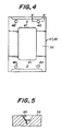
- An upper surface 39 of each of the first and second frame bases 37 and 38 is rectangular as shown in Figs. 4 and 5 and formed at four corners with fitting apertures 40 for positioning, each of which is frustoconical, tapered downwardly or inwardly.
- the upper surface 39 of each frame base 37 or 38 is further formed at forward and rearward ends with connecting openings 41 to be connected to a pressurized air source through hoses and selector valves (not shown) for driving (pneumatically in this embodiment) an annular member to be described hereinafter.
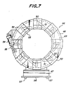
- each of the annular members 46 comprises a box-shaped framework 47, an annular body 48 whose lower end is fixed to the framework 47 and a cam ring 49 concentric to and rotatably supported by the annular body 48.
- the annular body 48 is formed with a plurality of slits 50 extending in radial directions and spaced circumferentially equidistant one relative to the other.
- the cam ring 49 is formed with a plurality of inclined slits 51 spaced circumferentially equidistant one relative to the other.
- a plurality of chuck segments 52 are supported movably in the radial directions by the annular body 48 and spaced circumferentially equidistant one relative to the other. These chuck segments 52 are connected to rollers (not shown) inserted in the slits 50 and 51. As a result, when the cam ring 49 is rotated, the chuck segments 52 are moved in the radial directions in synchronism with each other so that a chuck 53 consisting of the chuck segments 52 is expanded or contracted to increase or decrease its diameter.
- a bottom surface 56 of the framework 47 for each of the annular members 46 is rectangular similar to the upper surface 39 and formed at four corners with fitting protrusions 57 which are frustoconical, tapered toward their ends and in snugly fitted relations with the fitting apertures 40.
- fitting protrusions 57 are fitted in the fitting apertures 40 of the first and second frame bases 37 and 38, respectively, to position the annular members 46 relative to the first and second frame bases 37 and 38 with high accuracy.
- the bottom surface 56 of the framework 47 is formed in forward and rearward ends with connecting openings 58 which are connected to the connecting openings 41 through couplers (not shown) when the annular member 46 is mounted on the first or second frame base 37 or 38.
- These connecting openings 58 and the cylinders 54 are connected to each other through passages and hoses (not shown).
- pressurized air as driving power is supplied from the pressurized air source into the cylinder 54 or exhausted from the cylinder 54.
- the chuck 53 is expanded or contracted.
- the band U as a cylindrical member formed on the first or second forming drum 26 or 27 can be grasped on its outside by the chuck 53.
- a spring 60 as a retaining mechanism is provided in the cylinder 54 for urging the piston 59 and the piston rod 55 in an extending direction (Fig. 6).
- the spring 60 serves to urge the piston rod 55 and the chuck 53 against the band U so as to maintain the chuck in band grasping condition, thereby preventing the band U from shifting in position or the like in transferring the annular member 46.
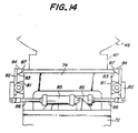
- a tire forming unit 65 arranged forward of the second band forming unit 21.
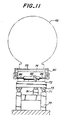
- the tire forming unit 65 includes driving means 66 and a tire forming drum 67 as another forming drum extending from the driving means 66 in the left direction viewed in Fig. 1.
- the tire forming drum 67 is rotatable about an axis in parallel with the second band forming drum 27 and has a bladder 68 (Fig. 10) deformable into a toroid shape by the driving means 66.
- the band U and a green case G transferred by a loader (not shown) are combined to form a green tire T on the tire forming drum 67.
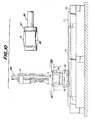
- a base 70 On the left side of the tire forming unit 65 is arranged a base 70 extending in parallel with the base 8. On the base 70 are arranged a pair of rails 71 extending straight along the base 70. A carriage 72 is arranged slidably on the rails 71 and has slide bearings 73 mounted on an underside of the carriage 72 and slidably engaging the rails 71. Onto the carriage 72 is fixed a third frame base 74 as a further frame base whose upper surface 75 is formed with fitting apertures 76 and connecting openings 77 shown in Figs. 12 and 13 similar to the fitting apertures 40 and connecting openings 41 in the frame bases 37 and 38. These connecting openings 77 are connected through couplers to connecting openings 58 of the annular member 46 for supplying pressurized air.
- the annular member 46 can be arranged on the third frame base 74.
- brackets 81 are fixed to forward and rearward end faces of the third frame base 74, respectively.
- the brackets 81 rockably support the centers of rocking arms 82 having upper ends to which are fixed pressing pieces 84 having inclined surfaces 83.
- Cylinders 85 have head ends connected to the carriage 72 and piston rods 86 whose rod ends are connected to lower ends of the rocking arms 82.
- the piston rods 86 of the cylinders 85 are extended to rock the rocking arms 82 into upstanding positions, the inclined surfaces 83 of the pressing pieces 84 are brought into surface contact with inclined surfaces 87 formed at angles substantially equal to those of the inclined surfaces 83 on the framework 47 of the annular member 46. Consequently, the annular member 46 is locked to the third frame base 74 by wedge action of these inclined surfaces.
- a rodless cylinder 91 is connected to the base 70 and extending therealong.
- the carriage 72 is connected to a movable block (not shown) of the rodless cylinder 91.
- the carriage 72 and the third frame base 74 are moved straight in a horizontal plane guided by the rails 71 along the axis of the tire forming drum 67 toward and away from the tire forming drum 67.
- a base 96 extending in 26 parallel with the base 8.
- a pair of rails 97 are arranged on the base 96 and extending therealong.
- a rectangular movable trolley 98 is movable on the rails 97 with the aid of a plurality of wheels 99 mounted on an underside of the trolley 98 and rolling contacting the rails 97.
- a cylinder 103 extends along the base 96 and has a head end connected to the base 96 and a piston rod 104 whose rod end is connected to the movable trolley 98. When the cylinder 103 is actuated, the movable trolley 98 is moved in a horizontal plane guided by the straight rails 97 through a distance equal to the distance L.
- a pair of transfer assemblies 106 and 107 are arranged on the movable trolley 98 and spaced the distance L from each other in the longitudinal direction and are movable in traverse directions together with the annular members 46 grasped thereby.
- the transfer assemblies 106 and 107 are raised and lowered by a pair of lift assemblies 108 and 109 through a some distance, in more detail a distance slightly longer than the extending distance of the fitting protrusions 57.
- the transfer assemblies 106 and 107 have rectangular base plates 110, respectively, and the lift assemblies 108 and 109 have pairs of eccentric rods 115 interposed between the these base plates 110 and the movable trolley 98. These eccentric rods 115 horizontally extend in the longitudinal directions of the movable trolley 98 and eccentrically rotate about axes positioned spaced from sectional centers of the eccentric rods 115. When the eccentric rods 115 are rotated, the transfer assemblies 106 and 107 are raised or lowered.
- two pairs of brackets 125 are spaced in a longitudinal direction of the movable trolley 98 and mounted thereon.
- Horizontal rails 126 having U-shaped sections and extending in width directions of the movable trolley 98 are fixed to inner surfaces of each pair of the brackets 125 in opposition to each other, respectively.
- Center arms 127 are arranged between the rails 126 and extend in parallel therewith. Lengths of the center arms 127 are substantially equal to a width of the movable trolley 98.
- a plurality of rollers 128 are rotatably supported on outer surfaces of the center arms 127 so as to be in rolling contact with the rails 126.
- the center arms 127 are movable guided by the rails 126 in a horizontal plane in traverse directions.
- Onto each of the base plates 110 is mounted a motor 131 with a reduction device whose output shaft 132 is provided with an external gear 130 fixed thereto.
- Transmission shafts 133 are rotatably supported by bearings (not shown) provided on the base plate 110.
- An external gear 134 to be in mesh with the external gear 130 is fixed to each of the transmission shafts 133.
- a rack 135 extending along one of the center arms 127 is secured thereto and in mesh with the pinion 136 fixed to the transmission shaft 133.
- the center arms 127 are moved in the traverse directions.
- a forward arm 138 is interposed between each pair of center arms 127 and extending therealong and is formed with guide grooves 139 extending in a longitudinal direction of the forward arm 138.
- a plurality of rollers 140 are rotatably supported on inner surfaces of the center arms 127 and are inserted in the guide grooves 139 so as to be in rolling contact therewith.
- a chain 141 has one end connected to the center arm 127 and the other end connected to the forward arm 138.
- a mid portion of the chain 141 extends around and in mesh with a sprocket 142 rotatably supported by a shaft 143 which is in turn supported by the center arms 127.
- Grasping pawls 152 are rotatably supported through pins 151 at forward and rearward ends of each of the forward arms 138.
- Each of the forward arms 138 is provided with a cylinder 153 whose head end is connected to one end of the one grasping pawl 152 and rod end of a piston rod 154 of the cylinder 153 is connected to one end of the other grasping pawl 152.
- the grasping pawls 152 are rotated in synchronism with each other.
- Each of the grasping pawls 152 is formed in the other end with a recess 155 for receiving a corner of the framework 47 of the annular member 46.
- the base plates 110, the center arms 127, the motors 131 with the reduction devices, the forward arms 138, the chains 141, the grasping pawls 152 and the cylinders 153 form as a whole the transfer assemblies 106 and 107.
- the movable trolley 98, the transfer assemblies 106 and 107 and the lift assemblies 108 and 109 form as a whole a transfer mechanism 161 which is provided between the first, second and third frame bases 37, 38 and 74 for transferring the annular members 46 grasping bands U from the first and second frame bases 37 and 38 to the third frame base 74 or transferring the annular member 46 having no tire member from the third frame base 74 to the first and second frame bases 37 and 38.
- first, second and third frame bases 37, 38 and 74 and the transfer mechanism 161 form as a whole taking-out means 162 for removing formed band U from the first and second band forming drums 26 and 27 and transferring them to the tire forming drum 67.
- the taking-out means 162 takes formed bands U out of the first and second band forming drums 26 and 27, alternately, and transfers the bands U to one tire forming drum 67 in this manner. Therefore, the first and second band forming drums 26 and 27 of long forming cycle times and the tire forming drum 67 of short forming cycle time can be operated with high efficiency or with less loss time. Moreover, even if any one of the band forming drums 26 and 27 is failed, the forming operation can be continued without stopping the entire apparatus.
- first and second band forming drums 26 and 27 The operation of the apparatus of the above embodiment of the invention will be explained hereinafter. First, the operations in connection with the first and second band forming drums 26 and 27 will be explained. It is now assumed that the first band forming drum 26 is positioned at the supply position C and does not have plies wound therearound. At this time, the second band forming drum 27 is positioned at the supply position E and has a formed band U wound therearound. At this time, moreover, the annular members 46 are not arranged on the first and second frame bases 37 and 38 yet.
- the rodless cylinder 16 is then actuated to move the first trolley 12 a distance of twice the distance L to the right viewed in Fig. 2. Consequently, the first band forming drum 26 arrives at the supply position A immediately forward of the belt ply supply means 1.
- Belt plies V1 of a predetermined kind are then supplied from the belt ply supply means 1 to the first band forming drum 26, while the first band forming drum 26 is rotated by means of the first driving means 24 so that the plies V1 are wound around the first band forming drum 26.
- the cylinder 28 is actuated to extend the piston rod so that the first band forming drum 26 is moved a distance equal to the distance L to the right.
- the first band forming drum 26 is moved to the supply position B immediately forward of the belt ply supply means 2.
- belt plies V2 of a kind different from that of the belt plies V1 are supplied from the belt ply supply means 2 to the first band forming drum 26, while the first band forming drum 26 is rotated so that the belt plies V2 are wound around the first band forming drum 26 over the belt plies V1.
- the first band forming drum 26 is successively moved to the positions A and B of the belt ply supply means 1 and 2 by the operation of the first moving means 30 so that the belt plies V1 and V2 different in kind supplied from the belt ply supply means 1 and 2 at the supply positions A and B are successively wound around the first band forming drum 26.
- the rodless cylinder 16 is operated to move the first trolley 12 a distance of twice the distance L to the left, while at the same time the cylinder 28 is operated to move the first band forming unit 20 a distance equal to the distance L to the left.
- the first band forming drum 26 with the belt plies V1 and V2 wound therearound is moved from the supply position B to the supply position C immediately forward of the first tread supply means 3.
- a tread T is then supplied from the first tread supply means 3 to the first band forming drum 26 and is further wound around the belt plies V1 and V2 on the first band forming drum 26.
- the following operation is performed simultaneously with the winding of the belt plies V1 and V2 and the tread T onto the first band forming drum 26 (forming the band U).
- the annular member 46 having no tire member is transferred to and arranged onto the second frame base 38 positioned at the taking-out position F by means of the transfer mechanism 161.
- the fitting protrusions 57 of the annular member 46 are fitted in the fitting apertures 40 of the second frame base 38 to exactly position the annular member 46 relative to the second frame base 38, and the connecting openings 41 and 58 are connected to each other so that the cylinder 54 of the annular member 46 is ready for receiving pneumatic power as the driving force.
- the piston rod of the cylinder 29 is extended to move the second band forming unit 21 to the left viewed in Fig. 1 so as to approach the annular member 46 on the second frame base 38.
- the second band forming drum 27 has moved the distance L to arrive at the taking-out position F, the movement of the second band forming drum 27 is stopped.
- the second band forming drum 27 has been loosely fitted in the annular member 46 and the band U.
- the selector valve is switched over to supply the driving force (pneumatic power) into the cylinder 54 of the annular member 46 on the second frame base 38 from the the pressurized air source through the connecting openings 41 and 58 and the hoses.
- the piston rod 55 of the cylinder 54 extends to rotate the cam ring 49 of the annular member 46 so that the chuck segments 52 move radially inwardly in synchronism with each other to reduce the diameter of the chuck 53.
- the reduction in diameter of the chuck 53 is stopped when inner circumferential surfaces of the chuck segments 52 abut against an outer circumferential surface of the band U.
- the second band forming drum 27 contracts to reduce its diameter, the band U is transferred from the second band forming drum 27 to the chuck 53 of the annular member 46.
- the piston rod of the cylinder 29 is then retracted so that the second band forming drum 27 is moved to the right to return to the supply position E.
- the annular member 46 grasping the band U on its outside is removed from the second frame base 38 by means of the transfer mechanism 161.
- the diameter of the chuck 53 is expanded to release the band U grasped thereby.
- the chuck 53 is urged against the band U with the aid of the spring 60 so that the band U is kept grasped by the chuck 53, although the annular body 46 is removed from the second frame base 38. Therefore, the band U is prevented from being released with a great certainty.
- the winding operation of the belt plies V1 and V2 and the tread T onto the first band forming drum 26 as described above is carried out simultaneously with the taking-out operation of the band U from the second band forming drum 27 with the aid of the annular member 46.
- the cycle times of the winding and taking-out operations are substantially equal to each other so that the first and second forming drums 26 and 27 scarcely cause loss time in operation.
- the rodless cylinder 17 is then actuated to move the second trolley 13 a distance of twice the distance L to the left, while the cylinder 29 is actuated to move the second band forming unit 21 a distance equal to the distance L to the left.
- the second band forming drum 27 has been moved from the supply position E to the supply position A.
- Belt plies V1 are then supplied from the belt ply supply means 1 onto the second band forming drum 27 and wound therearound, and thereafter the cylinder 29 is actuated to move the second band forming drum 27 a distance equal to the distance L to the right.
- the second band forming drum 27 has been moved from the supply position A to the supply position B.
- belt plies V2 are supplied from the belt ply supply means 2 onto the second band forming drum 27 and wound over the belt ply V1 wound thereon.
- the second band forming drum 27 is successively moved to the first and second supply positions A and B of the belt ply supply means 1 and 2, and at the respective supply positions A and B the belt plies V1 and V2 different in kind supplied from the belt ply supply means 1 and 2, respectively, are successively wound around the second band forming drum 27.
- the rodless cylinder 17 is actuated to move the second trolley 13 a distance of twice the distance L to the right so that the second band forming drum 27 is moved from the supply position B to the supply position E.
- a tread T is then supplied from the second tread supply means 4 to the second band forming drum 27, while the second band forming drum 27 is being rotated by the second driving means 25 so that the tread T is further wound around the belt plies V1 and V2 on the second band forming drum 27. In this manner, a band U is formed around the second band forming drum 27.
- the following operation is performed simultaneously with the winding of the belt plies V1 and V2 and the tread T onto the second band forming drum 27 (forming the band U).
- the annular member 46 having no tire member is transferred to and arranged onto the first frame base 37 positioned at the taking-out position D by means of the transfer mechanism 161.
- the fitting protrusions 57 of the annular member 46 are fitted in the fitting apertures 40 of the first frame base 37 to exactly position the annular member 46 relative to the first frame base 37, and the connecting openings 41 and 58 are connected to each other so that the cylinder 54 of the annular member 46 is ready for receiving the driving force (pneumatic power).
- the piston rod of the cylinder 28 is extended to move the first band forming drum 26 a distance equal to the distance L to the right so as to arrive at the taking-out position D.
- the first band forming drum 26 has been loosely fitted in the annular member 46 and the band U.
- the cylinder 54 of the annular member 46 is supplied with the pressurized air to contract the diameter of the chuck 53 so that the band U is grasped on its outside by the chuck 53.
- the first band forming drum 26 is contracted to reduce its diameter so that the band U is transferred from the first band forming drum 26 to the annular member 46.
- the cylinder 28 is then actuated to move the first band forming drum 26 a distance equal to the distance L to the left so as to return the supply position C.
- the annular member 46 grasping the band U on its outside is removed from the first frame base 37 by means of the transfer mechanism 161.
- the spring 60 keeps the chuck 53 grasping the band U. Therefore, the band U is not removed from the chuck 53 even if the annular member 46 is removed from the first frame base 37 in the same manner as above described.
- the winding operation of the belt plies V1 and V2 and the tread T onto the second band forming drum 27 is carried out simultaneously with the taking-out operation of the band U from the first band forming drum 26 with the aid of the annular member 46.
- the cycle times of the winding and taking-out operations are substantially equal to each other so that the first and second forming drums 26 and 27 scarcely cause loss time in operation.
- the operation of forming the band at the first band forming drum 26 is performed simultaneously with the operation of taking-out the formed band U from the second band forming drum 27 and the operation of forming the band at the second band forming drum 27 is performed simultaneously with the operation of taking-out the formed band U from the first band forming drum 26.
- the word “simultaneously” includes of course the case wherein cycle times of the operations are substantially equal and starting and finishing of these operations are substantially at the same time, and further includes the case wherein the cycle times of these operations are different and any operation starts or finishes earlier than the other operation does. That is, the word “simultaneously” refers to a period during which to proceed both the operations at the same time.
- the above are one cycle of operations in connection with the first and second band forming drums 26 and 27.
- the same cycles are repeated to form bands U in succession, and the formed bands U are alternately taken out from the first and second band forming drums 26 and 27.
- the numerous belt ply supply means 1 and 2 are common to the two band forming drums 26 and 27 so that the construction of the entire apparatus is simplified and small-sized. Moreover, exchanging of plies is easily effected when sizes of tires are changed.
- the remaining band forming drum and tread supply means can continue the band forming operations without being affected with the trouble. Therefore, there is no need for stopping the entire apparatus owing to the trouble of part of the apparatus.
- the belt ply supply means 1 and 2 are commonly used in this embodiment, the winding of the belt plies and the tread and taking-out of the band are simultaneously carried out so that loss time can be prevented as effectively as possible without lowering the production efficiency.
- the motor 131 with the reduction device of the transfer assembly 106 is energized so that the center arms 127 extend guided by the rails 126 toward the third frame base 74 awaiting at the position S forward of the tire forming drum 67. At this time, the forward arms 138 are moved a distance of twice the moved distance of the center arms 127 in the same direction as the moved direction of the center arms 127 with the aid of the chains 141 and the sprockets 142.
- the motor 131 with the reduction device of the transfer assembly 107 is energized so that the center arms 127 and the forward arms 138 are extended toward the second frame base 38 positioned at the taking-out position F in the same manner as the transfer assembly 106.
- the extensions of the center and forward arms 127 and 138 of the transfer assemblies 106 and 107 are stopped when the forward arms 138 arrive at positions on both sides of the third and second frame bases 74 and 38, respectively. Thereafter, the cylinders 116 of the lift assemblies 108 and 109 are operated so as to eccentrically rotate the eccentric rods 115 to lower the transfer assemblies 106 and 107 through predetermined distances. As a result, the annular member 46 grasping the band U and held by the transfer assembly 106 is arranged on the third frame base 74, whereas the annular member 46 having no tire member and held by the transfer assembly 107 is arranged on the second frame base 38.
- the fitting protrusions 57 are fitted in the fitting apertures 76 and 40, respectively, so that these annular members 46 are exactly positioned relative to the third and second frame bases 74 and 38, respectively.
- the connecting openings 58 are connected to the connecting openings 77 and 41, respectively, so that the annular bodies 46 are ready for receiving the driving force (pneumatic power).
- the cylinders 153 of the transfer assembly 106 are actuated in synchronism with each other to retract their piston rods 154.
- the grasping pawls 152 are rocked to positions in parallel with the forward arms 138 so that the four corners of the annular member 46 arranged on the third frame base 74 are disengaged from the recesses 155 of the grasping pawls 152 to release the annular member 46 from the grasping by the transfer assembly 106.
- the cylinders 85 of the third frame base 74 are actuated to extend their piston rods 86 so that the rocking arms 82 are rocked into upstanding positions.
- the pressing pieces 84 are brought into surface contact with the inclined surfaces 87 of the framework 47 of the annular member 46 so that the framework 47 is urged against the third frame base 74 by the wedge action of the inclined surfaces, with the result that the annular member 46 is positioned relative to and locked to the third frame base 74.
- the band U grasped by the annular member 46 becomes exactly coaxial with the tire forming drum 67.
- the motor 131 with the reduction device of the transfer assembly 106 is then actuated to retract the center and forward arms 127 and 138 to positions immediately above the base plate 110 in order to avoid any interference with the movement of the annular member 46.
- the rodless cylinder 91 is actuated to move the trolley 72, the third frame base 74 and the annular member grasping the band U along the rails 71 to the right to a position between the tire forming drum 67 and the driving means 66.
- a cylindrical green case G is transferred to the tire forming drum 67 by means of a loader (not shown) and arranged around the forming drum 67.
- the rodless cylinder 91 is actuated to move the trolley 72, the third frame base 74 and the annular member 46 to the left so that the tire forming drum 67 is loosely fitted in the annular member 46 and the band U.
- the bladder 68 of the tire forming drum 67 expands to increase its diameter to deform the the green case G into a toroid shape.
- the radially outer circumferential surface of the green case G is pressed against the radially inner circumferential surface of the band U grasped by the annular member 46 to form a green tire.
- the cylinder 54 of the annular member 46 is then supplied with pressurized air from the pressurized air source to retract the piston rod 55 so that the chuck 53 is expanded to increase its diameter, with the result that the formed green tire is transferred from the annular member 46 to the tire forming drum 67.
- the rodless cylinder 91 is actuated to move the trolley 72, the third frame base 74 and the annular member 46 having no tire member to the left to the poising position S.
- the formed green tire is removed from the tire forming drum 67 and is transferred to the next station for the next process by the loader.
- the motor 131 with the reduction device of the transfer assembly 106 is then energized to extend the center and forward arms 127 and 138 of the transfer assembly 106 toward the third frame base 74. The movement of these arms is stopped when the forward arms 138 arrive at the annular member 46 on the third frame base 74. Thereafter, the piston rod 154 of the cylinder 153 of the transfer assembly 106 is extended to rock the gasping pawls 152 into positions perpendicular to the forward arms 138. As a result, the four corners of the annular member 46 arranged on the third frame base 74 enter the recesses 155 of the grasping pawls 152 so that the annular member 46 is held by the transfer assembly 106. The cylinder 85 of the third frame base 74 is then actuated to rock the rocking arms 82 into horizontal positions so that the positioning and locking of the annular member 46 relative to the third frame base 74 are released.
- the band U formed on the second band forming drum 27 is supplied to the annular member 46 arranged on the second frame base 38 and grasped by the annular member 46 as above described. At this time, the center and forward arms 127 and 138 of the transfer assembly 107 are maintained in the extended condition.
- cylinders 116 of the lift assemblies 108 and 109 are actuated so as to rotate the eccentric rods 115 to raise the transfer assemblies 106 and 107 grasping the annular members, respectively, through predetermined distances. Therefore, the fitting protrusions 57 of the respective annular members 46 leave the fitting apertures 76 and 40, whereas the connecting openings 58 are disengaged from the connecting openings 77 and 41.
- the motors 131 with the reduction devices of the transfer assemblies 106 and 107 are then energized, the center and forward arms 127 and 138 are retracted together with the annular members 46 grasped thereby to positions immediately above the base plate 110.
- the cylinder 103 is then actuated to move the movable trolley 98 along the rails 97 to the left limit position.
- the motors 131 with the reduction devices of the transfer assemblies 106 and 107 are 10 energized to extend the center and forward arms 127 and 138 of the transfer assembly 106 grasping the annular member 46 having no tire member toward the first frame base 37 positioned at the taking-out position, while the center and forward arms 127 and 138 of the transfer assembly 107 grasping the band U are extended toward the third frame base 74.
- the extensions of the center and forward arms 127 and 138 of the transfer assemblies 106 and 107 are stopped when the forward arms 138 arrive onto both sides of the third and first frame bases 74 and 37.
- the cylinders 116 of the lift assemblies 108 and 109 are then actuated to lower the transfer assemblies 106 and 107 through predetermined distances.
- the annular member 46 grasping the band U is arranged on the third frame base 74, while the annular member 46 having no tire member is arranged on the first frame base 37.
- the annular members 46 are exactly positioned relative to the third and first frame bases 74 and 37, respectively.
- the connecting openings 58 have been connected to the connecting openings 77 and 41, respectively, the annular members 46 are ready for receiving the driving force.
- the cylinder 153 of the transfer assembly 107 is actuated to release the grasping pawls 152 from the corners of the annular member 46 arranged on the third frame base 74. As a result, the annular member 46 is released from the holding of the transfer assembly 107. Thereafter, the cylinder 85 of the third frame base 74 is actuated to urge the framework 47 against the third frame base 74 by the wedge action of the pressing pieces 84 so that the annular member 46 is positioned relative to and locked against the third frame base 74. The motor 131 with the reduction device of the transfer assembly 107 is then energized to retract the center and forward arms 127 and 138 to positions immediately above the base plate 110 in order to avoid any interference with the movement of the annular member 46.
- the rodless cylinder 91 is actuated to move the trolley 72, the third frame base 74 and the annular member 46 grasping the band U to the right to positions between the tire forming drum 67 and the driving means 66.
- a cylindrical green case G is mounted on the tire forming drum 67 by the loader (not shown).
- the rodless cylinder 91 is then actuated to move the trolley 72, the third frame base 74 and the annular member 46 to the left so that the tire forming drum 67 is loosely fitted in the annular member 46 and the band U.
- the bladder 68 of the tire forming drum 67 is then expanded to increase its diameter so that the green 10 case G is deformed into a toroid shape so as to press the green case G against the band U to form a green tire.
- the chuck 53 of the annular member 46 is expanded to increase its diameter so that the formed green tire is transferred from the annular member 46 to the tire forming drum 67.
- the rodless cylinder 91 is actuated to move the trolley 72, the third frame base 74 and the annular member 46 having no tire member to the left to the poising position S.
- the formed green tire is removed from the tire forming drum 67 in sequence with contraction of the bladder 68 and is transferred by the loader to a next station for a next process.
- the motor 131 with the reduction device of the transfer assembly 107 is then energized to extend the center and forward arms 127 and 138 until the forward arms 138 arrive at the annular member 46 on the third frame base 74.
- the cylinder 153 of the transfer assembly 107 is then actuated to rock the grasping pawls 152 so that the annular member 46 is held by the transfer assembly 107.
- the cylinder 85 of the third frame base 74 is actuated to release the positioning and locking of the annular member 46 relative to the third frame base 74.
- the band U formed on the first band forming drum 26 is supplied to and grasped by the annular member 46 arranged on the first frame base 37 as above described. At this time, the center and forward arms 127 and 138 of the transfer assembly 106 are maintained in extended conditions.
- the lift assemblies 108 and 109 are operated to raise the transfer assemblies 106 and 107 grasping the annular members, respectively, through predetermined distances.
- the fitting protrusions 57 of the respective annular members 46 are removed from the fitting apertures 76 and 40, while the connecting openings 58 are disengaged from the connecting openings 77 and 41.
- the motors 131 with the reduction devices of the transfer assemblies 106 and 107 are energized to retract the center and forward arms 127 and 138 together with the annular members 46 grasped thereby to the positions immediately above the base plate 110.
- the cylinder 103 is then actuated to move the movable trolley 98 along the rails 97 to the right limit position.
- the forming of the bands at the first and second band forming drums 26 and 27, the taking-out and transferring of the bands by the taking-out means 162 and the forming of the green tires at the tire forming drum 67 are simultaneously carried out.
- the one tire forming drum 67 is provided commonly to the two band forming drums 26 and 27 so that the entire apparatus can be simplified in construction and small-sized.
- the annular member 46 having only a performance grasping a band U and small-sized and light weight can be removed from the first and second frame bases 37 and 38 and transferred to the third frame base 74, the band U can be readily transferred between the first and second band forming drums 26 and 27 and the tire forming drum 67, even if these drums are not coaxial with each other.
- first and second band forming drums 26 and 27 are moved toward and away from the first and second frame bases 37 and 38.
- the first and second frame bases 37 and 38 may be moved toward and away from the first and second band forming drums 26 and 27.
- the spring 60 is used in order to maintain the band grasped by the chuck of the annular member.
- brake means additionally provided on the cylinder may be used instead of the spring.
- the invention provides a tire building apparatus which is simple in construction and small-sized and which makes it possible to form bands with high efficiency. Moreover, with two forming drums between which cylindrical members such as belts and tread bands are transferred, even if these forming drums are not coaxial with each other or there is any obstruction between the forming drums, the cylindrical members can be transferred between the drums with high efficiency, keeping the accuracy of the members, notwithstanding the small-sized and simply constructed apparatus according to the invention.
Landscapes
- Engineering & Computer Science (AREA)
- Mechanical Engineering (AREA)
- Tyre Moulding (AREA)
Applications Claiming Priority (4)
| Application Number | Priority Date | Filing Date | Title |
|---|---|---|---|
| JP217980/89 | 1989-08-24 | ||
| JP1217980A JPH0381133A (ja) | 1989-08-24 | 1989-08-24 | 円筒体の移送装置 |
| JP1217979A JPH0381132A (ja) | 1989-08-24 | 1989-08-24 | タイヤ成型方法および装置 |
| JP217979/89 | 1989-08-24 |
Publications (2)
| Publication Number | Publication Date |
|---|---|
| EP0414554A2 true EP0414554A2 (fr) | 1991-02-27 |
| EP0414554A3 EP0414554A3 (en) | 1992-10-28 |
Family
ID=26522328
Family Applications (1)
| Application Number | Title | Priority Date | Filing Date |
|---|---|---|---|
| EP19900309286 Withdrawn EP0414554A3 (en) | 1989-08-24 | 1990-08-23 | Tire building method and apparatus |
Country Status (2)
| Country | Link |
|---|---|
| US (1) | US5213651A (fr) |
| EP (1) | EP0414554A3 (fr) |
Cited By (4)
| Publication number | Priority date | Publication date | Assignee | Title |
|---|---|---|---|---|
| EP0503533A1 (fr) * | 1991-03-14 | 1992-09-16 | Continental Aktiengesellschaft | Procédé et dispositif de fabrication de bandes de roulement et de ceintures pour pneumatiques de véhicules |
| EP0503532A1 (fr) * | 1991-03-14 | 1992-09-16 | Continental Aktiengesellschaft | Procédé et dispositif de fabrication de bandes de roulement et de ceintures pour pneumatiques de véhicules |
| EP0597125A4 (fr) * | 1992-06-01 | 1994-11-30 | Mitsubishi Heavy Ind Ltd | Appareil de moulage de pneu. |
| EP1295699A3 (fr) * | 2001-09-21 | 2004-06-23 | The Goodyear Tire & Rubber Company | Procédé et dispositif d'alignement précis de tambours pour la confection de pneumatiques |
Families Citing this family (7)
| Publication number | Priority date | Publication date | Assignee | Title |
|---|---|---|---|---|
| JP3187954B2 (ja) * | 1992-07-21 | 2001-07-16 | 三菱重工業株式会社 | タイヤ成形システム |
| US6773530B2 (en) | 2001-09-21 | 2004-08-10 | The Goodyear Tire & Rubber Company | Method for manufacturing tires on a flexible manufacturing system |
| RU2302341C2 (ru) * | 2002-04-09 | 2007-07-10 | Матадор а.с. | Способ и установка для изготовления невулканизированных шин |
| ATE322973T1 (de) * | 2002-11-05 | 2006-04-15 | Pirelli | Verfahren und anlage zur herstellung von reifen für fahrzeugräder |
| US8171619B2 (en) * | 2008-06-02 | 2012-05-08 | Vmi Holland B.V. | Device for manufacturing a pre-assembly for a tire |
| DE102013103629A1 (de) * | 2013-04-11 | 2014-10-16 | Continental Reifen Deutschland Gmbh | Verfahren zur Herstellung eines Fahrzeugreifens |
| CN113459553B (zh) * | 2021-09-02 | 2022-02-15 | 天津赛象科技股份有限公司 | 通过仿形缠绕方式制作轮胎胎面的方法、产品、设备、终端 |
Family Cites Families (11)
| Publication number | Priority date | Publication date | Assignee | Title |
|---|---|---|---|---|
| US1964363A (en) * | 1930-07-11 | 1934-06-26 | Morgan & Wright | Method and apparatus for manufacturing tires |
| DE1579129C3 (de) * | 1964-10-03 | 1974-11-21 | Continental Gummi-Werke Ag, 3000 Hannover | Gürtelreifenaufbaumaschine |
| US3909335A (en) * | 1974-05-22 | 1975-09-30 | Gen Tire & Rubber Co | Pneumatic tire transporter |
| US4105487A (en) * | 1975-12-27 | 1978-08-08 | Bridgestone Tire Company Limited | Process of and an apparatus for producing green tires |
| US4134783A (en) * | 1976-06-16 | 1979-01-16 | The Goodyear Tire & Rubber Company | Tire building system |
| JPS57174236A (en) * | 1981-04-20 | 1982-10-26 | Mitsubishi Heavy Ind Ltd | Feeder for tire molding machine |
| JPS59202838A (ja) * | 1983-05-02 | 1984-11-16 | Bridgestone Corp | 空気タイヤ用無端状部材の移送装置 |
| JPS6078729A (ja) * | 1983-10-05 | 1985-05-04 | Bridgestone Corp | ラジアルタイヤの成形素材供給装置 |
| GB8411820D0 (en) * | 1984-05-09 | 1984-06-13 | Bates W & A Ltd | Manufacture |
| IT1203558B (it) * | 1986-05-20 | 1989-02-15 | Firestone Int Dev Spa | Metodo per la realizzazione di un pneumatico radiale di prima fase per veicoli |
| JPH02147231A (ja) * | 1988-11-29 | 1990-06-06 | Yokohama Rubber Co Ltd:The | タイヤ成形方法及びその装置 |
-
1990
- 1990-08-23 EP EP19900309286 patent/EP0414554A3/en not_active Withdrawn
- 1990-08-24 US US07/571,695 patent/US5213651A/en not_active Expired - Fee Related
Cited By (5)
| Publication number | Priority date | Publication date | Assignee | Title |
|---|---|---|---|---|
| EP0503533A1 (fr) * | 1991-03-14 | 1992-09-16 | Continental Aktiengesellschaft | Procédé et dispositif de fabrication de bandes de roulement et de ceintures pour pneumatiques de véhicules |
| EP0503532A1 (fr) * | 1991-03-14 | 1992-09-16 | Continental Aktiengesellschaft | Procédé et dispositif de fabrication de bandes de roulement et de ceintures pour pneumatiques de véhicules |
| EP0597125A4 (fr) * | 1992-06-01 | 1994-11-30 | Mitsubishi Heavy Ind Ltd | Appareil de moulage de pneu. |
| EP1295699A3 (fr) * | 2001-09-21 | 2004-06-23 | The Goodyear Tire & Rubber Company | Procédé et dispositif d'alignement précis de tambours pour la confection de pneumatiques |
| US6966958B2 (en) | 2001-09-21 | 2005-11-22 | The Goodyear Tire & Rubber Company | Precision alignment of tire building drum to automated tire building system working axis |
Also Published As
| Publication number | Publication date |
|---|---|
| US5213651A (en) | 1993-05-25 |
| EP0414554A3 (en) | 1992-10-28 |
Similar Documents
| Publication | Publication Date | Title |
|---|---|---|
| EP0414554A2 (fr) | Procédé et dispositif de fabrication de pneus | |
| CN102046361B (zh) | 用于组装轮胎的方法和设备 | |
| US4473427A (en) | Radial tire manufacture apparatus | |
| EP1547757B1 (fr) | Tambour de moulage de pneumatique et procede de moulage de pneumatique | |
| EP0997263A2 (fr) | Procédé et dispositif pour la fabrication de pneumatiques | |
| EP0417991A2 (fr) | Dispositif pour la mise en forme d'un élément cylindrique | |
| US5413653A (en) | Apparatus and method for forming a green tire | |
| MXPA05005495A (es) | Sistema de construccion de neumatico, sistema de fabricacion de neumatico que tiene el mismo y metodo de fabricacion de neumatico. | |
| US5141587A (en) | Two stage tire building apparatus | |
| EP0747207B1 (fr) | Machine de confection de pneumatiques | |
| US3676262A (en) | Tire building drum having a magnetized surface | |
| US3740292A (en) | Tire building machine | |
| EP0358435B1 (fr) | Dispositif pour la fabrication de pneumatiques comprenant un dispositif de transfert pour éléments constitutifs de pneus. | |
| EP0516358B1 (fr) | Procédé et dispositif de maintien d'un talon | |
| US3687756A (en) | Method and apparatus for stripping flexible article from a building drum | |
| JPH1158385A (ja) | タイヤ製造用内型の取外し装置 | |
| US3909336A (en) | Apparatus for successively supplying endless tire bands to a tire carcass producing equipment | |
| US5186778A (en) | Cylindrical member removal and transfer method | |
| EP1733841B1 (fr) | Méthode et dispositif pour faire tourner un chariot par pilotage et système de moulage de pneu utilisant la méthode et le dispositif | |
| EP0510192A1 (fr) | Appareil et procede de confection de pneu cru | |
| CN106457713A (zh) | 用于构建轮胎的工艺和设备 | |
| US5433814A (en) | Green tire building apparatus | |
| EP0340146A2 (fr) | Procédé et dispositif de fabrication de pneus | |
| JPH0381132A (ja) | タイヤ成型方法および装置 | |
| JP3181180B2 (ja) | タイヤ加硫設備 |
Legal Events
| Date | Code | Title | Description |
|---|---|---|---|
| PUAI | Public reference made under article 153(3) epc to a published international application that has entered the european phase |
Free format text: ORIGINAL CODE: 0009012 |
|
| 17P | Request for examination filed |
Effective date: 19901227 |
|
| AK | Designated contracting states |
Kind code of ref document: A2 Designated state(s): DE ES FR GB IT |
|
| PUAL | Search report despatched |
Free format text: ORIGINAL CODE: 0009013 |
|
| AK | Designated contracting states |
Kind code of ref document: A3 Designated state(s): DE ES FR GB IT |
|
| 17Q | First examination report despatched |
Effective date: 19941010 |
|
| STAA | Information on the status of an ep patent application or granted ep patent |
Free format text: STATUS: THE APPLICATION IS DEEMED TO BE WITHDRAWN |
|
| 18D | Application deemed to be withdrawn |
Effective date: 19950221 |