EP0414565A2 - Tragbarer graphischer Rechner - Google Patents
Tragbarer graphischer Rechner Download PDFInfo
- Publication number
- EP0414565A2 EP0414565A2 EP90309327A EP90309327A EP0414565A2 EP 0414565 A2 EP0414565 A2 EP 0414565A2 EP 90309327 A EP90309327 A EP 90309327A EP 90309327 A EP90309327 A EP 90309327A EP 0414565 A2 EP0414565 A2 EP 0414565A2
- Authority
- EP
- European Patent Office
- Prior art keywords
- image data
- tablet
- video signal
- picture
- coordinates
- Prior art date
- Legal status (The legal status is an assumption and is not a legal conclusion. Google has not performed a legal analysis and makes no representation as to the accuracy of the status listed.)
- Granted
Links
Images




Classifications
-
- A—HUMAN NECESSITIES
- A63—SPORTS; GAMES; AMUSEMENTS
- A63F—CARD, BOARD, OR ROULETTE GAMES; INDOOR GAMES USING SMALL MOVING PLAYING BODIES; VIDEO GAMES; GAMES NOT OTHERWISE PROVIDED FOR
- A63F13/00—Video games, i.e. games using an electronically generated display having two or more dimensions
- A63F13/40—Processing input control signals of video game devices, e.g. signals generated by the player or derived from the environment
- A63F13/42—Processing input control signals of video game devices, e.g. signals generated by the player or derived from the environment by mapping the input signals into game commands, e.g. mapping the displacement of a stylus on a touch screen to the steering angle of a virtual vehicle
- A63F13/426—Processing input control signals of video game devices, e.g. signals generated by the player or derived from the environment by mapping the input signals into game commands, e.g. mapping the displacement of a stylus on a touch screen to the steering angle of a virtual vehicle involving on-screen location information, e.g. screen coordinates of an area at which the player is aiming with a light gun
-
- A—HUMAN NECESSITIES
- A63—SPORTS; GAMES; AMUSEMENTS
- A63F—CARD, BOARD, OR ROULETTE GAMES; INDOOR GAMES USING SMALL MOVING PLAYING BODIES; VIDEO GAMES; GAMES NOT OTHERWISE PROVIDED FOR
- A63F13/00—Video games, i.e. games using an electronically generated display having two or more dimensions
- A63F13/20—Input arrangements for video game devices
- A63F13/21—Input arrangements for video game devices characterised by their sensors, purposes or types
- A63F13/214—Input arrangements for video game devices characterised by their sensors, purposes or types for locating contacts on a surface, e.g. floor mats or touch pads
- A63F13/2145—Input arrangements for video game devices characterised by their sensors, purposes or types for locating contacts on a surface, e.g. floor mats or touch pads the surface being also a display device, e.g. touch screens
-
- A—HUMAN NECESSITIES
- A63—SPORTS; GAMES; AMUSEMENTS
- A63F—CARD, BOARD, OR ROULETTE GAMES; INDOOR GAMES USING SMALL MOVING PLAYING BODIES; VIDEO GAMES; GAMES NOT OTHERWISE PROVIDED FOR
- A63F13/00—Video games, i.e. games using an electronically generated display having two or more dimensions
- A63F13/90—Constructional details or arrangements of video game devices not provided for in groups A63F13/20 or A63F13/25, e.g. housing, wiring, connections or cabinets
-
- A—HUMAN NECESSITIES
- A63—SPORTS; GAMES; AMUSEMENTS
- A63F—CARD, BOARD, OR ROULETTE GAMES; INDOOR GAMES USING SMALL MOVING PLAYING BODIES; VIDEO GAMES; GAMES NOT OTHERWISE PROVIDED FOR
- A63F13/00—Video games, i.e. games using an electronically generated display having two or more dimensions
- A63F13/90—Constructional details or arrangements of video game devices not provided for in groups A63F13/20 or A63F13/25, e.g. housing, wiring, connections or cabinets
- A63F13/92—Video game devices specially adapted to be hand-held while playing
-
- G—PHYSICS
- G06—COMPUTING OR CALCULATING; COUNTING
- G06F—ELECTRIC DIGITAL DATA PROCESSING
- G06F3/00—Input arrangements for transferring data to be processed into a form capable of being handled by the computer; Output arrangements for transferring data from processing unit to output unit, e.g. interface arrangements
- G06F3/01—Input arrangements or combined input and output arrangements for interaction between user and computer
- G06F3/048—Interaction techniques based on graphical user interfaces [GUI]
- G06F3/0484—Interaction techniques based on graphical user interfaces [GUI] for the control of specific functions or operations, e.g. selecting or manipulating an object, an image or a displayed text element, setting a parameter value or selecting a range
-
- G—PHYSICS
- G06—COMPUTING OR CALCULATING; COUNTING
- G06F—ELECTRIC DIGITAL DATA PROCESSING
- G06F3/00—Input arrangements for transferring data to be processed into a form capable of being handled by the computer; Output arrangements for transferring data from processing unit to output unit, e.g. interface arrangements
- G06F3/01—Input arrangements or combined input and output arrangements for interaction between user and computer
- G06F3/048—Interaction techniques based on graphical user interfaces [GUI]
- G06F3/0484—Interaction techniques based on graphical user interfaces [GUI] for the control of specific functions or operations, e.g. selecting or manipulating an object, an image or a displayed text element, setting a parameter value or selecting a range
- G06F3/04845—Interaction techniques based on graphical user interfaces [GUI] for the control of specific functions or operations, e.g. selecting or manipulating an object, an image or a displayed text element, setting a parameter value or selecting a range for image manipulation, e.g. dragging, rotation, expansion or change of colour
-
- A—HUMAN NECESSITIES
- A63—SPORTS; GAMES; AMUSEMENTS
- A63F—CARD, BOARD, OR ROULETTE GAMES; INDOOR GAMES USING SMALL MOVING PLAYING BODIES; VIDEO GAMES; GAMES NOT OTHERWISE PROVIDED FOR
- A63F13/00—Video games, i.e. games using an electronically generated display having two or more dimensions
- A63F13/20—Input arrangements for video game devices
- A63F13/21—Input arrangements for video game devices characterised by their sensors, purposes or types
- A63F13/213—Input arrangements for video game devices characterised by their sensors, purposes or types comprising photodetecting means, e.g. cameras, photodiodes or infrared cells
-
- A—HUMAN NECESSITIES
- A63—SPORTS; GAMES; AMUSEMENTS
- A63F—CARD, BOARD, OR ROULETTE GAMES; INDOOR GAMES USING SMALL MOVING PLAYING BODIES; VIDEO GAMES; GAMES NOT OTHERWISE PROVIDED FOR
- A63F13/00—Video games, i.e. games using an electronically generated display having two or more dimensions
- A63F13/80—Special adaptations for executing a specific game genre or game mode
-
- A—HUMAN NECESSITIES
- A63—SPORTS; GAMES; AMUSEMENTS
- A63F—CARD, BOARD, OR ROULETTE GAMES; INDOOR GAMES USING SMALL MOVING PLAYING BODIES; VIDEO GAMES; GAMES NOT OTHERWISE PROVIDED FOR
- A63F2300/00—Features of games using an electronically generated display having two or more dimensions, e.g. on a television screen, showing representations related to the game
- A63F2300/10—Features of games using an electronically generated display having two or more dimensions, e.g. on a television screen, showing representations related to the game characterized by input arrangements for converting player-generated signals into game device control signals
- A63F2300/1068—Features of games using an electronically generated display having two or more dimensions, e.g. on a television screen, showing representations related to the game characterized by input arrangements for converting player-generated signals into game device control signals being specially adapted to detect the point of contact of the player on a surface, e.g. floor mat, touch pad
- A63F2300/1075—Features of games using an electronically generated display having two or more dimensions, e.g. on a television screen, showing representations related to the game characterized by input arrangements for converting player-generated signals into game device control signals being specially adapted to detect the point of contact of the player on a surface, e.g. floor mat, touch pad using a touch screen
-
- A—HUMAN NECESSITIES
- A63—SPORTS; GAMES; AMUSEMENTS
- A63F—CARD, BOARD, OR ROULETTE GAMES; INDOOR GAMES USING SMALL MOVING PLAYING BODIES; VIDEO GAMES; GAMES NOT OTHERWISE PROVIDED FOR
- A63F2300/00—Features of games using an electronically generated display having two or more dimensions, e.g. on a television screen, showing representations related to the game
- A63F2300/10—Features of games using an electronically generated display having two or more dimensions, e.g. on a television screen, showing representations related to the game characterized by input arrangements for converting player-generated signals into game device control signals
- A63F2300/1087—Features of games using an electronically generated display having two or more dimensions, e.g. on a television screen, showing representations related to the game characterized by input arrangements for converting player-generated signals into game device control signals comprising photodetecting means, e.g. a camera
-
- A—HUMAN NECESSITIES
- A63—SPORTS; GAMES; AMUSEMENTS
- A63F—CARD, BOARD, OR ROULETTE GAMES; INDOOR GAMES USING SMALL MOVING PLAYING BODIES; VIDEO GAMES; GAMES NOT OTHERWISE PROVIDED FOR
- A63F2300/00—Features of games using an electronically generated display having two or more dimensions, e.g. on a television screen, showing representations related to the game
- A63F2300/20—Features of games using an electronically generated display having two or more dimensions, e.g. on a television screen, showing representations related to the game characterised by details of the game platform
- A63F2300/204—Features of games using an electronically generated display having two or more dimensions, e.g. on a television screen, showing representations related to the game characterised by details of the game platform the platform being a handheld device
-
- A—HUMAN NECESSITIES
- A63—SPORTS; GAMES; AMUSEMENTS
- A63F—CARD, BOARD, OR ROULETTE GAMES; INDOOR GAMES USING SMALL MOVING PLAYING BODIES; VIDEO GAMES; GAMES NOT OTHERWISE PROVIDED FOR
- A63F2300/00—Features of games using an electronically generated display having two or more dimensions, e.g. on a television screen, showing representations related to the game
- A63F2300/80—Features of games using an electronically generated display having two or more dimensions, e.g. on a television screen, showing representations related to the game specially adapted for executing a specific type of game
Definitions
- This invention relates to portable graphic computer apparatus.
- an image forming apparatus has been proposed in which a tablet having, for example, a coordinates detecting means or apparatus, a personal computer having software for processing inputted coordinates, and a television monitor for displaying a video signal generated by the personal computer, are combined to display a locus drawn on the tablet on a picture screen of the television monitor.
- the picture displayed on the monitor can be corrected with ease, and the user can draw pictures freely over and over.
- the tablet having the coordinates detecting means and the personal computer having the predetermined software are independently provided as described above, the overall arrangement of the apparatus becomes large in size and the interconnection thereof becomes complicated. This results in the disadvantage that children cannot use the apparatus with ease.
- the colours of, for example, a picture displayed on the picture screen of the television monitor must be changed between a group of, for example, 10 different colours, and various functions such as an eraser function and the like must additionally be provided.
- various functions such as an eraser function and the like must additionally be provided.
- Preferred embodiments of the invention described in detail below provided an improved portable graphic computer apparatus which can eliminate or at least reduce at least some of the above-mentioned shortcomings and disadvantages encountered with the prior art. More specifically, substantially the entire apparatus (with the possible exception of the display means) is accommodated within a cabinet and is simplified so that the apparatus is highly suited to being used by children. Also, the mechanical construction can be simplified in arrangement and other functions can be extended additionally. Further, if, as in one embodiment, the display means is mounted on the cabinet, the overall arrangement can be even more simplified, and a coordinate entry portion and a video image display portion can be provided close to each other, thus making the apparatus more useful.
- an alarm sound is generated so that the user is warned not to inadvertently leave a power switch of the apparatus in its ON state
- demonstration video data is formed after a predetermined period of time so that the apparatus is suitable for being exhibited in a shop for demonstration purposes
- a tracing sheet can be provided on the tablet with ease; and the tracing sheet can be used by children to perform a kind of learning process so that use of the apparatus is not limited to drawing pictures.
- FIG. 1 shows the overall system arrangement of a portable graphic computer apparatus according to a first embodiment.
- the apparatus comprises a portable graphic computer 1 and a monitor 2 having a video signal input terminal.
- a video signal output terminal (described below) of the graphic computer 1 and the video signal input terminal of the monitor 2 are coupled via a video cable 3.
- a cabinet of the graphic computer 1 is formed of an upper casing 4 and a lower casing 5.
- a power switch 6, a clear button 7, and a sound emanating portion 9 which covers a speaker are provided on a right end portion of the upper casing 4, and executing buttons 8A and 8B are provided on two side end portions of the upper casing 4.
- the power switch 6, clear button 7 and executing buttons 8A, 8B are respective independent mechanical switches.
- a rectangular cut-away or recessed portion 4a is formed through a centre portion of the upper casing 4, and a tablet 10 is provided beneath the cut-away portion 4a to act as a coordinate input surface of a pressure sensitive type position sensing means or apparatus.
- Slots 4b, 4c, 4d and 4e are formed through the cut-away portion 4a at portions where the cut-away portion 4a contacts the tablet 10, as shown in Figure 1. As described below, the slots 4b to 4e can be used to attach a tracing sheet to the tablet 10.
- a pen-shaped cursor 21 is displayed on a picture screen 2a of the monitor 2, and the cursor 21 moves in tandem with the locus of the pen, fingertip or the like to display the locus as an image. Accordingly, the cursor 21 is displayed only during a period in which the user touches the tablet 10 with the accessory pen 11 or fingertip.
- a respective executing button 8A, 8B is provided at each side of the tablet 10 so that both left-handed and right-handed children can operate the graphic computer 1 with ease.
- the clear button 7 is depressed, the video image on the picture screen 2a will be erased completely and the graphic computer 1 stands by in a picture drawing mode.
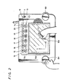
- the coordinate input surface of the tablet 10 is, as shown in Figure 2, divided into a picture-drawing area 10a and a menu selecting area 10c, and a portion (hatched area in Figure 2) of the picture-drawing area 10a encircled by a bracket and represented by solid circles at a predetermined pitch forms a picture-making area 10b.
- the aspect ratio of the picture-making area 10b is made coincident with the aspect ratio (3:4) of the picture screen of a standard monitor.
- a pixel ratio that is a ratio between resolution in the longitudinal direction (Y-direction) and resolution in the lateral direction (X-direction) of the input coordinates of the tablet 10 is made coincident with the ratio of pixels of the standard monitor. Therefore, in this embodiment, there is the advantage that, if the user draws a locus of a circle on the picture-making area 10b precisely, a picture of a circle is also accurately displayed on the picture screen 2a of the monitor 2.
- the menu selecting area 10c of the tablet 10 is divided to provide a colour selecting area 12 and a tool selecting area 13.
- the upper casing 4 has twelve round bores or openings 14 at the colour selecting area 12, and six openings or slots 15 to 20 at the tool selecting area 13. If the user lightly touches the tablet 10 through one of the twelve round openings 14 with the attachment pen 11 or the like, a respective one of twelve colours (black/blue/green/yellow/red/white etc.) will be designated. If the user lightly touches the tablet 10 through one of the six slots 15 to 20, then a respective one of five kinds of tool (fine line, bold line, brush, eraser, stamp) and a cancel function will be designated. The one of the twelve round openings 14 and six slots 15 to 20 that has been selected can be discriminated on the basis of the input coordinates to the tablet 10.
- colour, tool and cancel functions are identified on the basis of input coordinates, and thus the mechanical construction can be simplified. Further, there is the advantage that various other functions can additionally be provided simply by sub-dividing or extending the menu selecting area 10c.
- buttons 14 For convenience of explanation, the twelve round openings 14 will be referred to hereinafter as colour selecting buttons 14 and the six slots 15 to 20 will be referred to hereinafter as the fine line button 15, the bold line button 16, the brush button 17, the eraser button 18, the stamp button 19 and the cancel button 20, respectively.
- the colour selecting buttons 14 and the tool selecting buttons 15 to 20 will be collectively referred to hereinafter as the menu selecting buttons.
- the functions of the buttons 15 to 20 are as follows:
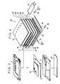
- the interior structure of the graphic computer 1 shown by way of example in Figures 1 and 2 is represented in Figures 3 and 4 (the scale of Figure 4 being enlarged with respect to Figure 3).
- the upper and lower casings 4 and 5 have sandwiched therebetween a pressure sensitive position sensing means or apparatus 23 including the tablet 10 and a printed circuit board 22.
- the lower casing 5 accommodates therein a battery cell or a rechargeable battery as a power source; and is provided with a battery cover 5a.
- the graphic computer 1 of this embodiment may be driven by an AC power source adapter or the like.
- thin strip electrodes 25 are formed on a first insulating substrate 24 at a pitch Py, and a first pressure sensitive conductive sheet 26 made of pressure sensitive conductive rubber, a conductive plate 27, a second pressure sensitive conductive sheet 28 made of pressure sensitive conductive rubber, and a second insulating substrate 29 having thin strip electrodes 30 formed on a bottom surface thereof at a pitch Px, are sequentially laminated on the first insulating substrate 24.
- the tablet 10 is mounted on the second insulating substrate 29.
- the conductive plate 27, second insulating substrate 29 and the tablet 10 are all flexible.
- the pitch Px assumes resolution in the X-direction of the input coordinates of this embodiment, and the pitch Py assumes resolution in the Y-direction thereof.
- the ratio Px/Py is made to be the same as the pixel ratio of the minimum pixels of a picture screen of a standard monitor.
- the values of the pitches or resolutions Px and Py are, for example, about 0.3 mm.
- the thin strip electrode 30 at one end or side in the lateral direction of the second insulating substrate 29 is earthed (grounded) through a switch circuit 31, while the thin strip electrode 30 at the other end or side is connected to a DC voltage source having a voltage E1 through a switch circuit 32.
- the thin strip electrodes 30 are connected sequentially by resistors 33 having the same resistance value.
- the thin strip electrode 25 at one end or side in the longitudinal direction of the second insulating substrate 24 is earthed (grounded) through a switch circuit 3in, while the thin strip electrode 25 at the other end or side is connected to a DC voltage source having a voltage E2 through a switch circuit 35.
- the thin strip electrodes 25 are connected sequentially by resistors 36 having the same resistance value.
- FIG. 5 shows the circuit arrangement of the graphic computer 1 of this embodiment.
- the circuit arrangement comprises a central processing unit (CPU) 38, a system bus 39 (which comprises a data bus, an address bus and a control bus) for the CPU 38, a read only memory (ROM) 42 storing therein a program for the CPU 38 (and video data in a demonstration mode described below), and a random access memory (RAM) 43.
- the ROM 42 and the RAM 43 are connected to the system bus 39.
- the CPU 38 is supplied with the voltages (VX, Vy) corresponding to the input coordinates (X, Y) from the coordinate detecting section 37 via an analog-to-digital (A/D) converting section 40.
- the CPU 38 identifies which one of the buttons 14 and 15 to 20 has been depressed on the basis of the coordinates (X, Y). Colour data or tool data corresponding to the identified button is written into the RAM 43. When the tool buttons 15 to 20 are selected, the CPU 38 will perform the operations corresponding to those tools.
- the CPU 38 always monitors via an input/output (I/O) interface circuit 41 whether the mechanical switches (the clear button 7 and the executing buttons 8A, 8B shown in Figure 1) are or are not operated.
- I/O input/output
- the circuit arrangement shown in Figure 5 also comprises a video processor (VDP) 44 connected to the system bus 39, a video RAM (VRAM) 45 having a capacity of 2 frames (2 pages), and an NTSC (or PAL) encoder 46.
- VDP 44 reads out data of the input coordinates (X, Y) and colour data from the RAM 43 on the basis of commands from the CPU 38 and writes colour video data into the VRAM 45 at a corresponding address thereof. Also, it reads out colour video data of 1 frame from the VRAM 45 periodically, and supplies same to the encoder 46.
- the encoder 46 converts the colour video data supplied thereto into a composite video signal CV and supplies the signal CV to a video signal output terminal 47.
- the VRAM 45 since the VRAM 45 has a storage capacity of 2 pages, in a certain procedure (one procedure, as mentioned above, means a process carried out during a period in which the executing button 8A or 8B is operated), the VDP 44 writes and reads video data in the region of, for example, the first page. In the next procedure, after completely moving the video data of the first page into the region of the second page, the VDP 44 writes and reads video data in the region of the second page.
- one procedure as mentioned above, means a process carried out during a period in which the executing button 8A or 8B is operated
- the VDP 44 again reads the video data in the first page region of the VRAM 45, and writes the video data into the first page region when the CPU 38 is supplied with coordinate data input. This means that the picture on the picture screen 2a of the monitor 2 is returned to a picture of one procedure before by operating the cancel button 20. This results in the advantage that, when the user draws a wrong picture in the picture drawing mode, the original picture can be recovered in a one-touch fashion.
- the circuit arrangement shown in Figure 5 further comprises a counter 48, an alarm circuit 49, and a speaker 50 provided for the sound emanating section 9 (see Figure 1).
- the counter 48 keeps counting clock pulses received from the CPU 38 on a clock input CK thereof and the count value can be cleared at any time by a clear pulse from the CPU 38.
- the counter 48 supplies an alarm signal AL to the CPU 38.
- the CPU 38 supplies an alarm operation command or signal to the alarm circuit 49 through the I/O interface circuit 41 in response to the alarm signal AL.
- the alarm circuit 49 comprises a timer, an oscillator, a synthesiser, a power amplifier or the like, and supplies signal in the form of a predetermined sound, melody, or message to the speaker 50 for two minutes only in response to the alarm operation command from the CPU 38.
- the counter 48, alarm circuit 49 and speaker 50 are mainly provided in order to generate an alarm sound warning the user not to leave the power switch 6 in its ON state when he has finished using the apparatus.
- the alarm circuit 49 is not limited to the alarm operation; it is utilised in a normal sound emanating operation via the interface circuit 41. For example, if the user selects any of the colour selecting buttons 14 and the tool selecting buttons 15 to 20 or the like, the alarm circuit 49 is operated so that the speaker 50 emanates a predetermined touch-sound.
- the video signal output terminal of the computer 1 is simply coupled to the video signal input terminal of the monitor 2 via the video cable 3.
- the picture screen 2a of the monitor 2 displays thereon for a predetermined period of time a demonstration display which teaches the user an example of how to use the graphic computer 1. More specifically, a pen is displayed as a cursor on the picture screen 2a to draw a predetermined picture or an eraser is displayed thereon as a cursor to erase the picture, whereby the user can understand how to use the graphic computer 1.
- a demonstration display program is written in the ROM 42 and includes colour data, tool data and a series of data of the input coordinates (X, Y) or the like.
- the CPU 38 sequentially reads these data and moves them to the RAM 43 and the VDP 44 produces video data corresponding to the data of the RAM 43, whereby a demonstration display mode is carried out as though the operator has actually drawn a locus on the tablet 10. This results in the substantial advantage that the capacity that the demonstration display program takes up in the ROM 42 can be relatively reduced.
- the graphic computer 1 of this embodiment is set into the picture drawing mode, whereby the picture displayed on the picture screen 2a of the monitor 2 is completely erased and the graphic computer is set in the standby mode awaiting input from the user.
- the locus of the cursor 21 is not displayed as a picture until the executing button 8A or 8B is operated. Accordingly, the position of the cursor can be determined precisely when the user moves, for example, from a certain stop position in the drawing to a subsequent stop position.
- the cursor 21 is shaped as a brush and, when the user lightly touches the picture making area 10b with the accessory pen 11 or the like, the user can paint out (fill in) with a designated colour the interior of a closed figure (circle, rectangle or the like) near the locus of the brush-shaped cursor within a previously drawn picture.
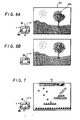
- an eraser-shaped cursor 21a is displayed in the background of a previously drawn picture on the picture screen 2a of the monitor 2 as shown in Figure 6A and, when the user depresses the executing button 8A or 8B while moving the attachment pen 11 or the like, the previously drawn picture can be partly erased. If the picture is erased too much, the picture screen 2a can be returned to the previous picture, produced before, by depressing the cancel button 20 in the menu selecting area 10c, as shown in Figure 6B.
- stamp button 19 If the user depresses the stamp button 19 in the menu selecting area 10c, several kinds of stamp characters 51 are displayed in the upper portion of the picture screen 2a of the monitor 2 as shown in Figure 7. If the user then pushes the tablet 10 at a portion corresponding to a desired one of the stamp characters 51, that character is selected as a cursor. If the user depresses the executing button 8A or 8B while lightly touching the tablet 10 with the accessory pen 11 or the like, a desired stamp character will be displayed on the picture screen at a position of the pen designated by when the executing button 8A or 8B is depressed. (The stamp character can be superimposed upon a previously drawn picture.)
- the pressure sensitive type position sensing means 23 including the tablet 10, the CPU 38, the VDP 44, the VRAM 45, and the NTSC encoder 46 or the like are formed as one body, that is in one unit, whereby the user can make the apparatus ready to draw a picture simply by connecting the graphic computer 1 and the monitor 2 via the video cable 3. That is, the arrangement of the apparatus or system is simple and children can use the graphic computer with ease. Thus, the apparatus or system of this embodiment is eminently suitable for use by children to draw pictures.
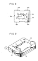
- a play card 52 which is a flexible sheet having a predetermined character 53 printed on one or both surfaces thereof as shown in Figure 8, can be loaded on the picture-making area 10b of the tablet 10 of the graphic computer 1.
- the play card 52 is substantially rectangular, and has two protruding portions (inserting portions) 52b, 52c formed on an upper side portion thereof, two protruding portions (inserting portions) 52d, 52e formed on a lower side portion thereof, and a semicircular notch 52a for ejecting the play card formed on a left side portion thereof.
- the inserting portions 52b and 52c of the upper side portion of the play card 52 are respectively inserted into the slots 4b and 4c adjacent to the tablet 10 on the upper casing 4 of the graphic computer 1, while the play card 52 is slightly deformed as shown in Figure 9. Then, the inserting portions 52d and 52e of the lower side portion of the play card 52 are respectively inserted into the slots 4d and 4e of the upper casing 4 (see Figure 1), whereby the play card 52 is stably loaded on the tablet 10 as shown in Figure 10.
- the play card 52 can be used in a variety of ways, for example for tracing or playing a puzzle game or the like. If the user selects tracing, respective portions of the character 53 of the play card 52 shown in Figure 8 are marked with, for example, numerals such as 1′, 2′, 3′,.... . In one case, the user will trace the respective portions of the character 53 in the order 1′, 3′, 5′, 8′, .... . In any other case, the user will trace the respective portions of the character 53 in the order 1′, 2′, 4′, 7′, ... so that, for example, respective different animal characters are displayed on the picture screen 2a of the monitor 2 in accordance with the order of tracing. In other words, a kind of hidden picture search play becomes possible.
- words having ciphers are printed in advance on the play card 52 and the user writes words while guessing the ciphers.
- the play card 52 is used, the system in the example of Figure 1 can be applied, not only to picture drawing but also to sophisticated play or to a kind of learning. Since the play card 52 is provided with the inserting portions 52b to 52e while the slots 4b to 4e are formed on the portion in which the upper case 4 of the graphic computer 1 contacts the tablet 10, the play card 52 can be loaded on the graphic computer with ease. Moreover, since the play card 52 is provided with the notch 52a for ejecting the play card, the play card can be ejected from the graphic computer 1 with ease.
- a leaf spring may be provided on an edge portion of the recess 4a of the upper casing in in order to fix a peripheral section of the play card 52. In that case, the play card need not be provided with the inserting portions 52b to 52e.
- the counter 48 keeps counting the clock pulses from the CPU 38.
- the CPU 38 causes the counter 48 to clear the count value.
- the CPU 38 holds the condition of the counter 48 in which the count value of the counter 48 is cleared.
- the count value of the counter 48 reaches the value equivalent to five minutes so that the counter 48 supplies the alarm signal AL to the CPU 38.
- the CPU 38 Upon receiving the alarm signal AL, the CPU 38 causes the alarm circuit 49 to perform the alarm operation through the I/O interface circuit 41, whereby an alarm sound, such as predetermined sound, melody, message etc., emanates from the speaker 50 for two minutes. Thus, the user is warned that he has inadvertently left the power switch 6 in its ON state. If the power switch 6 is not turned OFF during the time period of two minutes during which the speaker 50 emanates sound, the CPU 38 holds the condition of the counter 48 in which the count value of the counter 48 is cleared.
- an alarm sound such as predetermined sound, melody, message etc.
- the graphic computer 1 of this embodiment has programmed therein a demonstration mode (shop display mode) in addition to the above-described normal mode.
- the demonstration mode is utilised to display the apparatus shown in Figure 1 so that a customer can freely operate the apparatus in a shop window of the shop.
- the slidable contact is moved to turn ON the power switch 6 while the clear button 7 is depressed.
- the demonstration display begins after the graphic computer 1 is powered up.
- the displayed picture is cleared and the graphic computer is set in the picture drawing mode, in which mode the user can draw a picture freely, similarly to the normal mode.
- a program controlling the demonstration mode is so designed that, in the demonstration mode, if the user does not operate the graphic computer 1 for five minutes (until the demonstration display is ended) after the power switch is turned ON, or if the user does not operate the graphic computer for 5 minutes during the picture drawing mode after the demonstration display is ended, the picture displayed on the picture screen 2a of the monitor 2 is cleared completely and the demonstration display is started once again. More specifically, the CPU 38, supplied with the alarm signal AL from the counter 48 when the demonstration mode is set, executes the demonstration display program once again without operating the alarm circuit 48. If the user operates the graphic computer 1 during the demonstration display mode, the picture displayed on the picture screen 2a is cleared and the graphic computer is set in the drawing mode.
- the graphic computer 1 may incorporate therein a colour or monochromatic printer (dot printer, printer-plotter, etc.) as shown in Figure 11, so that the user can print a desired picture 54 at any time.
- a colour or monochromatic printer dot printer, printer-plotter, etc.
- an integrated circuit (IC) card in which application software is written, or a voice IC card acting as a pulse signal generator or an FM sound source, etc. may be provided in the form of an attachable/detachable card 55.
- the graphic computer 1 may incorporate therein a disc driving apparatus for a 2 inch or 3.5 inch floppy disc.
- the monitor 2 may be replaced with a liquid crystal display (LCD) 56 as shown in Figure 12.
- LCD liquid crystal display
- the LCD 56 may be mounted on the cabinet of the graphic computer 1 so as to be freely rotatable. If the graphic computer 1 and the LCD 56 are formed unitarily in this way, the overall arrangement can be more simplified, and the graphic computer can be used more conveniently because the coordinate input section and the image display section are located close to each other. (The LCD 56 may be replaced with an electroluminescent (EL) panel.)
- EL electroluminescent
- the composite video signal CV of the graphic computer 1 is supplied to the monitor 2 or the like
- the composite video signal CV may instead or also be directly supplied to a video tape recorder or to an electronic camera, whereby the signal may be recorded on a video tape, a floppy disc or the like.
- the apparatus may be so designed that a predetermined melody and/or message are emanated from the speaker 50 while the demonstration picture is displayed on the picture screen of the television monitor.
- the constituent parts of the apparatus are accommodated in the same cabinet and made unitary so that the overall arrangement of the apparatus can be miniaturised.
- the apparatus can be made ready for use merely by connecting the video signal forming circuit (the computer) to the output device (the monitor 2) via for example, the video cable 3.
- the video signal forming circuit the computer
- the output device the monitor 2
- the mechanical construction of the computer 1 can be simplified and the functions thereof can be extended.
- the display device (56) is attached to the cabinet as the output device, then the overall arrangement of the apparatus can be simplified more. Also, the coordinate detecting portion and the video image display portion are provided close to each other so that the portable graphic computer apparatus can be made easier to handle.
- the alarm sound emanates from the speaker 50 so that the user can be warned against inadvertently leaving the power switch 6 in its ON state.
- the portable graphic computer apparatus is suitable for exhibition at a shop front or the like for demonstration purposes.
- the overall arrangement of the above-described portable graphic computer apparatus can be made compact in size and it can be utilised by children with ease. Further, since the tracing sheet or paper (if provided) is fixedly mounted on the tablet 10 and the tracing sheet can be utilised as a kind of teaching material, the advantage arises that the portable graphic computer apparatus can be made more useful.
Landscapes
- Engineering & Computer Science (AREA)
- Multimedia (AREA)
- Human Computer Interaction (AREA)
- General Engineering & Computer Science (AREA)
- Theoretical Computer Science (AREA)
- Physics & Mathematics (AREA)
- General Physics & Mathematics (AREA)
- Toys (AREA)
- Processing Or Creating Images (AREA)
- User Interface Of Digital Computer (AREA)
- Position Input By Displaying (AREA)
Priority Applications (2)
| Application Number | Priority Date | Filing Date | Title |
|---|---|---|---|
| EP95201071A EP0667566B1 (de) | 1989-08-25 | 1990-08-24 | Tragbarer graphischer Rechner |
| EP95201070A EP0667568B1 (de) | 1989-08-25 | 1990-08-24 | Tragbarer graphischer Rechner |
Applications Claiming Priority (6)
| Application Number | Priority Date | Filing Date | Title |
|---|---|---|---|
| JP219813/89 | 1989-08-25 | ||
| JP21981489A JP3082200B2 (ja) | 1989-08-25 | 1989-08-25 | 画像作成装置 |
| JP219814/89 | 1989-08-25 | ||
| JP219812/89 | 1989-08-25 | ||
| JP21981289 | 1989-08-25 | ||
| JP1219813A JPH0383116A (ja) | 1989-08-25 | 1989-08-25 | 画像作成装置 |
Related Child Applications (4)
| Application Number | Title | Priority Date | Filing Date |
|---|---|---|---|
| EP95201071A Division EP0667566B1 (de) | 1989-08-25 | 1990-08-24 | Tragbarer graphischer Rechner |
| EP95201070.0 Division-Into | 1990-08-24 | ||
| EP95201070A Division EP0667568B1 (de) | 1989-08-25 | 1990-08-24 | Tragbarer graphischer Rechner |
| EP95201071.8 Division-Into | 1990-08-24 |
Publications (3)
| Publication Number | Publication Date |
|---|---|
| EP0414565A2 true EP0414565A2 (de) | 1991-02-27 |
| EP0414565A3 EP0414565A3 (en) | 1993-03-10 |
| EP0414565B1 EP0414565B1 (de) | 1999-04-28 |
Family
ID=27330359
Family Applications (3)
| Application Number | Title | Priority Date | Filing Date |
|---|---|---|---|
| EP90309327A Expired - Lifetime EP0414565B1 (de) | 1989-08-25 | 1990-08-24 | Tragbarer graphischer Rechner |
| EP95201071A Expired - Lifetime EP0667566B1 (de) | 1989-08-25 | 1990-08-24 | Tragbarer graphischer Rechner |
| EP95201070A Expired - Lifetime EP0667568B1 (de) | 1989-08-25 | 1990-08-24 | Tragbarer graphischer Rechner |
Family Applications After (2)
| Application Number | Title | Priority Date | Filing Date |
|---|---|---|---|
| EP95201071A Expired - Lifetime EP0667566B1 (de) | 1989-08-25 | 1990-08-24 | Tragbarer graphischer Rechner |
| EP95201070A Expired - Lifetime EP0667568B1 (de) | 1989-08-25 | 1990-08-24 | Tragbarer graphischer Rechner |
Country Status (6)
| Country | Link |
|---|---|
| US (1) | US6191777B1 (de) |
| EP (3) | EP0414565B1 (de) |
| AU (1) | AU622823B2 (de) |
| BR (1) | BR9004179A (de) |
| DE (3) | DE69033661T2 (de) |
| ES (3) | ES2130117T3 (de) |
Cited By (6)
| Publication number | Priority date | Publication date | Assignee | Title |
|---|---|---|---|---|
| EP0476809A3 (en) * | 1990-08-31 | 1993-02-10 | Sony Corporation | Graphic image processing apparatus |
| US5311207A (en) * | 1990-04-19 | 1994-05-10 | Sony Corporation | Image drawing apparatus for displaying input image on display means |
| EP0663658A1 (de) * | 1994-01-14 | 1995-07-19 | Binney & Smith Inc. | Elektronische Zeichenvorrichtung |
| EP0677824A3 (de) * | 1989-04-17 | 1996-02-28 | Quantel Ltd | Elektronisches graphisches System. |
| EP2034392A4 (de) * | 2006-06-22 | 2009-11-11 | Konami Digital Entertainment | Linienform-verarbeitungseinrichtung, linienform-verarbeitungsverfahren, informationsaufzeichnungsmedium und programm |
| CN104980784A (zh) * | 2014-04-14 | 2015-10-14 | Lg电子株式会社 | 多媒体装置及其光标控制方法 |
Families Citing this family (35)
| Publication number | Priority date | Publication date | Assignee | Title |
|---|---|---|---|---|
| JPH09114591A (ja) | 1995-10-12 | 1997-05-02 | Semiconductor Energy Lab Co Ltd | 液晶表示装置及びその表示方法 |
| JPH10166666A (ja) * | 1996-12-06 | 1998-06-23 | King Jim Co Ltd | 文字情報処理装置 |
| JP3792920B2 (ja) * | 1998-12-25 | 2006-07-05 | 株式会社東海理化電機製作所 | タッチ操作入力装置 |
| US7410471B1 (en) | 1998-09-18 | 2008-08-12 | Becker Orthopedic Appliance Company | Orthosis knee joint and sensor |
| US6517503B1 (en) | 1998-09-18 | 2003-02-11 | Becker Orthopedic Appliance Company | Orthosis knee joint |
| US6578022B1 (en) * | 2000-04-18 | 2003-06-10 | Icplanet Corporation | Interactive intelligent searching with executable suggestions |
| US6618040B1 (en) * | 2000-09-15 | 2003-09-09 | Targus Communications Corp. | Apparatus and method for indexing into an electronic document to locate a page or a graphical image |
| US6980333B2 (en) * | 2001-04-11 | 2005-12-27 | Eastman Kodak Company | Personalized motion imaging system |
| US6538643B2 (en) * | 2001-04-25 | 2003-03-25 | Interlink Electronics, Inc. | Remote control having a touch pad operable in a pad-to-screen mapping mode for highlighting preselected parts of a slide displayed on a display screen |
| JP4057253B2 (ja) * | 2001-05-29 | 2008-03-05 | アルプス電気株式会社 | 入力装置及び電子機器 |
| USD491565S1 (en) | 2001-10-16 | 2004-06-15 | Mattel, Inc. | Cartridge for a hand-held electronic toy |
| USD479716S1 (en) | 2001-10-16 | 2003-09-16 | Mattel, Inc. | Hand-held electronic drawing device |
| US20040041933A1 (en) * | 2002-08-29 | 2004-03-04 | Eastman Kodak Company | Demo via on-camera display with power jack |
| WO2004075004A2 (en) * | 2003-02-14 | 2004-09-02 | Mattel, Inc. | Hand-held interactive electronic device |
| AU2003291912A1 (en) * | 2003-12-19 | 2005-07-05 | Intel China Ltd. | Creating responses for an electronic pen-computer multimedia interactive system |
| JP4127536B2 (ja) * | 2004-01-20 | 2008-07-30 | 任天堂株式会社 | ゲーム装置及びゲームプログラム |
| JP4141389B2 (ja) * | 2004-01-20 | 2008-08-27 | 任天堂株式会社 | ゲーム装置及びゲームプログラム |
| JP4388878B2 (ja) | 2004-10-19 | 2009-12-24 | 任天堂株式会社 | 入力処理プログラムおよび入力処理装置 |
| US20060166592A1 (en) * | 2005-01-26 | 2006-07-27 | Nielsen Paul S | Electronic drawing toy |
| JP4262217B2 (ja) * | 2005-04-26 | 2009-05-13 | 任天堂株式会社 | ゲームプログラム及びゲーム装置 |
| JP4260770B2 (ja) * | 2005-05-09 | 2009-04-30 | 任天堂株式会社 | ゲームプログラムおよびゲーム装置 |
| JP4312737B2 (ja) * | 2005-05-13 | 2009-08-12 | 任天堂株式会社 | ゲームプログラムおよびゲーム装置 |
| JP4603931B2 (ja) * | 2005-05-16 | 2010-12-22 | 任天堂株式会社 | オブジェクト移動制御装置およびオブジェクト移動制御プログラム |
| US7887058B2 (en) * | 2005-07-07 | 2011-02-15 | Mattel, Inc. | Methods of playing drawing games and electronic game systems adapted to interactively provide the same |
| US8537273B2 (en) * | 2005-10-27 | 2013-09-17 | Hewlett-Packard Development Company, L.P. | Demo dock for digital cameras |
| US8574050B2 (en) | 2005-11-04 | 2013-11-05 | Mattel, Inc. | Game unit with dual joystick controllers |
| US7874918B2 (en) | 2005-11-04 | 2011-01-25 | Mattel Inc. | Game unit with motion and orientation sensing controller |
| US8568213B2 (en) | 2005-11-04 | 2013-10-29 | Mattel, Inc. | Game unit with controller-determined characters |
| US8187051B2 (en) * | 2007-10-26 | 2012-05-29 | Mattel, Inc. | Digital arts and crafts computer peripheral toy device |
| US20090174656A1 (en) * | 2008-01-07 | 2009-07-09 | Rudell Design Llc | Electronic image identification and animation system |
| US8752141B2 (en) * | 2008-06-27 | 2014-06-10 | John Nicholas | Methods for presenting and determining the efficacy of progressive pictorial and motion-based CAPTCHAs |
| HU3838U (en) * | 2010-06-07 | 2010-10-28 | Ambrus Sandor Dr | Anti-theft show-room apparatus |
| CN102902351A (zh) * | 2011-07-25 | 2013-01-30 | 富泰华工业(深圳)有限公司 | 触摸式电子装置 |
| CN103376981A (zh) * | 2012-04-19 | 2013-10-30 | 富泰华工业(深圳)有限公司 | 绘图系统及方法、以及具有该绘图系统的触控式电子装置 |
| CN115131953A (zh) * | 2022-07-01 | 2022-09-30 | 应急管理部上海消防研究所 | 手动报警器体验装置以及体验方法 |
Family Cites Families (14)
| Publication number | Priority date | Publication date | Assignee | Title |
|---|---|---|---|---|
| US3778910A (en) * | 1972-06-22 | 1973-12-18 | L Smalligan | Writing aid |
| JPS5890235A (ja) | 1981-11-22 | 1983-05-28 | Sony Corp | 位置検出装置 |
| JPS58149578A (ja) * | 1982-02-27 | 1983-09-05 | Fanuc Ltd | 情報入力領域設定方式 |
| US4467322A (en) * | 1982-08-30 | 1984-08-21 | Sperry Corporation | Digital shade control for color CRT background and cursors |
| GB2141907A (en) * | 1983-06-02 | 1985-01-03 | Michael Gilmore | Video games with advertising facility |
| US4633436A (en) * | 1983-12-16 | 1986-12-30 | International Business Machines Corp. | Real-time rub-out erase for an electronic handwriting facility |
| US4709230A (en) * | 1985-04-19 | 1987-11-24 | Questron, Inc. | Color converter |
| US4604062A (en) * | 1985-07-29 | 1986-08-05 | Woods Margaret H | Drawing/tracing/template apparatus |
| US4764763A (en) | 1985-12-13 | 1988-08-16 | The Ohio Art Company | Electronic sketching device |
| JPS6380356A (ja) * | 1986-09-24 | 1988-04-11 | Seiko Instr & Electronics Ltd | 電子リマインダ |
| US4782335B1 (en) * | 1986-10-30 | 1993-09-21 | L. Gussin Edward | Video art electronic system |
| DE3804640A1 (de) * | 1988-02-15 | 1989-09-07 | Baumann Heinz W Dipl Ing Fh | Digitalisier-anzeige-tablett |
| US4912466A (en) * | 1988-09-15 | 1990-03-27 | Npd Research Inc. | Audio frequency based data capture tablet |
| JP2784811B2 (ja) * | 1989-08-25 | 1998-08-06 | ソニー株式会社 | 画像作成装置 |
-
1990
- 1990-08-09 AU AU60825/90A patent/AU622823B2/en not_active Ceased
- 1990-08-23 BR BR909004179A patent/BR9004179A/pt not_active IP Right Cessation
- 1990-08-24 EP EP90309327A patent/EP0414565B1/de not_active Expired - Lifetime
- 1990-08-24 DE DE69033661T patent/DE69033661T2/de not_active Expired - Fee Related
- 1990-08-24 ES ES90309327T patent/ES2130117T3/es not_active Expired - Lifetime
- 1990-08-24 DE DE69033075T patent/DE69033075T2/de not_active Expired - Fee Related
- 1990-08-24 EP EP95201071A patent/EP0667566B1/de not_active Expired - Lifetime
- 1990-08-24 DE DE69033097T patent/DE69033097T2/de not_active Expired - Fee Related
- 1990-08-24 EP EP95201070A patent/EP0667568B1/de not_active Expired - Lifetime
- 1990-08-24 ES ES95201070T patent/ES2130514T3/es not_active Expired - Lifetime
- 1990-08-24 ES ES95201071T patent/ES2151020T3/es not_active Expired - Lifetime
-
1994
- 1994-04-29 US US08/236,660 patent/US6191777B1/en not_active Expired - Fee Related
Cited By (12)
| Publication number | Priority date | Publication date | Assignee | Title |
|---|---|---|---|---|
| EP0677824A3 (de) * | 1989-04-17 | 1996-02-28 | Quantel Ltd | Elektronisches graphisches System. |
| EP0677825A3 (de) * | 1989-04-17 | 1996-06-12 | Quantel Ltd | Elektronisches graphisches System. |
| US5311207A (en) * | 1990-04-19 | 1994-05-10 | Sony Corporation | Image drawing apparatus for displaying input image on display means |
| EP0476809A3 (en) * | 1990-08-31 | 1993-02-10 | Sony Corporation | Graphic image processing apparatus |
| EP0663658A1 (de) * | 1994-01-14 | 1995-07-19 | Binney & Smith Inc. | Elektronische Zeichenvorrichtung |
| US5604517A (en) * | 1994-01-14 | 1997-02-18 | Binney & Smith Inc. | Electronic drawing device |
| EP2034392A4 (de) * | 2006-06-22 | 2009-11-11 | Konami Digital Entertainment | Linienform-verarbeitungseinrichtung, linienform-verarbeitungsverfahren, informationsaufzeichnungsmedium und programm |
| US8244073B2 (en) | 2006-06-22 | 2012-08-14 | Konami Digital Entertainment Co. Ltd. | Line shape processing device, line shape processing method, information recording medium, and program |
| CN104980784A (zh) * | 2014-04-14 | 2015-10-14 | Lg电子株式会社 | 多媒体装置及其光标控制方法 |
| EP2934002A1 (de) * | 2014-04-14 | 2015-10-21 | LG Electronics Inc. | Multimediavorrichtung und Verfahren zur Steuerung eines Mauszeigers dafür |
| US9606638B2 (en) | 2014-04-14 | 2017-03-28 | Lg Electronics Inc. | Multimedia device and method of controlling a cursor thereof |
| CN104980784B (zh) * | 2014-04-14 | 2018-07-20 | Lg电子株式会社 | 多媒体装置及其光标控制方法 |
Also Published As
| Publication number | Publication date |
|---|---|
| AU622823B2 (en) | 1992-04-16 |
| EP0667566A1 (de) | 1995-08-16 |
| EP0667568B1 (de) | 1999-05-06 |
| EP0414565A3 (en) | 1993-03-10 |
| DE69033661T2 (de) | 2001-05-03 |
| ES2130117T3 (es) | 1999-07-01 |
| ES2151020T3 (es) | 2000-12-16 |
| DE69033075D1 (de) | 1999-06-02 |
| EP0667568A1 (de) | 1995-08-16 |
| EP0414565B1 (de) | 1999-04-28 |
| BR9004179A (pt) | 1991-09-03 |
| DE69033097T2 (de) | 1999-11-11 |
| DE69033097D1 (de) | 1999-06-10 |
| DE69033075T2 (de) | 1999-10-28 |
| EP0667566B1 (de) | 2000-11-08 |
| US6191777B1 (en) | 2001-02-20 |
| DE69033661D1 (de) | 2000-12-14 |
| AU6082590A (en) | 1991-03-14 |
| ES2130514T3 (es) | 1999-07-01 |
Similar Documents
| Publication | Publication Date | Title |
|---|---|---|
| EP0667566B1 (de) | Tragbarer graphischer Rechner | |
| EP0414566B1 (de) | Tragbarer graphischer Rechner | |
| US5511983A (en) | Graphic image generating apparatus with automatic demonstration image generating program | |
| US6572378B1 (en) | Electronic drawing assist toy | |
| CA2023962C (en) | Portable graphic computer apparatus | |
| JP2797642B2 (ja) | 座標入力装置及び座標情報入力補助部材 | |
| JP3185714B2 (ja) | 画像作成装置及び画像作成方法 | |
| JP3082200B2 (ja) | 画像作成装置 | |
| KR930005805B1 (ko) | 화상 작성장치 및 덧그리기용의 시트 | |
| JPH04326112A (ja) | 画像作成装置の入力装置 | |
| JPH04328623A (ja) | 画像作成装置の入力装置 | |
| JPH04111627U (ja) | 座標情報入力補助部材 | |
| JPH0341077B2 (de) | ||
| JP2000043488A (ja) | 筆記軌跡出力装置および記憶媒体 | |
| JPH05342319A (ja) | 画像作成装置 | |
| JP2008171440A (ja) | 装置 | |
| JP2008097629A (ja) | 装置 |
Legal Events
| Date | Code | Title | Description |
|---|---|---|---|
| PUAI | Public reference made under article 153(3) epc to a published international application that has entered the european phase |
Free format text: ORIGINAL CODE: 0009012 |
|
| AK | Designated contracting states |
Kind code of ref document: A2 Designated state(s): DE ES FR GB NL |
|
| PUAL | Search report despatched |
Free format text: ORIGINAL CODE: 0009013 |
|
| AK | Designated contracting states |
Kind code of ref document: A3 Designated state(s): DE ES FR GB NL |
|
| 17P | Request for examination filed |
Effective date: 19930809 |
|
| 17Q | First examination report despatched |
Effective date: 19950113 |
|
| GRAG | Despatch of communication of intention to grant |
Free format text: ORIGINAL CODE: EPIDOS AGRA |
|
| GRAG | Despatch of communication of intention to grant |
Free format text: ORIGINAL CODE: EPIDOS AGRA |
|
| GRAH | Despatch of communication of intention to grant a patent |
Free format text: ORIGINAL CODE: EPIDOS IGRA |
|
| GRAH | Despatch of communication of intention to grant a patent |
Free format text: ORIGINAL CODE: EPIDOS IGRA |
|
| GRAA | (expected) grant |
Free format text: ORIGINAL CODE: 0009210 |
|
| AK | Designated contracting states |
Kind code of ref document: B1 Designated state(s): DE ES FR GB NL |
|
| XX | Miscellaneous (additional remarks) |
Free format text: TEILANMELDUNG 95201070.0 EINGEREICHT AM 24/08/90. |
|
| REF | Corresponds to: |
Ref document number: 69033075 Country of ref document: DE Date of ref document: 19990602 |
|
| REG | Reference to a national code |
Ref country code: ES Ref legal event code: FG2A Ref document number: 2130117 Country of ref document: ES Kind code of ref document: T3 |
|
| ET | Fr: translation filed | ||
| PLBE | No opposition filed within time limit |
Free format text: ORIGINAL CODE: 0009261 |
|
| STAA | Information on the status of an ep patent application or granted ep patent |
Free format text: STATUS: NO OPPOSITION FILED WITHIN TIME LIMIT |
|
| 26N | No opposition filed | ||
| PGFP | Annual fee paid to national office [announced via postgrant information from national office to epo] |
Ref country code: FR Payment date: 20010810 Year of fee payment: 12 |
|
| PGFP | Annual fee paid to national office [announced via postgrant information from national office to epo] |
Ref country code: DE Payment date: 20010820 Year of fee payment: 12 |
|
| PGFP | Annual fee paid to national office [announced via postgrant information from national office to epo] |
Ref country code: GB Payment date: 20010822 Year of fee payment: 12 |
|
| PGFP | Annual fee paid to national office [announced via postgrant information from national office to epo] |
Ref country code: ES Payment date: 20010824 Year of fee payment: 12 |
|
| PGFP | Annual fee paid to national office [announced via postgrant information from national office to epo] |
Ref country code: NL Payment date: 20010830 Year of fee payment: 12 |
|
| REG | Reference to a national code |
Ref country code: GB Ref legal event code: IF02 |
|
| PG25 | Lapsed in a contracting state [announced via postgrant information from national office to epo] |
Ref country code: GB Free format text: LAPSE BECAUSE OF NON-PAYMENT OF DUE FEES Effective date: 20020824 |
|
| PG25 | Lapsed in a contracting state [announced via postgrant information from national office to epo] |
Ref country code: ES Free format text: LAPSE BECAUSE OF NON-PAYMENT OF DUE FEES Effective date: 20020825 |
|
| PG25 | Lapsed in a contracting state [announced via postgrant information from national office to epo] |
Ref country code: NL Free format text: LAPSE BECAUSE OF NON-PAYMENT OF DUE FEES Effective date: 20030301 Ref country code: DE Free format text: LAPSE BECAUSE OF NON-PAYMENT OF DUE FEES Effective date: 20030301 |
|
| GBPC | Gb: european patent ceased through non-payment of renewal fee |
Effective date: 20020824 |
|
| PG25 | Lapsed in a contracting state [announced via postgrant information from national office to epo] |
Ref country code: FR Free format text: LAPSE BECAUSE OF NON-PAYMENT OF DUE FEES Effective date: 20030430 |
|
| NLV4 | Nl: lapsed or anulled due to non-payment of the annual fee |
Effective date: 20030301 |
|
| REG | Reference to a national code |
Ref country code: FR Ref legal event code: ST |
|
| REG | Reference to a national code |
Ref country code: ES Ref legal event code: FD2A Effective date: 20030912 |