EP0414643A2 - Méthode et appareil pour la commande et la surveillance d'appareil robot à moteur linéaire - Google Patents
Méthode et appareil pour la commande et la surveillance d'appareil robot à moteur linéaire Download PDFInfo
- Publication number
- EP0414643A2 EP0414643A2 EP90810620A EP90810620A EP0414643A2 EP 0414643 A2 EP0414643 A2 EP 0414643A2 EP 90810620 A EP90810620 A EP 90810620A EP 90810620 A EP90810620 A EP 90810620A EP 0414643 A2 EP0414643 A2 EP 0414643A2
- Authority
- EP
- European Patent Office
- Prior art keywords
- signal
- break
- robot
- loose
- acceleration
- Prior art date
- Legal status (The legal status is an assumption and is not a legal conclusion. Google has not performed a legal analysis and makes no representation as to the accuracy of the status listed.)
- Granted
Links
Images


Classifications
-
- G—PHYSICS
- G05—CONTROLLING; REGULATING
- G05B—CONTROL OR REGULATING SYSTEMS IN GENERAL; FUNCTIONAL ELEMENTS OF SUCH SYSTEMS; MONITORING OR TESTING ARRANGEMENTS FOR SUCH SYSTEMS OR ELEMENTS
- G05B19/00—Program-control systems
- G05B19/02—Program-control systems electric
- G05B19/18—Numerical control [NC], i.e. automatically operating machines, in particular machine tools, e.g. in a manufacturing environment, so as to execute positioning, movement or co-ordinated operations by means of program data in numerical form
- G05B19/406—Numerical control [NC], i.e. automatically operating machines, in particular machine tools, e.g. in a manufacturing environment, so as to execute positioning, movement or co-ordinated operations by means of program data in numerical form characterised by monitoring or safety
- G05B19/4062—Monitoring servoloop, e.g. overload of servomotor, loss of feedback or reference
Definitions
- the present invention relates to robot systems and the like, and more particularly, to a novel preprogrammable monitoring technique for preventing robots driven by linear motors as well as the other components of the robot system, from being damaged due to stalling.
- Linear motors are extremely advantageous for use as a means for moving or driving a device, such as, for example, a robot.
- a linear stepping motor (much like a rotary stepping motor) is caused to move by advancing magnetic fields developed within the linear stepping motor forcer in order to develop relative motion with respect to its stator which, in the example given, is maintained stationary.
- a linear stepping motor is a synchronous machine since its advancing fields must very closely track its actual motion. If the fields lose synchronism with the actual motion, the motor stalls and develops no torque or force.
- the position control of the linear motor is open-loop.
- the position control of an xy motor is also open-loop in the absence of position feedback or other position tracking devices.
- Stall i.e. the loss of motor force due to the loss of electromagnetic synchronization with the etched pattern of the platen. This condition or stall can occur during:
- a stall can cause the device driving by the linear motor to slide along the platen in an uncontrolled fashion where subsequent collisions can occur with other objects in the workpiece, other devices driven by their linear motors along the platen, or with the edge boundaries of the platen.
- a stall also allows the possibility of the device driven by the linear motor realigning itself with the platen grid at a totally unknown position or in an unknown orientation where the direction of motion is now unknown. If the device driven by the linear motor is realigned in an unknown orientation, the next commanded move given to such device causes a collision or stall to occur.
- a stall causes the xy linear motor position on the platen to be unknown, thereby rendering the control apparatus useless in determining and protecting against collisions.
- the linear motors described hereinabove have been used to great advantage in multi-robot systems, such as, for example, the system described in copending Application Serial No. , filed and assigned to the assignee of the present invention (Megamation 3.0-003), which application is incorporated herein by reference thereto.
- the robot system of copending Application Serial No. is comprised of a plurality of robot devices, each having a two-dimensional (i.e. xy) linear motor, typically referred to as an xy forcer capable of generating electromagnetic fields in mutually perpendicular directions, which fields develop eddy currents in a platen cooperating with the xy forcers.
- the platen is mounted in a stationary fashion so that the relative motion between the platen and the multiple robots cause the robots to move across the platen.
- the motion control system employed to move the robot in the x and y directions consists of a main controller and motor drive electronics.
- the main controller outputs are comprised of motor step pulses and motor direction signals for each of the x and y forcers.
- the motor drive electronics converts the step pulses and motor direction signals into analog voltages required to drive the power amplifiers, which in turn drive the coil windings of the linear xy motor.
- Suitable xy linear motors for this purpose are produced by Xynetics of Santa Clara, California.
- a stall can cause the moving robot arm to slide along the platen in an uncontrolled fashion wherein subsequent collisions can occur with other objects in the workspace, other robot arms on the platen or with the edge boundaries of the platen.
- a stall can also allow the possibility of the robot arm realigning itself with the platen grid at a totally unknown position or in an unknown orientation where the direction of motion is now unknown. If realigned in an unknown orientation, the next commanded move given to a robot arm can cause a collision or a stall to occur.
- a stall causes the xy motor position on the platen to be unknown thereby rendering useless the system control software, for example, the anti-collision software described in copending Application Serial No. (Megamation 3.0-006), filed and assigned to the assignee of the present application.
- the present invention is characterized by comprising a damping control servo system forming part of the motor drive electronics to provide increased xy performance.
- the damping servo system is implemented using feedback from a set of accelerometers located in the robot arm adjacent to the xy linear motor. By monitoring the expected (or demanded) acceleration requested by the motor controller and the actual acceleration measured by the accelerometers in the xy linear motor, the motor drive electronics can correct for acceleration errors of the two-dimensional linear motor as it moves from point to point.
- the robot or other moving device, is provided with an accelerometer for generating a signal representing the magnitude and direction of acceleration.
- the actual acceleration (magnitude and direction) is compared against the commanded signal to provide a difference signal.
- the difference signal is amplified and compared against safe limits which may be preprogrammed to take into account the dynamics of the system specifications presently abiding. In the event that the difference signals falls outside of the preprogrammed safe limits, a "break-loose" signal is generated. This break-loose signal is monitored for its duration which may be anywhere from one to several hundred milliseconds.
- the duration of the break-loose signal is monitored by a pulse width discriminator which can be preprogrammed to allow minimum pulse widths of from one to a maximum of 255 milliseconds, for example, before generating a break-loose interrupt condition.
- the discriminator Assuming that the break-loose signal persists for the minimum preset period, the discriminator generates a signal which sets a latch.
- the latch generates a system emergency signal and remains in the set state until examined by the system computer.
- the system emergency signal immediately shuts off the xy linear motor air bearings and all AC power to the moving systems to prevent the linear motor driven robots from being damaged as well as from damaging other robots and objects located in the workspace.
- the latch remains in the set state until reset by the computer, which examines the latches of all of the break-loose circuits to determine the precise source of the break-loose condition.
- a monitoring device is provided for each robot arm employed in the multi-robot system.
- Still another object of the present invention is to provide method and apparatus for preventing systems having stalled linear motors from being damaged or from damaging other moving or stationary objects within the system due to a stalled condition.
- Still another object of the present invention is to provide a novel method and apparatus for monitoring linear motors to detect the occurrence of a stalled condition comprising means for adjustably setting the limits for determining a stall wherein said limits may include at least one of the differences between a commanded acceleration signal and the actual acceleration signal of a linear motor and the duration of the difference signal falling outside of the safe limits.
- Still another object of the present invention is to provide a novel method for determining a stalled condition including the steps of measuring the actual acceleration of a device driven by a linear motor; determining the difference between the actual acceleration and the commanded acceleration; determining whether said difference signal lies outside a predetermined safe range; determining the duration of a difference signal lying outside of the safe limits and generating a system emergency signal in the event that an unsafe difference signal persists for a predetermined time, said predetermined time being adjustably set according to system parameters for the particular job.
- Still another object of the present invention is to provide a novel method for immediately decoupling motive power from linear motors when a predetermined acceleration condition exists for a predetermined time interval to protect the system components from damage.
- Fig. 1 shows a multiple robot system 10 embodying the principles of the present invention and comprised of a housing 12 mounted upon supports 14 and containing the control cabinet for the system electronics.
- An array of operating buttons 16 and touchscreen 18, also employed for control purposes as well as for display, are arranged along the exterior of the control cabinet 12.
- System 10 is of the overhead system type in which a conveyor (not shown) or other form of worksurface extends through or may be moved through the open region defined by the supports 14 in order to align workpieces on a worksurface arranged beneath the robots 20, 20′. Only two robot arms are shown for purposes of simplicity, it being understood that a greater or even lesser number may be used and operated simultaneously in system 10.
- the robots are connected to the control circuitry by an umbilical cord 20a, 20a′.
- the robots are powered by electromagnets contained within the robot housing and are attracted to an upper plate 22, referred to as a platen, by permanent magnets.
- the robots slide along platen 22 on a layer of compressed air.
- the robots each include xy forcers, i.e. two-dimensional linear motors, capable of moving the robot in mutually perpendicular directions along the overhead platen 22 by motor drive pulses commanded by the system controller and may be of the type described in copending Application Serial No. 112,534, filed October 26, 1987 and assigned to the assignee of the present application, said application being incorporated herein by reference thereto.
- the motor control system employed to move each robot 20, 20′ in the directions of the x and y axes is comprised of a main controller and motor drive electronics.
- the main controller outputs are motor step pulses and motor direction signals for each linear motor respectively driving the robot arm in the x and y direction.
- the motor drive electronics converts the step pulses and motor direction signals into analog voltages required to drive the power amplifiers which, in turn, drive the coil windings of the 2-axis linear xy motor.
- These devices are conventional and may be obtained, for example, from Xynetics of Santa Clara, California.
- the linear stepping motors are synchronous machines in which the advancing fields must very closely track actual motion. If the fields lose synchronism with the actual motion, the motor stalls and develops no torque or force.
- the position control of the xy motor is open-loop.
- the absence of direction position feedback allows the possibility of errors due to the loss of motor force due to a loss of electromagnetic synchronization with the etched pattern of the platen, typically referred to as a stall, which condition can occur as a result of either the failure of the mass of the robot arm to keep up with advancing electromagnetic waves during acceleration, the failure of a robot arm to be stopped by the electromagnetic wave due to the inability of the electromagnetic wave to overcome the inertia of the robot arm and a collision which may be caused when a robot arm strikes an object in the workplace.
- a stall can cause an arm to slide along the platen in an uncontrolled fashion enabling the potentiality for subsequent collisions with other objects in the workspace, other arms on the platen or with the edge boundaries of the platen.
- a stall also permits the possibility of the arm realigning itself with the platen grid at a totally unknown position or in an unknown orientation wherein the direction of motion is now unknown. If realigned in an unknown orientation, the next commanded move given to the arm may result in a collision or stall.
- a stall causes the xy motor position on the platen to be unknown thereby rendering anti-collision techniques useless.
- the present invention in order to provide increased xy performance, utilizes a damping control servo system as part of the motor drive electronics.
- the damping servo system is implemented by using feedback from a set of accelerometers located in the robot arm. By monitoring the expected (or commanded) acceleration requested by the motor controller and the actual acceleration measured by the accelerometers in the xy motor, the motor drive electronics can correct for acceleration errors of the motor as it moves from point to point.
- the system also automatically adapts itself according to the conditions of the job, which conditions may change from job to job.
- the present invention provides a novel break-loose control circuit which monitors xy motor performance and is capable of detecting an xy motor stall (break-loose) condition to immediately generate a high level system emergency interrupt signal which immediately shuts off the xy motor air bearing and all AC power to all moving assemblies within the system 10 to protect the system from damage.
- the break-loose circuit is housed within the control cabinet 12 and a motion tracker circuit is installed within each robot arm.
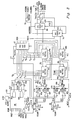
- the break-loose circuit 30 takes advantage of two signals generated by the accelerometer servo systems present in the motor drive electronics module.
- Each robot 20, 20′, for example, shown in Fig. 1, is provided with accelerometers 32 and 34 for detecting acceleration respectively in the x and y directions.
- the accelerometers generate signals representative of the magnitude and direction of acceleration.
- a difference circuit 36, 38 for the respective x and y directions compare the actual acceleration measured by the accelerometers 32 and 34 with the commanded acceleration values developed by the CPU 31 which applies the command values to different circuits through a bus 40.
- the two signals developed by the difference circuits 36 and 38 and referred to as Xcontrol and Ycontrol indicate, by amplitude, the difference between the command acceleration and the actual acceleration for the x and y axes.
- the Xcontrol and Ycontrol signals are dual voltage signals ranging in amplitude from -15 to +15 volts.
- the negative component of the Xcontrol signal quantifies the acceleration error in the -X direction and conversely, the positive component of the Xcontrol signal quantifies acceleration error in th +X direction. The same relationship holds true for the Ycontrol signal
- the input of the Xcontrol and Ycontrol signals from the difference circuits 36 and 38 is buffered and scaled by an X axis input amplifier and a Y axis input amplifier 42 and 44, respectively.
- Amplifiers 42 and 44 are high impedance buffers designed to minimize the effect of connecting to signals in the motor drive electronics module.
- Amplifiers 42 and 44 scale the input amplitude of the Xcontrol and Ycontrol signals to an amplitude range compatible with the comparator logic of the break-loose detection circuitry 30.
- the scaled Xcontrol and Ycontrol signals are checked by the X axis and Y axis voltage comparator logic forming part of the break-loose circuitry to insure that the signal amplitude falls within the programmed safe limits.
- the amplitudes of the Xcontrol and Ycontrol signals represents the quantity of acceleration error.
- the signal voltage comparator logic is programmed, by way of voltage limits, to detect motor acceleration errors which exceed the voltage limits set which voltage limits are controlled by the preprogrammed computer system and applied to control the comparator logic by way of CPU 31 coupled to the X and Y axis voltage comparator logic by bus 40, according to the parameters of the particular job.
- the voltage comparator logic consists of four sections:
- the values programmed into the positive and negative voltage limits vary according to the acceleration profiles set for the XY motor, and the size of the arm payload mounted on the arm flange.
- the programmability of the voltage limits allows the system to vary the break-loose circuit sensitivity according to the changing dynamics of the arm acceleration, speed and payload.
- the ability to change the break-loose circuit parameters is important when the dynamics of the motion of the robot arm can change from operation to operation within the job. For example, an arm moving with a heavier tool reacts more slowly to acceleration than an arm having a lighter tool or no tool at all, thus necessitating the setting of reduced limiting values in order to properly monitor the heavier robot arm, for example.
- the X and Y axes pulse width discriminators 50 and 52 determine the minimum duration, in milliseconds, of the X and Y break-loose signal generated by the X and Y axis comparator logic circuits which generate a break-loose interrupt signal.
- Each pulse width discriminator can be programmed to allow minimum pulse widths from one to 255 milliseconds, for example, before generating a break-loose interrupt signal.
- Each pulse width discriminator serves essentially as a "filter” which bypasses (i.e. ignores) outputs of the voltage comparator logic that are not actual break-loose related errors.
- the pulse width discriminator is necessary to distinguish, under varying motion dynamics, a real stall (or break-loose) condition as opposed to conditions due to noise induced by mechanical coupling with another axis on the robot arm or expected initial acceleration errors resulting from high acceleration profiles.
- the value programmed into the pulse width discriminator by way of CPU 31 and bus 40 will vary according to the acceleration profiles set for the XY motor, the size of the robot arm payload and the mechanical coupling characteristic of the gripper or tool mechanics mounted upon the robot arm flange.
- the programmability of each discriminator allows the controller to vary the break-loose circuit sensitivity according to the changing dynamics of the arm acceleration speed and payload.
- the ability to change the break-loose circuit parameters is important since the dynamics of the motion of the robot arm can change significantly from operation to operation within the job.
- X and Y axes break interrupt latches 54 and 56 are coupled to the outputs of the discriminators 50 and 52, respectively and are set when triggered by a valid signal from their associated pulse width discriminator.
- the interrupt latches remain active even though the trigger signal may disappear until the controller responds to the system emergency interrupt. More specifically, CPU 31 receives a very high priority interrupt signal and responds to this emergency break-loose interrupt by turning off moving power and turning off all robot air bearings. After the moving components of the system are halted by the emergency condition and the robots are locked in place against the platen, due to the permanent magnet of each linear motor which is attracted to the platen, the interrupt latches are reset and reactivated in readiness to detect future break-loose conditions.
- the X and Y break interrupt buffers 54 and 56 include latches which enable the system to determine the specific source of the break-loose error condition.
- the system emergency interrupt generator 58 is responsible for detecting the occurrence of a X or Y break-loose signal from the interrupt latches and driving the active system emergency interrupt signal on bus 40.
- the system emergency interrupt signal triggers a high level hardware interrupt in the controller hardware logic.
- the requested move will be in the +X direction for a distance of twelve inches.
- robot arm 20 collides with an obstacle, stalls and begins to slide out-of-control.
- the break-loose circuit 30 has been set to an 11.5 positive voltage limit, an 11.5 negative voltage limit, and a 40 millisecond minimum pulse width discriminator value.
- Analog converter 60a couples the negative window value of -11.5 volts through operational amplifier 60c to the negative window reference inputs of the X axis and Y axis comparator logic and specifically the non-inverting inputs of comparators 60e and 60g.
- digital to analog converter 60b applies, through operational amplifier 60d, the positive window limits of +11.5 volts to the inverting inputs of comparator 60f and 60h.
- CPU 31 further applies a binary word at the inputs WD9 through WD15, as well as a control signal to input WDB to a control circuit 62 forming part of the pulse width discriminator circuits 50 and 52 for respectively applying binary control signals to first and second counters 64 and 66 each comprised of counter stages 64a, 64b and 66a, 66b respectively.
- the binary control signals applied to the two-stage counters 64 and 66 determine the number of clock pulses, i.e. the number of milliseconds which counters 64 and 66 will count before detecting the presence of a persistent break-loose condition of a predetermined minimum time interval.
- Clock pulses are applied to the clock input terminals of each of the counter stages from a master clock (MCLK), typically forming part of the CPU. For purposes of the present example, a 40 millisecond minimum pulse width discriminator value has been set into counters 64 and 66.
- the system analyzes the move request for access limit violations and anti-collision violations.
- the anti-collision techniques is one in which determination is made of the requested move to assure that performance of the move will not result in a collision. This collision detect technique is described in detail in copending Application Serial No. , filed and assigned to the assignee of the present invention (Megamation 3.0-006). If a potential collision condition is detected, the move request will be denied.
- the move is initiated and the XY motor controller sets the command acceleration value which is applied to both the robot linear motors for XY drive and to the XY difference circuits 36 and 38.
- the difference circuitry develops an acceleration error signal (the difference between the command value and the actual acceleration determined by the accelerometer), identified in Fig. 3 as the Xcontrol and the Ycontrol signals which are applied to the amplifiers 68 and 70 shown in block diagram form as 42 and 44 in Fig. 2.
- the Xcontrol signal indicates no errors and is well within the voltage limits set for the voltage comparator logic. This is determined by the Xcontrol signal which is applied to comparators 60e and 60f to be respectively compared against the negative and positive window values respectively applied to the non-inverting and inverting inputs of comparators 60e and 60f.
- the robot After moving six inches, the robot experiences a sudden deceleration caused by a collision. This condition is detected by the XY motor accelerometers 32 and 34 applying maximum amplitude acceleration error signal of +15 volts to the Xcontrol signal circuit, for example.
- the voltage comparator logic detects the +15 volt Xcontrol signal which has exceeded the preprogrammed +11.5 volt limit and issues an active break indication from comparator 60f through ORgate 60g.
- the X axis pulse width discriminator 64 upon receiving the active break indication from the X axis comparator logic, starts timing the duration of the active break signal, developing a count of the clock pulses applied to the clock pulse input. Due to the programmed setting of counter 64 by CPU 31, when the counter reaches a count of 40 milliseconds and the break signal XBREAK is still active, then an active signal is sent to the XBREAK interrupt latch 70 which may, for example, be a D-type flip-flop. Latch 68 is set active, thereby locking active the break condition even if the active signal from the pulse width discriminator 64 later becomes inactive.
- the system emergency interrupt generator comprising an ORgate 72 and inverter 74, receives an active XBREAK signal and generates a system emergency interrupt applied to the system bus 40.
- the system bus hardware interrupt causes the CPU to stop its current task and immediately execute a program task which shuts down all moving power and shuts down the air bearing of each arm.
- the power control circuit 76 is coupled to CPU 31 through bus 40, as shown for example, in Fig. 2.
- the permanent magnet in each robot "locks" the robot to the platen.
- CPU 31 accesses the interrupt buffer in each robot arm to determine which one has caused the break-loose emergency interrupt. An error message is developed on the touchscreen display to identify the arm which caused the break-loose emergency interrupt.
- the break-loose detection circuit of the present invention provides a safety and control characteristic for each robot arm which is unique to the system of Fig. 1 and which sets the system far apart from other conventional two axis linear motor implementations.
- the importance of the break-loose technique in the implementation of two axis linear motors in the robot system of Fig. 1 include the following:
- the components employed in the circuit shown in Fig. 2 and Fig. 3 may, for example, be the following: CIRCUIT MODEL/TYPE MANUFACTURER 60 AD7528 AD587 AD581 Analog Devices 68, 70 LM741 National Semiconductor 60e, 60f, 60g, 60h LM148 National Semiconductor 60i, 60k, 72, 74LS532 Texas Instruments 64a, 64b, 64c, 64d HCT163 RCA 62 HCT564 RCA 68, 70 74HCT74 RCA 74 74OG RCA 76 74HCTOB RCA 32, 34 Accelerometer Xynetics 36, 38 Difference Circuit Xynetics 31 CPU 68020 Motorola
Landscapes
- Engineering & Computer Science (AREA)
- Human Computer Interaction (AREA)
- Manufacturing & Machinery (AREA)
- Physics & Mathematics (AREA)
- General Physics & Mathematics (AREA)
- Automation & Control Theory (AREA)
- Manipulator (AREA)
- Control Of Linear Motors (AREA)
- Numerical Control (AREA)
- Control Of Vehicles With Linear Motors And Vehicles That Are Magnetically Levitated (AREA)
Applications Claiming Priority (2)
| Application Number | Priority Date | Filing Date | Title |
|---|---|---|---|
| US07/394,622 US5081593A (en) | 1989-08-16 | 1989-08-16 | Method and apparatus for monitoring and controlling linear motor robot apparatus and the like |
| US394622 | 1989-08-16 |
Publications (3)
| Publication Number | Publication Date |
|---|---|
| EP0414643A2 true EP0414643A2 (fr) | 1991-02-27 |
| EP0414643A3 EP0414643A3 (en) | 1992-08-12 |
| EP0414643B1 EP0414643B1 (fr) | 1997-07-23 |
Family
ID=23559743
Family Applications (1)
| Application Number | Title | Priority Date | Filing Date |
|---|---|---|---|
| EP90810620A Expired - Lifetime EP0414643B1 (fr) | 1989-08-16 | 1990-08-16 | Méthode et appareil pour la commande et la surveillance d'appareil robot à moteur linéaire |
Country Status (5)
| Country | Link |
|---|---|
| US (1) | US5081593A (fr) |
| EP (1) | EP0414643B1 (fr) |
| JP (1) | JPH03235602A (fr) |
| AT (1) | ATE155901T1 (fr) |
| DE (1) | DE69031098D1 (fr) |
Cited By (3)
| Publication number | Priority date | Publication date | Assignee | Title |
|---|---|---|---|---|
| EP0589668A1 (fr) * | 1992-09-21 | 1994-03-30 | Pitney Bowes Inc. | Système de détection de calage pour un moteur é courant continu |
| EP0822387A3 (fr) * | 1996-07-31 | 1999-01-13 | Carl Zeiss | Appareil de mesure de coordonnées avec protection de collision |
| WO2023285637A1 (fr) | 2021-07-16 | 2023-01-19 | Roche Diagnostics Gmbh | Dispositif de transfert pour transférer des récipients à échantillons dans un système de manipulation d'échantillons |
Families Citing this family (14)
| Publication number | Priority date | Publication date | Assignee | Title |
|---|---|---|---|---|
| US5542501A (en) * | 1991-12-10 | 1996-08-06 | Mitsubishi Denki Kabushiki Kaisha | Apparatus for controlling an elevator to reduce vibrations created in a linear drive motor |
| US5386621A (en) * | 1993-08-16 | 1995-02-07 | Ford Motor Company | Flexible assembly cell |
| GB2287045B (en) * | 1994-03-04 | 1997-05-14 | Joseph Michael | Programmable materials |
| JPH08300280A (ja) * | 1995-05-09 | 1996-11-19 | Fanuc Ltd | ロボットの動作制御方式 |
| US6771176B2 (en) * | 1998-05-29 | 2004-08-03 | William Jude Wilkerson | Acceleration monitoring and safety data accounting system for motor vehicles and other types of equipment |
| US6265839B1 (en) * | 1999-11-10 | 2001-07-24 | Howard Layton | Hoist transfer drive system having X and Y-linear motors |
| JP2003133200A (ja) * | 2001-10-19 | 2003-05-09 | Canon Inc | シミュレーション装置及びシミュレーション方法 |
| DE10304019A1 (de) * | 2003-02-01 | 2004-11-04 | Kuka Roboter Gmbh | Verfahren zum Überwachen einer Maschine und derartige Maschine, insbesondere Roboter |
| WO2007057390A2 (fr) * | 2005-11-16 | 2007-05-24 | Abb Ab | Procede et dispositif servant a commander le mouvement d'un robot industriel |
| JP5181954B2 (ja) * | 2008-09-12 | 2013-04-10 | 株式会社安川電機 | ロボットシステムの異常検出方法、ロボットシステム、ステージシステムの異常検出方法、ステージシステム、および、半導体製造装置 |
| US8384442B2 (en) | 2010-07-22 | 2013-02-26 | Wayne F. Salhany | Integrated circuit signal generation device |
| US9962833B2 (en) | 2015-04-07 | 2018-05-08 | Mtm Robotics, Llc | System and method for adjusting end-effector actuation based on relative position with respect to gravitational force |
| US9981383B1 (en) * | 2016-08-02 | 2018-05-29 | X Development Llc | Real-time trajectory generation for actuators of a robot to reduce chance of collision with obstacle(s) |
| US10369679B2 (en) * | 2016-11-09 | 2019-08-06 | The Boeing Company | Apparatus, system and method for performing automated finishing operations on a workpiece |
Family Cites Families (19)
| Publication number | Priority date | Publication date | Assignee | Title |
|---|---|---|---|---|
| US3851196A (en) * | 1971-09-08 | 1974-11-26 | Xynetics Inc | Plural axis linear motor structure |
| JPS5136441B2 (fr) * | 1972-09-08 | 1976-10-08 | ||
| US3886383A (en) * | 1974-04-01 | 1975-05-27 | Rohr Industries Inc | Compressed back iron linear motor laminated core |
| JPS52129155A (en) * | 1976-04-19 | 1977-10-29 | Tokico Ltd | Information reader of playback robbot |
| CA1121888A (fr) * | 1977-04-30 | 1982-04-13 | Junichi Ikeda | Robot industriel |
| US4161787A (en) * | 1977-11-04 | 1979-07-17 | Motorola, Inc. | Programmable timer module coupled to microprocessor system |
| JPS57189752A (en) * | 1981-05-14 | 1982-11-22 | Fanuc Ltd | Main shaft rotation speed check system |
| US4510426A (en) * | 1982-07-30 | 1985-04-09 | Lectron Products, Inc. | Memory power seat controller |
| US4667697A (en) * | 1985-04-08 | 1987-05-26 | Armco, Inc. | Unitized check valve |
| SU1405023A1 (ru) * | 1985-04-08 | 1988-06-23 | Дальневосточный политехнический институт им.В.В.Куйбышева | Устройство дл управлени приводом робота |
| US4706007A (en) * | 1985-06-25 | 1987-11-10 | Kabushiki Kaisha Yaskawa Denki Seisakusho | Surface pulse motor |
| JPS6224305A (ja) * | 1985-07-24 | 1987-02-02 | Hitachi Ltd | 産業用ロボツトのサ−ボ異常検出方法 |
| US4718078A (en) * | 1985-08-19 | 1988-01-05 | Siemens Aktiengesellschaft | System for controlling motion of a robot |
| JPS62133605A (ja) * | 1985-12-04 | 1987-06-16 | 富士通株式会社 | 絶縁膜形成方法 |
| US4835424A (en) * | 1987-03-23 | 1989-05-30 | Megamation Incorporated | Platen laminated in mutually perpendicular direction for use with linear motors and the like |
| JPS63245388A (ja) * | 1987-03-30 | 1988-10-12 | フアナツク株式会社 | 産業ロボットにおける運動の阻害事態の警報装置 |
| US4823062A (en) * | 1987-07-23 | 1989-04-18 | Megamation, Incorporated | Method and apparatus for precision control of linear motors and the like employing a closed loop technique |
| US4890241A (en) * | 1987-10-26 | 1989-12-26 | Megamation Incorporated | Robotic system |
| US4958115A (en) * | 1988-11-28 | 1990-09-18 | At&T Bell Laboratories | Capacitively commutated brushless DC servomotors |
-
1989
- 1989-08-16 US US07/394,622 patent/US5081593A/en not_active Expired - Fee Related
-
1990
- 1990-08-16 DE DE69031098T patent/DE69031098D1/de not_active Expired - Lifetime
- 1990-08-16 AT AT90810620T patent/ATE155901T1/de not_active IP Right Cessation
- 1990-08-16 EP EP90810620A patent/EP0414643B1/fr not_active Expired - Lifetime
- 1990-08-16 JP JP2216469A patent/JPH03235602A/ja active Pending
Cited By (3)
| Publication number | Priority date | Publication date | Assignee | Title |
|---|---|---|---|---|
| EP0589668A1 (fr) * | 1992-09-21 | 1994-03-30 | Pitney Bowes Inc. | Système de détection de calage pour un moteur é courant continu |
| EP0822387A3 (fr) * | 1996-07-31 | 1999-01-13 | Carl Zeiss | Appareil de mesure de coordonnées avec protection de collision |
| WO2023285637A1 (fr) | 2021-07-16 | 2023-01-19 | Roche Diagnostics Gmbh | Dispositif de transfert pour transférer des récipients à échantillons dans un système de manipulation d'échantillons |
Also Published As
| Publication number | Publication date |
|---|---|
| JPH03235602A (ja) | 1991-10-21 |
| DE69031098D1 (de) | 1997-09-04 |
| ATE155901T1 (de) | 1997-08-15 |
| US5081593A (en) | 1992-01-14 |
| EP0414643A3 (en) | 1992-08-12 |
| EP0414643B1 (fr) | 1997-07-23 |
Similar Documents
| Publication | Publication Date | Title |
|---|---|---|
| US5081593A (en) | Method and apparatus for monitoring and controlling linear motor robot apparatus and the like | |
| US5440213A (en) | Collision detecting method using an observer | |
| EP0474881B1 (fr) | Procede de commande d'arret d'un robot industriel | |
| KR0144650B1 (ko) | 서보모터의 이상부하 검출 제어방법 | |
| JPS61143803A (ja) | ロボツトの制御装置 | |
| EP0464211B1 (fr) | Procede de detection de collisions utilisant un observateur | |
| JPS63145909A (ja) | 座標測定装置の制御法 | |
| US20050010324A1 (en) | Device and method for monitoring collisions of a machine component with a workpiece or another machine component | |
| Stolt et al. | Robotic force estimation using dithering to decrease the low velocity friction uncertainties | |
| EP0240570A1 (fr) | Systeme de commande d'acceleration et de deceleration pour robots a articulation horizontale | |
| JPH10143216A (ja) | 可動ユニットの衝突検出装置 | |
| JPH01310889A (ja) | 産業用ロボットの制御装置 | |
| JPH0341299A (ja) | 地震時に装置を停止させるための装置 | |
| CN111857058A (zh) | 用于监控多轴运动系统的轴的加速度的方法和设备 | |
| CN110560808A (zh) | 碰撞保护方法 | |
| JP3855629B2 (ja) | ロボットの干渉検出装置 | |
| JP4314741B2 (ja) | ワーク搬入確認装置 | |
| JPS63229293A (ja) | ロボツト動作異常検出装置 | |
| JPS6334086A (ja) | 産業用ロボツト | |
| JP3231122B2 (ja) | ロボット制御方法 | |
| JP3079837B2 (ja) | 数値制御装置 | |
| JPH0425386A (ja) | 産業用ロボットの制御方法 | |
| JPH03178721A (ja) | 数値制御工作機械の同期タッピング装置 | |
| JPH106185A (ja) | 工具破損検出方法及び装置 | |
| JP2001016723A (ja) | ガス遮断器用ドッキング装置 |
Legal Events
| Date | Code | Title | Description |
|---|---|---|---|
| PUAI | Public reference made under article 153(3) epc to a published international application that has entered the european phase |
Free format text: ORIGINAL CODE: 0009012 |
|
| AK | Designated contracting states |
Kind code of ref document: A2 Designated state(s): AT CH DE ES FR GB IT LI SE |
|
| 17P | Request for examination filed |
Effective date: 19910814 |
|
| PUAL | Search report despatched |
Free format text: ORIGINAL CODE: 0009013 |
|
| AK | Designated contracting states |
Kind code of ref document: A3 Designated state(s): AT CH DE ES FR GB IT LI SE |
|
| 17Q | First examination report despatched |
Effective date: 19940706 |
|
| GRAG | Despatch of communication of intention to grant |
Free format text: ORIGINAL CODE: EPIDOS AGRA |
|
| GRAH | Despatch of communication of intention to grant a patent |
Free format text: ORIGINAL CODE: EPIDOS IGRA |
|
| GRAH | Despatch of communication of intention to grant a patent |
Free format text: ORIGINAL CODE: EPIDOS IGRA |
|
| GRAA | (expected) grant |
Free format text: ORIGINAL CODE: 0009210 |
|
| AK | Designated contracting states |
Kind code of ref document: B1 Designated state(s): AT CH DE ES FR GB IT LI SE |
|
| PG25 | Lapsed in a contracting state [announced via postgrant information from national office to epo] |
Ref country code: IT Free format text: LAPSE BECAUSE OF FAILURE TO SUBMIT A TRANSLATION OF THE DESCRIPTION OR TO PAY THE FEE WITHIN THE PRE;WARNING: LAPSES OF ITALIAN PATENTS WITH EFFECTIVE DATE BEFORE 2007 MAY HAVE OCCURRED AT ANY TIME BEFORE 2007. THE CORRECT EFFECTIVE DATE MAY BE DIFFERENT FROM THE ONE RECORDED.SCRIBED TIME-LIMIT Effective date: 19970723 Ref country code: AT Effective date: 19970723 Ref country code: LI Free format text: LAPSE BECAUSE OF FAILURE TO SUBMIT A TRANSLATION OF THE DESCRIPTION OR TO PAY THE FEE WITHIN THE PRESCRIBED TIME-LIMIT Effective date: 19970723 Ref country code: CH Free format text: LAPSE BECAUSE OF FAILURE TO SUBMIT A TRANSLATION OF THE DESCRIPTION OR TO PAY THE FEE WITHIN THE PRESCRIBED TIME-LIMIT Effective date: 19970723 Ref country code: FR Effective date: 19970723 |
|
| REF | Corresponds to: |
Ref document number: 155901 Country of ref document: AT Date of ref document: 19970815 Kind code of ref document: T |
|
| REG | Reference to a national code |
Ref country code: CH Ref legal event code: EP |
|
| PGFP | Annual fee paid to national office [announced via postgrant information from national office to epo] |
Ref country code: ES Payment date: 19970821 Year of fee payment: 8 |
|
| REF | Corresponds to: |
Ref document number: 69031098 Country of ref document: DE Date of ref document: 19970904 |
|
| PG25 | Lapsed in a contracting state [announced via postgrant information from national office to epo] |
Ref country code: SE Effective date: 19971023 Ref country code: GB Free format text: LAPSE BECAUSE OF NON-PAYMENT OF DUE FEES Effective date: 19971023 |
|
| PG25 | Lapsed in a contracting state [announced via postgrant information from national office to epo] |
Ref country code: DE Effective date: 19971024 |
|
| EN | Fr: translation not filed | ||
| PG25 | Lapsed in a contracting state [announced via postgrant information from national office to epo] |
Ref country code: ES Free format text: LAPSE BECAUSE OF FAILURE TO SUBMIT A TRANSLATION OF THE DESCRIPTION OR TO PAY THE FEE WITHIN THE PRESCRIBED TIME-LIMIT Effective date: 19980122 |
|
| REG | Reference to a national code |
Ref country code: CH Ref legal event code: PL |
|
| PLBE | No opposition filed within time limit |
Free format text: ORIGINAL CODE: 0009261 |
|
| STAA | Information on the status of an ep patent application or granted ep patent |
Free format text: STATUS: NO OPPOSITION FILED WITHIN TIME LIMIT |
|
| GBPC | Gb: european patent ceased through non-payment of renewal fee |
Effective date: 19971023 |
|
| 26N | No opposition filed |