EP0589668A1 - Système de détection de calage pour un moteur é courant continu - Google Patents
Système de détection de calage pour un moteur é courant continu Download PDFInfo
- Publication number
- EP0589668A1 EP0589668A1 EP93307448A EP93307448A EP0589668A1 EP 0589668 A1 EP0589668 A1 EP 0589668A1 EP 93307448 A EP93307448 A EP 93307448A EP 93307448 A EP93307448 A EP 93307448A EP 0589668 A1 EP0589668 A1 EP 0589668A1
- Authority
- EP
- European Patent Office
- Prior art keywords
- motor
- count
- proceed
- microcontroller
- time interval
- Prior art date
- Legal status (The legal status is an assumption and is not a legal conclusion. Google has not performed a legal analysis and makes no representation as to the accuracy of the status listed.)
- Granted
Links
Images

Classifications
-
- G—PHYSICS
- G05—CONTROLLING; REGULATING
- G05B—CONTROL OR REGULATING SYSTEMS IN GENERAL; FUNCTIONAL ELEMENTS OF SUCH SYSTEMS; MONITORING OR TESTING ARRANGEMENTS FOR SUCH SYSTEMS OR ELEMENTS
- G05B19/00—Program-control systems
- G05B19/02—Program-control systems electric
- G05B19/18—Numerical control [NC], i.e. automatically operating machines, in particular machine tools, e.g. in a manufacturing environment, so as to execute positioning, movement or co-ordinated operations by means of program data in numerical form
- G05B19/406—Numerical control [NC], i.e. automatically operating machines, in particular machine tools, e.g. in a manufacturing environment, so as to execute positioning, movement or co-ordinated operations by means of program data in numerical form characterised by monitoring or safety
- G05B19/4062—Monitoring servoloop, e.g. overload of servomotor, loss of feedback or reference
-
- H—ELECTRICITY
- H02—GENERATION; CONVERSION OR DISTRIBUTION OF ELECTRIC POWER
- H02H—EMERGENCY PROTECTIVE CIRCUIT ARRANGEMENTS
- H02H7/00—Emergency protective circuit arrangements specially adapted for specific types of electric machines or apparatus or for sectionalised protection of cable or line systems, and effecting automatic switching in the event of an undesired change from normal working conditions
- H02H7/08—Emergency protective circuit arrangements specially adapted for specific types of electric machines or apparatus or for sectionalised protection of cable or line systems, and effecting automatic switching in the event of an undesired change from normal working conditions for dynamo-electric motors
- H02H7/093—Emergency protective circuit arrangements specially adapted for specific types of electric machines or apparatus or for sectionalised protection of cable or line systems, and effecting automatic switching in the event of an undesired change from normal working conditions for dynamo-electric motors against increase beyond, or decrease below, a predetermined level of rotational speed
-
- Y—GENERAL TAGGING OF NEW TECHNOLOGICAL DEVELOPMENTS; GENERAL TAGGING OF CROSS-SECTIONAL TECHNOLOGIES SPANNING OVER SEVERAL SECTIONS OF THE IPC; TECHNICAL SUBJECTS COVERED BY FORMER USPC CROSS-REFERENCE ART COLLECTIONS [XRACs] AND DIGESTS
- Y10—TECHNICAL SUBJECTS COVERED BY FORMER USPC
- Y10S—TECHNICAL SUBJECTS COVERED BY FORMER USPC CROSS-REFERENCE ART COLLECTIONS [XRACs] AND DIGESTS
- Y10S388/00—Electricity: motor control systems
- Y10S388/90—Specific system operational feature
- Y10S388/903—Protective, e.g. voltage or current limit
-
- Y—GENERAL TAGGING OF NEW TECHNOLOGICAL DEVELOPMENTS; GENERAL TAGGING OF CROSS-SECTIONAL TECHNOLOGIES SPANNING OVER SEVERAL SECTIONS OF THE IPC; TECHNICAL SUBJECTS COVERED BY FORMER USPC CROSS-REFERENCE ART COLLECTIONS [XRACs] AND DIGESTS
- Y10—TECHNICAL SUBJECTS COVERED BY FORMER USPC
- Y10S—TECHNICAL SUBJECTS COVERED BY FORMER USPC CROSS-REFERENCE ART COLLECTIONS [XRACs] AND DIGESTS
- Y10S388/00—Electricity: motor control systems
- Y10S388/907—Specific control circuit element or device
Definitions
- the present invention relates to a DC motor servo system utilizing an application specific integrated circuit (ASIC) under the influence of a microcomputer for controlling a DC motor.
- ASIC application specific integrated circuit
- a DC motor is employed as a prime mover.
- One such system is novel mail processing system.
- the mail processing system has employs a plurality of system modules for processing envelopes Particularly, the mail processing system includes a feeder section having a envelope stack receiving module, a singulation module, a envelope flap moistening module.
- the feeder section is followed by a mailing machine section having a integral scale module, tape module, meter module and transport module.
- the mail processing of particular interest offers the advantage of providing a minimum foot print and high through-put rate.
- the microcomputer system In order to achieve this advantage, realizing that the mail processing system most accommodate a variety of sized envelope, it is necessary for the microcomputer system to exercise exacting servo control over the motors associated with one or more of the modules.
- a system constraint In order to achieve the high through-put rate in light of the minimum feed path (foot print), a system constraint is to accommodate maximum acceleration and deceleration of a respective motor under system loads without destructively over-driving the motor.
- a method of detecting a motor stall condition under the control of a programmable microcontroller and a motor controller comprising the following steps carried out under the control of the program in the microcontroller for each time interval T:
- a microcontroller is in bus communication with a Motor Control System Application Specific Integrated Circuit (MCS ASIC).
- MCS ASIC Motor Control System Application Specific Integrated Circuit
- the MCS ASIC is under the direction of the motor controller for servo-controlling a plurality of motors.
- the MCS ASIC servo-controls each motor to provide individual servo-control, the controller algorithm for each motor can be independently changed on the fly and the servo-rate for each motor is independently selectable.
- each motor is subject the control of a stall-detection algorithm. In response to the stall-detection algorithm, the motor controller will shut down the necessary module system motor to prevent motor destruction.
- the MCS ASIC is a digital component designed to provide high-performance servo control for de motors. It operates as a peripheral device under the control of a host microprocessor which, in the preferred environment, is a mailing system controller.
- the motor controller performs digital filtering for closed-loop compensation.
- the respective input channels of the MCS ASIC transforms the signals from a respective motor position encoder into a digital word through a quadrature decoder and up/down counter, and the respective output channels transforms the filter digital output into a pulse-width modulated (PWM) signal.
- PWM pulse-width modulated
- An output from the up/down is directed to the microcontroller where a position error of zero results in to a motor command of zero, while a large sampled position error results to a large motor command magnitude.
- the position error is the difference between the desired angular position and the sampled actual motor shaft position as provided by and incremental position encoder. Therefore, a stall condition exists when the motor actual angular position lags the desired position excessively as the motion profile generator algorithm incrementally computes the next sampling interval's position command.
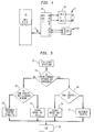
- Fig. 1 is diagram of the host motor controller, MCS ASIC and motor driver in accordance with the present invention.
- Fig. 2 is a schematic of a motor control system in accordance with the present invention.
- Fig. 3 is a logic flow representation of the stall logic of the microcontroller.
- the motor control system is comprised of a microcontroller 12 which is in bus 13 communication with a MCS ASIC 15.
- the MCS ASIC 15 controls eight separate motors 17 through a respective conventional amplifier 19.
- Each motor 17 is in communication with an encoder 21 in any suitable manner.
- the encoder 21 output is directed to the MCS ASIC 15.
- the host microcontroller 12 is programmed within a motion profile control module 20 to generate a motion profile for the motor 17 divisible in T- intervals.
- the output motor position command of the motion profile control module 20 is directed to a digital servo-control 24 through a sum junction 22.
- the output of the sum junction 22 is representative of the motor position error between a desired position and the actual position of the motor 17.
- the position error output of the sum junction 22 is directed to a digital servo-control 24 which issues the motor command.
- the motor command output from the digital servo-control 24 is directed to a stall/fault detection module 26 of the microcontroller 12 and to the MCS ASIC 15 position command register 30 over bus 13 every T-interval.
- the MCS ASIC 15 includes the position command register 30 of which the output is directed to a digital filter 32 through a sum junction 34.
- the output of the digital filter 32 is directed to a motor command register 36.
- the motor command register outputs a motor command direction signal to the amplifier 19.
- a pulse width modulator 38 obtains information from the motor command register from which the pufse width modulator 38 issues PWM signals to the amplifier 19.
- the MCS ASIC 15 also includes a input signal digital filter 40 which receives the output signals from the position encoder 21.
- the output of the input signal digital filter 40 is directed to a quadrature decoder 42.
- the output of the quadrature decoder 42 is directed to an up/down counter 44.
- the output of the up/down counter 44 is directed to position feedback register 46 which directs an output signal to the sum junction 34.
- the motor command signals from the motor controller 12 are received in the position command register 30 which signals are compared to the signals from the position feedback register 46.
- the output from the sum junction 34 is representative of the position difference. That difference is received by the digital filter 32 which generates a new position command which is stored in the motor command register.
- the output from the encoder 21 translated to a digital position word by the input signal digital filter, the quadrature decoder 42, and the up/down counter 44.
- the output of the up/down counter 44 is directed to the sum junction 22 of the microcontroller 12 to determine the position error as noted above.
- the MCS ASIC is a programmed device having a programmed microprocessing system specifically programmed with a particular control algorithm for each of a plurality of motors 19.
- the respective motor control algorithms are executed in the digital filter 32.
- the motor algorithm includes parameters stored in a parameter register (not shown) on the MIC ASIC which can be accessed by the microcontroller 12 such that the motor control algorithm can be changed on the fly.
- the stall/detection program module 26 is programmed to enter a routine at each T-interval 50.
- the motor command which is based on the determined position error is compared to a desired average threshold amount (also called herein: average stall threshold value "ASV").
- the average threshold amount represents a time dependent average of the position error which is less than the motor destruction amount for the particular motor 17 as prescribed by the motor manufacturer.
- a programmed time counter is compared to a programmed maximum count. Again the maximum count is a prescribed parameter by the motor manufacturer. If the time count is equal to the maximum count, the motor is determined "OK" at logic block 54 and the routine is ended for that T-interval at block 56. At decision block 52, if the time count is not equal to the maximum count the program count is incremented to a maximum count "N" at logic block 58 and the routine is ended at logic block 56 for that T-interval. It is noted that N multiplied by T equals maximum time before motor destruction in micro seconds.
- the time count is tested at decision block 60 to see if the count is equal to zero. If the time counter is non-zero, the counter is decremented at logic block 62 and the routine is ended at 56. If at logic block 60 the counter has been decremented to zero, a motor stall state is declared at logic block 64 and the routine is ended at 56. Once a motor stall is declared the microcontroller has the option of taking appropriate corrective action. In the preferred embodiment, that corrective action is stopping operation of a motor control system of a mail processing system.
Landscapes
- Engineering & Computer Science (AREA)
- Human Computer Interaction (AREA)
- Manufacturing & Machinery (AREA)
- Physics & Mathematics (AREA)
- General Physics & Mathematics (AREA)
- Automation & Control Theory (AREA)
- Control Of Electric Motors In General (AREA)
- Control Of Multiple Motors (AREA)
Applications Claiming Priority (2)
| Application Number | Priority Date | Filing Date | Title |
|---|---|---|---|
| US94760492A | 1992-09-21 | 1992-09-21 | |
| US947604 | 1992-09-21 |
Publications (3)
| Publication Number | Publication Date |
|---|---|
| EP0589668A1 true EP0589668A1 (fr) | 1994-03-30 |
| EP0589668B1 EP0589668B1 (fr) | 1997-05-07 |
| EP0589668B2 EP0589668B2 (fr) | 2003-06-04 |
Family
ID=25486401
Family Applications (1)
| Application Number | Title | Priority Date | Filing Date |
|---|---|---|---|
| EP93307448A Expired - Lifetime EP0589668B2 (fr) | 1992-09-21 | 1993-09-21 | Système de détection de calage pour un moteur é courant continu |
Country Status (4)
| Country | Link |
|---|---|
| US (1) | US5367236A (fr) |
| EP (1) | EP0589668B2 (fr) |
| CA (1) | CA2106450C (fr) |
| DE (1) | DE69310467T3 (fr) |
Cited By (3)
| Publication number | Priority date | Publication date | Assignee | Title |
|---|---|---|---|---|
| FR2768572A1 (fr) * | 1997-09-16 | 1999-03-19 | Eaton Sa Monaco | Actionneur pas-a-pas a detection de blocage |
| WO2001018935A1 (fr) * | 1999-09-03 | 2001-03-15 | Küster Automotive Door Systems GmbH | Procede pour reguler un dispositif de deplacement commande par un moteur electrique, par exemple pour un leve-vitres, et dispositif pour mettre en oeuvre ledit procede |
| US7215091B2 (en) * | 2003-01-03 | 2007-05-08 | Lexmark International, Inc. | Method for controlling a DC printer motor with a motor driver |
Families Citing this family (18)
| Publication number | Priority date | Publication date | Assignee | Title |
|---|---|---|---|---|
| US6226559B1 (en) * | 1995-12-14 | 2001-05-01 | Pitney Bowes Inc. | Method of providing real time machine control system particularly suited for a postage meter mailing machine |
| US6011376A (en) * | 1998-03-13 | 2000-01-04 | Cincinnati Milacron Inc. | Method and apparatus for injection molding machine control |
| US6593716B1 (en) * | 2000-11-21 | 2003-07-15 | Honeywell International Inc. | Circuit using current limiting to reduce power consumption of actuator with DC brush motor |
| ITTO20020735A1 (it) * | 2002-08-21 | 2004-02-22 | L G L Electronics Spa | Metodo di rilevazione dello stallo del motore del |
| US7486489B2 (en) * | 2003-05-13 | 2009-02-03 | Siemens Canada Limited | System and method for speed control and stall protection combination for electric motors such as in engine cooling applications |
| DE102004030130A1 (de) * | 2004-06-22 | 2006-01-19 | Robert Bosch Gmbh | Verfahren und Vorrichtung zur Blockiererkennung eines Gleichstrommotors |
| DE102007026344A1 (de) | 2007-06-06 | 2008-12-18 | Francotyp-Postalia Gmbh | Korrekturverfahren für eine mikroprozessor-gesteuerte digitale Regelung |
| GB0713239D0 (en) * | 2007-07-07 | 2007-08-15 | Trw Ltd | Electriv motor control |
| US8084982B2 (en) | 2008-11-18 | 2011-12-27 | Honeywell International Inc. | HVAC actuator with output torque compensation |
| US8264192B2 (en) | 2009-08-10 | 2012-09-11 | Emerson Climate Technologies, Inc. | Controller and method for transitioning between control angles |
| CN105529964B (zh) * | 2009-09-22 | 2020-06-05 | 艾默生电气公司 | 用于永磁电机的无传感器丢失/找到的转子检测 |
| US9815193B2 (en) | 2011-06-27 | 2017-11-14 | Delaware Capital Formation, Inc. | Electric motor based holding control systems and methods |
| US9634593B2 (en) | 2012-04-26 | 2017-04-25 | Emerson Climate Technologies, Inc. | System and method for permanent magnet motor control |
| KR101470225B1 (ko) * | 2013-10-22 | 2014-12-05 | 현대자동차주식회사 | 차량용 모터 구동 장치 |
| EP3071412B1 (fr) | 2013-11-21 | 2020-04-22 | Hewlett-Packard Development Company, L.P. | Caractérisation d'un moteur dans une imprimante |
| US20170099023A1 (en) * | 2014-05-29 | 2017-04-06 | Robert G. Attarian | Field control for permanent magnet dc motors |
| CN106330008B (zh) * | 2016-08-31 | 2019-09-20 | 惠州华阳通用电子有限公司 | 一种车载空调电机控制方法及装置 |
| DE102019108725A1 (de) * | 2019-04-03 | 2020-10-08 | Infineon Technologies Ag | Steuerung für einen sensorlosen elektromotor |
Citations (6)
| Publication number | Priority date | Publication date | Assignee | Title |
|---|---|---|---|---|
| GB2128425A (en) * | 1982-10-08 | 1984-04-26 | Newelec Pretoria | Stall detection apparatus |
| GB2157902A (en) * | 1984-04-17 | 1985-10-30 | Lucas Ind Plc | Windscreen wiper motor protection circuit |
| JPS6224305A (ja) * | 1985-07-24 | 1987-02-02 | Hitachi Ltd | 産業用ロボツトのサ−ボ異常検出方法 |
| US4725765A (en) * | 1985-11-18 | 1988-02-16 | Ford Motor Company | Method and apparatus for the protection of D.C. motors under stalled conditions |
| JPH02146992A (ja) * | 1988-11-25 | 1990-06-06 | Matsushita Electric Works Ltd | 電動機の制御装置 |
| EP0414643A2 (fr) * | 1989-08-16 | 1991-02-27 | Megamation Incorporated | Méthode et appareil pour la commande et la surveillance d'appareil robot à moteur linéaire |
Family Cites Families (18)
| Publication number | Priority date | Publication date | Assignee | Title |
|---|---|---|---|---|
| US4496890A (en) * | 1982-03-11 | 1985-01-29 | Gerard A. Wurdack & Associates, Inc. | Antenna rotator controller |
| US4467260A (en) * | 1983-04-20 | 1984-08-21 | Westinghouse Electric Corp. | Motor control apparatus with rotor heating protection |
| US4623826A (en) * | 1984-07-31 | 1986-11-18 | John Brown Inc. | Stall protection circuit for brushless motor control |
| US4630210A (en) * | 1984-10-04 | 1986-12-16 | Pitney Bowes Inc. | Microprocessor controlled d.c. motor for controlling a load |
| US4659976A (en) * | 1985-04-24 | 1987-04-21 | Dresser Industries, Inc. | Method and apparatus for maximizing utilization of an electric motor under load |
| US4875000A (en) * | 1986-11-26 | 1989-10-17 | The Babcock & Wilcox Company | Current fault detection system and method for AC controller |
| US4821203A (en) * | 1987-05-12 | 1989-04-11 | Marq Packaging Systems, Inc. | Computer adjustable case handling machine |
| US4829222A (en) * | 1987-08-19 | 1989-05-09 | Pitney Bowes Inc. | Stepper motor driver control circuit |
| DE3804679C2 (de) * | 1988-02-15 | 1993-12-02 | Bosch Gmbh Robert | Überlastschutz für Elektromotoren |
| US4983897A (en) * | 1988-08-05 | 1991-01-08 | Therm-O-Disc, Incorporated | Control circuit |
| US4985666A (en) * | 1988-08-30 | 1991-01-15 | Sony Corporation | Safety device for video cassette recorder |
| JP2737956B2 (ja) * | 1988-10-31 | 1998-04-08 | 松下電器産業株式会社 | ブラシレスモータのコイル焼損防止装置 |
| KR930011196B1 (ko) * | 1988-11-16 | 1993-11-25 | 롬 가부시끼가이샤 | 모터 구동회로 |
| US4980624A (en) * | 1989-12-22 | 1990-12-25 | Eaton Corporation | Adaptive overload protection of electric motors and static switching drives |
| US5028854A (en) * | 1990-01-30 | 1991-07-02 | The Pillsbury Company | Variable speed motor drive |
| US5012168A (en) * | 1990-02-20 | 1991-04-30 | Ford Motor Company | Method and apparatus for detecting stall current in an energized electric motor |
| US4999552A (en) * | 1990-02-27 | 1991-03-12 | The United States Of America As Represented By The Secretary Of The Air Force | Torque motor driver |
| US5017846A (en) * | 1990-04-05 | 1991-05-21 | General Electric Company | Stall protection circuit for an electronically commutated motor |
-
1993
- 1993-09-17 CA CA002106450A patent/CA2106450C/fr not_active Expired - Fee Related
- 1993-09-21 EP EP93307448A patent/EP0589668B2/fr not_active Expired - Lifetime
- 1993-09-21 DE DE69310467T patent/DE69310467T3/de not_active Expired - Fee Related
-
1994
- 1994-03-25 US US08/218,042 patent/US5367236A/en not_active Expired - Lifetime
Patent Citations (6)
| Publication number | Priority date | Publication date | Assignee | Title |
|---|---|---|---|---|
| GB2128425A (en) * | 1982-10-08 | 1984-04-26 | Newelec Pretoria | Stall detection apparatus |
| GB2157902A (en) * | 1984-04-17 | 1985-10-30 | Lucas Ind Plc | Windscreen wiper motor protection circuit |
| JPS6224305A (ja) * | 1985-07-24 | 1987-02-02 | Hitachi Ltd | 産業用ロボツトのサ−ボ異常検出方法 |
| US4725765A (en) * | 1985-11-18 | 1988-02-16 | Ford Motor Company | Method and apparatus for the protection of D.C. motors under stalled conditions |
| JPH02146992A (ja) * | 1988-11-25 | 1990-06-06 | Matsushita Electric Works Ltd | 電動機の制御装置 |
| EP0414643A2 (fr) * | 1989-08-16 | 1991-02-27 | Megamation Incorporated | Méthode et appareil pour la commande et la surveillance d'appareil robot à moteur linéaire |
Non-Patent Citations (2)
| Title |
|---|
| PATENT ABSTRACTS OF JAPAN vol. 011, no. 203 (P - 591) 2 July 1987 (1987-07-02) * |
| PATENT ABSTRACTS OF JAPAN vol. 014, no. 394 (E - 0969) 24 August 1990 (1990-08-24) * |
Cited By (5)
| Publication number | Priority date | Publication date | Assignee | Title |
|---|---|---|---|---|
| FR2768572A1 (fr) * | 1997-09-16 | 1999-03-19 | Eaton Sa Monaco | Actionneur pas-a-pas a detection de blocage |
| EP0908999A1 (fr) * | 1997-09-16 | 1999-04-14 | Eaton S.A.M. | Actionneur pas-à-pas à détection de blocage |
| WO2001018935A1 (fr) * | 1999-09-03 | 2001-03-15 | Küster Automotive Door Systems GmbH | Procede pour reguler un dispositif de deplacement commande par un moteur electrique, par exemple pour un leve-vitres, et dispositif pour mettre en oeuvre ledit procede |
| US6541930B1 (en) | 1999-09-03 | 2003-04-01 | Küster Automotive Door Systems GmbH | Method for controlling an adjustment device that is driven in an electromotorical manner and used for window lifters for instance and a device for carrying out said method |
| US7215091B2 (en) * | 2003-01-03 | 2007-05-08 | Lexmark International, Inc. | Method for controlling a DC printer motor with a motor driver |
Also Published As
| Publication number | Publication date |
|---|---|
| EP0589668B2 (fr) | 2003-06-04 |
| CA2106450A1 (fr) | 1994-03-22 |
| DE69310467T2 (de) | 1997-10-23 |
| US5367236A (en) | 1994-11-22 |
| DE69310467T3 (de) | 2004-08-26 |
| EP0589668B1 (fr) | 1997-05-07 |
| CA2106450C (fr) | 1997-05-27 |
| DE69310467D1 (de) | 1997-06-12 |
Similar Documents
| Publication | Publication Date | Title |
|---|---|---|
| US5367236A (en) | DC motor stall-detection system | |
| US4714867A (en) | Method and apparatus for controlling a stepper motor with a programmable parabolic velocity profile | |
| EP0224589B1 (fr) | Unite de commande d'entrainement pour une machine de moulage a injection entrainee par des servo-moteurs | |
| EP0242867A2 (fr) | Appareil de commande pour robot | |
| EP1417747B1 (fr) | Procede et appareil de reglage de la vitesse d'un moteur magnetique permanent haute performance a l'aide d'informations de position limitees | |
| EP0786710A1 (fr) | Système de positionnement avec mode de contrÔle en position et en vitesse utilisant profile de vitesse | |
| EP0347465B1 (fr) | procede de commande d'un servomoteur | |
| US5519297A (en) | Spindle positioning method | |
| EP0621085B2 (fr) | Dispositif de commande d'un système à microprocesseur appliqué à un système de traitement de courrier | |
| EP1345312B1 (fr) | Dispositif de commande pour commander un onduleur pour la commande d'un moteur à courant alternatif | |
| EP0241867A1 (fr) | Dispositif de régulation de l'accélération et de la décélération se référant aux valeurs de glissement | |
| EP0852347B1 (fr) | Procede de commande d'un servomoteur | |
| EP0287684A1 (fr) | Systeme de commande a reaction negative | |
| EP0616417B1 (fr) | Procede de commande d'un moteur a courant alternatif. | |
| JPS62180886A (ja) | エレベ−タ−の速度制御装置 | |
| JP3354633B2 (ja) | ステッピングモータ駆動装置 | |
| US4151448A (en) | Pulse motor driving system | |
| JP3126372B2 (ja) | モータ制御回路 | |
| US6169380B1 (en) | Acquisition of printed media with defined traction | |
| EP1164449A2 (fr) | Méthode et système pour déterminer le mouvement d'un moteur dans un système de vitre électrique de véhicule | |
| US12081159B2 (en) | Observer-based ripple detection for speed and position measurement for brushed direct current motors | |
| JPS63220786A (ja) | 電動機のデイジタル速度制御方法 | |
| KR0171837B1 (ko) | 센서레스 모터의 정지 방법 | |
| EP1081861A2 (fr) | Système de calibration de gain et procédé de création de convertisseurs A/N appariés | |
| KR950012012B1 (ko) | 디지탈 속도 제어기의 속도검출장치 |
Legal Events
| Date | Code | Title | Description |
|---|---|---|---|
| PUAI | Public reference made under article 153(3) epc to a published international application that has entered the european phase |
Free format text: ORIGINAL CODE: 0009012 |
|
| AK | Designated contracting states |
Kind code of ref document: A1 Designated state(s): CH DE FR GB LI |
|
| 17P | Request for examination filed |
Effective date: 19940901 |
|
| 17Q | First examination report despatched |
Effective date: 19951219 |
|
| GRAG | Despatch of communication of intention to grant |
Free format text: ORIGINAL CODE: EPIDOS AGRA |
|
| GRAH | Despatch of communication of intention to grant a patent |
Free format text: ORIGINAL CODE: EPIDOS IGRA |
|
| GRAH | Despatch of communication of intention to grant a patent |
Free format text: ORIGINAL CODE: EPIDOS IGRA |
|
| GRAA | (expected) grant |
Free format text: ORIGINAL CODE: 0009210 |
|
| AK | Designated contracting states |
Kind code of ref document: B1 Designated state(s): CH DE FR GB LI |
|
| PG25 | Lapsed in a contracting state [announced via postgrant information from national office to epo] |
Ref country code: LI Effective date: 19970507 Ref country code: CH Effective date: 19970507 |
|
| REG | Reference to a national code |
Ref country code: CH Ref legal event code: EP |
|
| REF | Corresponds to: |
Ref document number: 69310467 Country of ref document: DE Date of ref document: 19970612 |
|
| ET | Fr: translation filed | ||
| REG | Reference to a national code |
Ref country code: CH Ref legal event code: PL |
|
| PLBQ | Unpublished change to opponent data |
Free format text: ORIGINAL CODE: EPIDOS OPPO |
|
| PLBI | Opposition filed |
Free format text: ORIGINAL CODE: 0009260 |
|
| PLBF | Reply of patent proprietor to notice(s) of opposition |
Free format text: ORIGINAL CODE: EPIDOS OBSO |
|
| 26 | Opposition filed |
Opponent name: FRANCOTYP-POSTALIA AKTIENGESELLSCHAFT & CO. Effective date: 19980209 |
|
| PLBF | Reply of patent proprietor to notice(s) of opposition |
Free format text: ORIGINAL CODE: EPIDOS OBSO |
|
| PLAW | Interlocutory decision in opposition |
Free format text: ORIGINAL CODE: EPIDOS IDOP |
|
| APAC | Appeal dossier modified |
Free format text: ORIGINAL CODE: EPIDOS NOAPO |
|
| APAE | Appeal reference modified |
Free format text: ORIGINAL CODE: EPIDOS REFNO |
|
| APAC | Appeal dossier modified |
Free format text: ORIGINAL CODE: EPIDOS NOAPO |
|
| REG | Reference to a national code |
Ref country code: GB Ref legal event code: IF02 |
|
| PLAB | Opposition data, opponent's data or that of the opponent's representative modified |
Free format text: ORIGINAL CODE: 0009299OPPO |
|
| R26 | Opposition filed (corrected) |
Opponent name: FRANCOTYP POSTALIA AKTIENGESELLSCHAFT & CO. KG Effective date: 19980209 |
|
| APAC | Appeal dossier modified |
Free format text: ORIGINAL CODE: EPIDOS NOAPO |
|
| PLAW | Interlocutory decision in opposition |
Free format text: ORIGINAL CODE: EPIDOS IDOP |
|
| PUAH | Patent maintained in amended form |
Free format text: ORIGINAL CODE: 0009272 |
|
| STAA | Information on the status of an ep patent application or granted ep patent |
Free format text: STATUS: PATENT MAINTAINED AS AMENDED |
|
| 27A | Patent maintained in amended form |
Effective date: 20030604 |
|
| AK | Designated contracting states |
Designated state(s): CH DE FR GB LI |
|
| ET3 | Fr: translation filed ** decision concerning opposition | ||
| APAH | Appeal reference modified |
Free format text: ORIGINAL CODE: EPIDOSCREFNO |
|
| PGFP | Annual fee paid to national office [announced via postgrant information from national office to epo] |
Ref country code: GB Payment date: 20070926 Year of fee payment: 15 |
|
| PGFP | Annual fee paid to national office [announced via postgrant information from national office to epo] |
Ref country code: DE Payment date: 20071031 Year of fee payment: 15 |
|
| PGFP | Annual fee paid to national office [announced via postgrant information from national office to epo] |
Ref country code: FR Payment date: 20070917 Year of fee payment: 15 |
|
| GBPC | Gb: european patent ceased through non-payment of renewal fee |
Effective date: 20080921 |
|
| REG | Reference to a national code |
Ref country code: FR Ref legal event code: ST Effective date: 20090529 |
|
| PG25 | Lapsed in a contracting state [announced via postgrant information from national office to epo] |
Ref country code: DE Free format text: LAPSE BECAUSE OF NON-PAYMENT OF DUE FEES Effective date: 20090401 |
|
| PG25 | Lapsed in a contracting state [announced via postgrant information from national office to epo] |
Ref country code: FR Free format text: LAPSE BECAUSE OF NON-PAYMENT OF DUE FEES Effective date: 20080930 |
|
| PG25 | Lapsed in a contracting state [announced via postgrant information from national office to epo] |
Ref country code: GB Free format text: LAPSE BECAUSE OF NON-PAYMENT OF DUE FEES Effective date: 20080921 |