EP0414836B1 - Fahrzeug mit verstellbarer lenkradgeometrie - Google Patents
Fahrzeug mit verstellbarer lenkradgeometrie Download PDFInfo
- Publication number
- EP0414836B1 EP0414836B1 EP90901734A EP90901734A EP0414836B1 EP 0414836 B1 EP0414836 B1 EP 0414836B1 EP 90901734 A EP90901734 A EP 90901734A EP 90901734 A EP90901734 A EP 90901734A EP 0414836 B1 EP0414836 B1 EP 0414836B1
- Authority
- EP
- European Patent Office
- Prior art keywords
- vehicle
- plate
- bearing
- integral
- wheel
- Prior art date
- Legal status (The legal status is an assumption and is not a legal conclusion. Google has not performed a legal analysis and makes no representation as to the accuracy of the status listed.)
- Expired - Lifetime
Links
Images

Classifications
-
- B—PERFORMING OPERATIONS; TRANSPORTING
- B62—LAND VEHICLES FOR TRAVELLING OTHERWISE THAN ON RAILS
- B62K—CYCLES; CYCLE FRAMES; CYCLE STEERING DEVICES; RIDER-OPERATED TERMINAL CONTROLS SPECIALLY ADAPTED FOR CYCLES; CYCLE AXLE SUSPENSIONS; CYCLE SIDECARS, FORECARS, OR THE LIKE
- B62K25/00—Axle suspensions
-
- B—PERFORMING OPERATIONS; TRANSPORTING
- B62—LAND VEHICLES FOR TRAVELLING OTHERWISE THAN ON RAILS
- B62K—CYCLES; CYCLE FRAMES; CYCLE STEERING DEVICES; RIDER-OPERATED TERMINAL CONTROLS SPECIALLY ADAPTED FOR CYCLES; CYCLE AXLE SUSPENSIONS; CYCLE SIDECARS, FORECARS, OR THE LIKE
- B62K21/00—Steering devices
Definitions
- the present invention relates to a motorized or towed vehicle intended to move on a given bearing surface, this vehicle comprising at least two wheels including at least one steerable wheel, each of these wheels comprising a central part linked to a basic structure of the vehicle and a peripheral part concentric with said central part and arranged to rotate around the latter, said central part and said peripheral part being coupled together by at least one first ring-shaped bearing, this first bearing comprising at least one element inner annular integral with said central part of the wheel and at least one peripheral annular element concentric with said inner annular element and integral with said peripheral part, the latter carrying a contact member corresponding to the nature of the bearing surface of the vehicle and said central part of the wheel being linked to the structure base of the vehicle in at least one off-center anchoring zone of the wheel, in which said steerable wheel is linked to the basic structure of the vehicle by at least one second bearing disposed in a plane perpendicular to the plane of said first bearing and comprising a first interior element integral with the interior annular element of said first bearing and a second
- the present invention proposes to overcome this drawback and aims to allow the pilot to implement a new additional means to get out of a situation which can be considered irremediable when he is riding a conventional motorcycle.
- This means is a device for controlling the offset of the steering wheel, capable of generating a righting torque when the critical limit of the inclination is reached, or even exceeded.
- the vehicle according to the invention is characterized in that said second bearing is mounted eccentrically on a plate pivoting about an axis perpendicular to the plane of the plate and parallel to the arc of the second bearing, and in that the vehicle is equipped with a member arranged to pivot said plate about its axis.
- the plate is mounted in an annular guide secured to the suspension arm of the steering wheel of this vehicle.
- the member arranged to pivot said plate comprises a screw driven by an electric motor, this screw being engaged with a toothed sector integral with said plate.
- said second bearing is mounted in an off-center recess, formed in the plate and is fixed to this plate by means of its second external element.
- This second external element of the second bearing can be fixed to the plate by a peripheral fixing ring to the off-center recess formed in this plate.
- the member arranged to pivot said plate comprises at least one link coupled to a jack.
- the motorcycle shown in fig. 1 comprises in a manner known per se a front wheel 10, a rear wheel 11, a motor 12, a petrol tank 13 and a seat 14, these various elements being covered or covered with a fairing 16.
- the front wheel is coupled to the motor via at least one arm 17 which can also be in the form of a fork.
- the rear wheel 11 is preferably held by a single arm 18 which could also be replaced by a fork.
- Each of the wheels has a rim 19 on which a tire 20 is mounted.
- the rim 19 is fixed to an outer annular element 21 of a ball bearing 22 having the shape of a crown.
- the arms 17 and 18 are respectively fixed to an inner annular element 23 of the bearings 22 corresponding respectively to the front wheels 10 and rear 11.
- the arm 17 carries at its anterior end a second bearing 24, in the form of a crown, the outer annular element 25 of which is rigidly fixed at this end of the arm 17, or held by the two branches of the fork if the arm 17 is replaced by a fork, and the inner annular element 26 of this second bearing 24 is rigidly fixed by means of a lug 27 to the inner annular element 23 of the first bearing 22 of the front wheel 10 which is the steering wheel.
- This second bearing 24 is arranged symmetrically and perpendicular to the plane of the first bearing. Its axis passes through the theoretical center of the wheel.
- handlebar 15 is connected to the external annular element 25 of the second bearing 24 by means of a linkage comprising a substantially vertical rod 28, articulated at its end 29 to a substantially horizontal rod 30 which is connected to said annular element 25 by means of a ball joint 31.
- the fictitious line connecting the point of articulation of the handlebar 15 and the pivot point of the wheel which in fact corresponds to the center of the second bearing, also passes through the theoretical center of the wheel.
- the two arms 17 and 18 are directly articulated respectively at 32 and 33 on the engine block itself or on a support of this block.
- the suspension can be produced according to various known principles, in particular by means of a spring leaf produced with carbon fiber and traditional shock absorbers fixed to the arms 17 and 18.
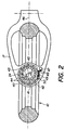
- the steering wheel 10 is articulated by means of the second bearing 24 which is mounted in a suitable circular recess formed in a plate 40 arranged to pivot around an axis 41 and held by an annular guide 42 secured to the suspension arm 17 of the vehicle.
- the outer element of the bearing 24 is made integral with the plate 40 by means of a fixing ring 43 and a set of bolts 44, and the inner element of the bearing 24 is coupled to the inner element 19 (not shown in this view) of the first bearing 22 of the wheel 10.
- the annular guide 42 is designed in such a way that the plate 40 can rotate around its pivot axis 41.
- a pivoting of the plate around its axis 41 has the effect of displacing the axis 45 of the second bearing on a arc of a circle centered on the axis 41 and schematically represented by the arrows A and B.
- This has the effect of shifting the median plane 46 of the wheel on one side or the other with respect to its normal position and allows, in particular at critical moments, to move the point of support of the wheel on the road with respect to the projection onto the latter of the center of gravity of the vehicle.
- the consequence is an enlargement of the lift surface of the vehicle and an increase in the stability of the latter due to a displacement of the stability limit.
- This effect is preferably controlled by an electric motor 47 capable of driving in one direction or the other a gear train 48 coupled to a worm 49 which engages a toothed sector 50 integral with the plate 40.
- This toothed sector can be constituted by the plate itself or by an attached element fixed to this plate.
- the electric motor 47 can be controlled directly by the pilot or controlled by an electronic circuit connected to a sensor designed to detect a critical inclination of the vehicle or the start of a skid, etc.
- control by electric motor and by screw could be replaced by any other suitable mechanical or electromechanical device.
- the pivoting of the plate 40 could be obtained by a jack or a hydraulic motor, an electromagnet with a plunger core, etc.
Landscapes
- Engineering & Computer Science (AREA)
- Mechanical Engineering (AREA)
- Steering-Linkage Mechanisms And Four-Wheel Steering (AREA)
- Axle Suspensions And Sidecars For Cycles (AREA)
- Steering Controls (AREA)
- Arrangement Or Mounting Of Propulsion Units For Vehicles (AREA)
- Vehicle Body Suspensions (AREA)
- Pharmaceuticals Containing Other Organic And Inorganic Compounds (AREA)
- Acyclic And Carbocyclic Compounds In Medicinal Compositions (AREA)
- Steering Devices For Bicycles And Motorcycles (AREA)
Claims (7)
- Motorisiertes oder gezogenes Fahrzeug zur Fortbewegung auf einer bestimmten Auflagefläche, wobei das Fahrzeug mindestens zwei Räder aufweist, wovon mindestens eines ein lenkbares Rad ist, und jedes dieser Räder aus einem inneren mit dem Grundaufbau des Fahrzeuges verbundenen Teil und einem zu dem inneren Teil konzentrischen peripheren Teil besteht, der so gestaltet ist, daß er sich um letzterer. dreht, und der innere Teil und der periphere Teil miteinander durch mindestens ein erstes ringförmiges Wälzlager verbunden sind, wobei dieses erste Wälzlager mindestens ein ringförmiges inneres Element hat, das mit dem inneren Teil des Rades fest verbunden ist und mindestens ein zu dem ringförmigen inneren Element konzentrisches, ringförmiges, peripheres Element, das mit dem peripheren Teil fest verbunden ist, und letzterer ein Kontaktorgan trägt, das der Beschaffenheit der Auflagefläche für das Fahrzeug entspricht, und außerdem der innere Teil des Rades in mindestens einer exzentrisch zum Rad liegenden Aufhängung mit dem Grundaufbau des Fahrzeuges verbunden ist, und weiterhin das lenkbare Rad mit dem Grundaufbau des Fahrzeuges durch mindestens ein zweites Wälzlager verbunden ist, das in einer zur Ebene des ersten Wälzlagers rechtwinklig liegenden Ebene angeordnet ist, und das ein mit dem ringförmigen inneren Element des ersten Wälzlagers fest verbundenes erstes inneres Element aufweist und ein zweites äußeres Element, das mit dem Grundaufbau des Fahrzeuges fest verbunden ist,
dadurch gekennzeichnet, daß das zweite Wälzlager (24) exzentrisch auf einer Platte (40) montiert ist, die um eine senkrecht zur Ebene der Platte liegende Achse (41) und parallel zum Bogen (45) des zweiten Wälzlagers (24) schwenkbar ist, und daß das Fahrzeug mit einer Einrichtung versehen ist, die dazu dient, die Platte (40) um ihre Achse (41) zu drehen. - Fahrzeug nach Anspruch 1,
dadurch gekennzeichnet, daß die Platte (40) in einer fest mit dem Aufhängungsarm (17) des Lenkrades (10) des Fahrzeuges verbundenen ringförmigen Führung (42) montiert ist. - Fahrzeug nach Anspruch 1,
dadurch gekennzeichnet, daß die zum Drehen der Platte (40) vorgesehene Einrichtung eine von einem Elektromotor (47) angetriebene Schraubenspindel (49) aufweist, wobei diese Schraubenspindel mit einem fest mit der Platte verbundenen gezahnten Sektor (50) im Eingriff steht. - Fahrzeug nach Anspruch 1,
dadurch gekennzeichnet, daß das zweite Wälzlager in einer in der Platte (40) angebrachten exzentrisch liegenden Aussparung eingebaut ist. - Fahrzeug nach Anspruch 1,
dadurch gekennzeichnet, daß das zweite Wälzlager (24) in der Platte (40) mittels eines zweiten äußeren Elementes befestigt ist. - Fahrzeug nach Anspruch 5,
dadurch gekennzeichnet, daß das zweite äußere Element des zweiten Wälzlagers (24) an der Platte (40) durch einen peripher an der in dieser Platte angebrachten exzentrischen Aussparung liegenden Befestigungsring fixiert ist. - Fahrzeug nach Anspruch 1,
dadurch gekennzeichnet, daß die zum Drehen der Platte (40) dienende Einrichtung mindestens eine mit einem Arbeitszylinder verbundene Anlenkstange aufweist.
Priority Applications (1)
| Application Number | Priority Date | Filing Date | Title |
|---|---|---|---|
| AT90901734T ATE93788T1 (de) | 1989-01-30 | 1990-01-29 | Fahrzeug mit verstellbarer lenkradgeometrie. |
Applications Claiming Priority (2)
| Application Number | Priority Date | Filing Date | Title |
|---|---|---|---|
| FR8901324 | 1989-01-30 | ||
| FR8901324A FR2642392B1 (fr) | 1989-01-30 | 1989-01-30 | Vehicule motorise ou tracte |
Publications (2)
| Publication Number | Publication Date |
|---|---|
| EP0414836A1 EP0414836A1 (de) | 1991-03-06 |
| EP0414836B1 true EP0414836B1 (de) | 1993-09-01 |
Family
ID=9378393
Family Applications (1)
| Application Number | Title | Priority Date | Filing Date |
|---|---|---|---|
| EP90901734A Expired - Lifetime EP0414836B1 (de) | 1989-01-30 | 1990-01-29 | Fahrzeug mit verstellbarer lenkradgeometrie |
Country Status (8)
| Country | Link |
|---|---|
| US (1) | US5121809A (de) |
| EP (1) | EP0414836B1 (de) |
| JP (1) | JPH04501990A (de) |
| AT (1) | ATE93788T1 (de) |
| CA (1) | CA2024705A1 (de) |
| DE (1) | DE69003058T2 (de) |
| FR (1) | FR2642392B1 (de) |
| WO (1) | WO1990008688A1 (de) |
Families Citing this family (9)
| Publication number | Priority date | Publication date | Assignee | Title |
|---|---|---|---|---|
| US5248019A (en) * | 1988-11-02 | 1993-09-28 | Sm Sbarro Mottas Engineering S.A. | Hub-less cycle or engine-driven vehicle |
| US5361864A (en) * | 1990-11-30 | 1994-11-08 | Yamaha Hatsudoki Kabushiki Kaisha | Front wheel suspension for motorcycle |
| FR2739162A1 (fr) * | 1995-09-27 | 1997-03-28 | Design Performance | Ensemble de freinage pour roue de vehicule, comportant un etrier et un disque de frein associe |
| US5992863A (en) * | 1998-03-18 | 1999-11-30 | 600 Racing, Inc. | Steering assembly having an adjustable alignment arrangement |
| US6161255A (en) * | 1998-08-06 | 2000-12-19 | Chmi | Pressure hinge device for glass door or panel |
| US7040640B2 (en) * | 2004-02-03 | 2006-05-09 | Honda Motor Company, Ltd. | Wheel assembly for a vehicle |
| US20080271938A1 (en) * | 2007-05-04 | 2008-11-06 | Benjamin Gulak | Motorized Cycle |
| DE102015105324A1 (de) * | 2015-04-08 | 2016-10-13 | Ujet Vehicles S.À.R.L. | Motorgetriebenes Fahrzeug, insbesondere Zweirad-Fahrzeug |
| US20200238754A1 (en) * | 2019-01-28 | 2020-07-30 | Andre Bradford | Hub-less rim for a wheel of a vehicle |
Family Cites Families (11)
| Publication number | Priority date | Publication date | Assignee | Title |
|---|---|---|---|---|
| FR890247A (fr) * | 1940-10-30 | 1944-02-02 | Cycle à moteur | |
| US4045096A (en) * | 1976-03-29 | 1977-08-30 | The Spokeless Wheel Patent Proceeds Partnership | Spokeless wheel and shroud therefor |
| US4526249A (en) * | 1983-05-25 | 1985-07-02 | Parker James G | Front suspension system for a motorcycle |
| FR2583703B1 (fr) * | 1985-06-25 | 1991-07-26 | Honda Motor Co Ltd | Motocycle a chassis perfectionne en deux parties dont un chassis inferieur comportant le systeme moteur |
| JPS6255204A (ja) * | 1985-09-03 | 1987-03-10 | Toyota Motor Corp | ト−イン調整装置 |
| US4723621A (en) * | 1985-10-30 | 1988-02-09 | Honda Giken Kogyo Kabushiki Kaisha | Motorcycle |
| JPS63162313A (ja) * | 1986-12-26 | 1988-07-05 | Honda Motor Co Ltd | 自動車のサスペンシヨン装置 |
| ATE76011T1 (de) * | 1987-02-09 | 1992-05-15 | Frank Jean Savard | Motorrad. |
| JPS6441383A (en) * | 1987-08-07 | 1989-02-13 | Canon Kk | Image pickup element fixing device |
| IT1233435B (it) * | 1987-12-23 | 1992-03-31 | Cagiva Motor | Sospensione per la ruota anteriore di motociclette e simili. |
| FR2633877B1 (fr) * | 1988-07-11 | 1994-03-25 | Mottas Dominique | Roue pour vehicule motorise ou tracte et vehicule equipe d'une telle roue |
-
1989
- 1989-01-30 FR FR8901324A patent/FR2642392B1/fr not_active Expired - Fee Related
-
1990
- 1990-01-29 US US07/582,975 patent/US5121809A/en not_active Expired - Fee Related
- 1990-01-29 AT AT90901734T patent/ATE93788T1/de not_active IP Right Cessation
- 1990-01-29 EP EP90901734A patent/EP0414836B1/de not_active Expired - Lifetime
- 1990-01-29 JP JP2501985A patent/JPH04501990A/ja active Pending
- 1990-01-29 CA CA002024705A patent/CA2024705A1/fr not_active Abandoned
- 1990-01-29 DE DE90901734T patent/DE69003058T2/de not_active Expired - Fee Related
- 1990-01-29 WO PCT/CH1990/000019 patent/WO1990008688A1/fr not_active Ceased
Also Published As
| Publication number | Publication date |
|---|---|
| US5121809A (en) | 1992-06-16 |
| FR2642392A1 (fr) | 1990-08-03 |
| FR2642392B1 (fr) | 1991-05-03 |
| CA2024705A1 (fr) | 1990-07-31 |
| DE69003058T2 (de) | 1994-02-17 |
| JPH04501990A (ja) | 1992-04-09 |
| DE69003058D1 (de) | 1993-10-07 |
| WO1990008688A1 (fr) | 1990-08-09 |
| ATE93788T1 (de) | 1993-09-15 |
| EP0414836A1 (de) | 1991-03-06 |
Similar Documents
| Publication | Publication Date | Title |
|---|---|---|
| EP0238768B1 (de) | Lager- und Aufhängungsvorrichtung, verbunden mit dem Vorderrad eines Motorfahrrades | |
| EP0236196B1 (de) | Aufhängungs- und Lenkungsvorrichtung für Motorrad | |
| EP0104108B1 (de) | Einarmschwinge für Antriebsräder | |
| EP0445841B1 (de) | Motorrad mit Vorderradantrieb und Lenkung mit Drehstab | |
| EP0414814B1 (de) | Rad eines motorfahrzeuges oder anhängers und ein mit diesem ausgerüstetes fahrzeug | |
| FR2636035A1 (fr) | Motocyclette a roue avant motrice | |
| EP0279135B1 (de) | Aufhängungs- und Schwenkvorrichtung von einem lenkbaren Rad eines Kraftfahrzeuges | |
| EP0025744B1 (de) | Vorderradaufhängung für Kraftfahrzeug | |
| EP1240072A1 (de) | Stabilisierungsmittel für zweirad-fahrzeug | |
| EP0409938B1 (de) | Fahrzeug mit regelbarer lenkradspur | |
| EP1885594B1 (de) | Strassenfahrzeug mit pendelfahrgastzelle | |
| EP4026763B1 (de) | Motorisiertes fahrzeug mit einem mechanismus mit anti-squat-wirkung | |
| EP0404880B1 (de) | Kraft- oder schleppfahrzeug mit nabenlosen rädern | |
| WO1990008688A1 (fr) | Vehicule avec roue directrice a geometrie variable | |
| FR2534213A1 (fr) | Tracteur ou vehicule similaire muni de roues motrices et directrices commandees par des fusees | |
| FR2692220A1 (fr) | Véhicule routier à disposition de roues perfectionnée. | |
| FR2962402A3 (fr) | Nouveau moyen de motorisation et ses utilisations | |
| FR2657563A1 (fr) | Essieu arriere de vehicule automobile comportant une traverse montee pivotante par rapport a la caisse et vehicule equipe d'un tel essieu. | |
| FR2711964A1 (fr) | Dispositif pour rendre motrice une roue de cyccle. | |
| FR2815598A1 (fr) | Vehicule a au moins deux roues | |
| FR2657580A1 (fr) | Dispositif de motorisation d'au moins une roue directrice d'un vehicule. | |
| BE394176A (de) | ||
| FR2594781A1 (fr) | Dispositif de suspension et de roulement associes a une roue avant de motocycle | |
| BE337159A (de) |
Legal Events
| Date | Code | Title | Description |
|---|---|---|---|
| PUAI | Public reference made under article 153(3) epc to a published international application that has entered the european phase |
Free format text: ORIGINAL CODE: 0009012 |
|
| 17P | Request for examination filed |
Effective date: 19900827 |
|
| AK | Designated contracting states |
Kind code of ref document: A1 Designated state(s): AT BE CH DE DK ES FR GB IT LI LU NL SE |
|
| RAP3 | Party data changed (applicant data changed or rights of an application transferred) |
Owner name: SBL SOCIETE BREVETS LICENCES S.A. |
|
| 17Q | First examination report despatched |
Effective date: 19930209 |
|
| GRAA | (expected) grant |
Free format text: ORIGINAL CODE: 0009210 |
|
| AK | Designated contracting states |
Kind code of ref document: B1 Designated state(s): AT BE CH DE DK ES FR GB IT LI LU NL SE |
|
| PG25 | Lapsed in a contracting state [announced via postgrant information from national office to epo] |
Ref country code: NL Effective date: 19930901 Ref country code: ES Free format text: THE PATENT HAS BEEN ANNULLED BY A DECISION OF A NATIONAL AUTHORITY Effective date: 19930901 Ref country code: DK Effective date: 19930901 Ref country code: AT Effective date: 19930901 |
|
| REF | Corresponds to: |
Ref document number: 93788 Country of ref document: AT Date of ref document: 19930915 Kind code of ref document: T |
|
| REF | Corresponds to: |
Ref document number: 69003058 Country of ref document: DE Date of ref document: 19931007 |
|
| ITF | It: translation for a ep patent filed | ||
| GBT | Gb: translation of ep patent filed (gb section 77(6)(a)/1977) |
Effective date: 19931006 |
|
| PGFP | Annual fee paid to national office [announced via postgrant information from national office to epo] |
Ref country code: SE Payment date: 19940105 Year of fee payment: 5 |
|
| PGFP | Annual fee paid to national office [announced via postgrant information from national office to epo] |
Ref country code: DE Payment date: 19940113 Year of fee payment: 5 |
|
| PGFP | Annual fee paid to national office [announced via postgrant information from national office to epo] |
Ref country code: GB Payment date: 19940119 Year of fee payment: 5 |
|
| PGFP | Annual fee paid to national office [announced via postgrant information from national office to epo] |
Ref country code: FR Payment date: 19940127 Year of fee payment: 5 |
|
| PG25 | Lapsed in a contracting state [announced via postgrant information from national office to epo] |
Ref country code: LU Free format text: LAPSE BECAUSE OF NON-PAYMENT OF DUE FEES Effective date: 19940131 Ref country code: BE Effective date: 19940131 |
|
| PGFP | Annual fee paid to national office [announced via postgrant information from national office to epo] |
Ref country code: CH Payment date: 19940209 Year of fee payment: 5 |
|
| NLV1 | Nl: lapsed or annulled due to failure to fulfill the requirements of art. 29p and 29m of the patents act | ||
| PLBE | No opposition filed within time limit |
Free format text: ORIGINAL CODE: 0009261 |
|
| STAA | Information on the status of an ep patent application or granted ep patent |
Free format text: STATUS: NO OPPOSITION FILED WITHIN TIME LIMIT |
|
| BERE | Be: lapsed |
Owner name: SOC. BREVETS LICENCES S.A. SBL Effective date: 19940131 |
|
| 26N | No opposition filed | ||
| PG25 | Lapsed in a contracting state [announced via postgrant information from national office to epo] |
Ref country code: GB Effective date: 19950129 |
|
| PG25 | Lapsed in a contracting state [announced via postgrant information from national office to epo] |
Ref country code: SE Effective date: 19950130 |
|
| EAL | Se: european patent in force in sweden |
Ref document number: 90901734.5 |
|
| PG25 | Lapsed in a contracting state [announced via postgrant information from national office to epo] |
Ref country code: LI Effective date: 19950131 Ref country code: CH Effective date: 19950131 |
|
| GBPC | Gb: european patent ceased through non-payment of renewal fee |
Effective date: 19950129 |
|
| PG25 | Lapsed in a contracting state [announced via postgrant information from national office to epo] |
Ref country code: FR Effective date: 19950929 |
|
| REG | Reference to a national code |
Ref country code: CH Ref legal event code: PL |
|
| PG25 | Lapsed in a contracting state [announced via postgrant information from national office to epo] |
Ref country code: DE Effective date: 19951003 |
|
| EUG | Se: european patent has lapsed |
Ref document number: 90901734.5 |
|
| REG | Reference to a national code |
Ref country code: FR Ref legal event code: ST |
|
| PG25 | Lapsed in a contracting state [announced via postgrant information from national office to epo] |
Ref country code: IT Free format text: LAPSE BECAUSE OF NON-PAYMENT OF DUE FEES;WARNING: LAPSES OF ITALIAN PATENTS WITH EFFECTIVE DATE BEFORE 2007 MAY HAVE OCCURRED AT ANY TIME BEFORE 2007. THE CORRECT EFFECTIVE DATE MAY BE DIFFERENT FROM THE ONE RECORDED. Effective date: 20050129 |