EP0414860B1 - Schraubkappe aus kunststoffmaterial - Google Patents
Schraubkappe aus kunststoffmaterial Download PDFInfo
- Publication number
- EP0414860B1 EP0414860B1 EP90903756A EP90903756A EP0414860B1 EP 0414860 B1 EP0414860 B1 EP 0414860B1 EP 90903756 A EP90903756 A EP 90903756A EP 90903756 A EP90903756 A EP 90903756A EP 0414860 B1 EP0414860 B1 EP 0414860B1
- Authority
- EP
- European Patent Office
- Prior art keywords
- cap
- braking element
- screw cap
- cap according
- screw
- Prior art date
- Legal status (The legal status is an assumption and is not a legal conclusion. Google has not performed a legal analysis and makes no representation as to the accuracy of the status listed.)
- Expired - Lifetime
Links
Images


Classifications
-
- B—PERFORMING OPERATIONS; TRANSPORTING
- B65—CONVEYING; PACKING; STORING; HANDLING THIN OR FILAMENTARY MATERIAL
- B65D—CONTAINERS FOR STORAGE OR TRANSPORT OF ARTICLES OR MATERIALS, e.g. BAGS, BARRELS, BOTTLES, BOXES, CANS, CARTONS, CRATES, DRUMS, JARS, TANKS, HOPPERS, FORWARDING CONTAINERS; ACCESSORIES, CLOSURES, OR FITTINGS THEREFOR; PACKAGING ELEMENTS; PACKAGES
- B65D41/00—Caps, e.g. crown caps or crown seals, i.e. members having parts arranged for engagement with the external periphery of a neck or wall defining a pouring opening or discharge aperture; Protective cap-like covers for closure members, e.g. decorative covers of metal foil or paper
- B65D41/02—Caps or cap-like covers without lines of weakness, tearing strips, tags, or like opening or removal devices
- B65D41/04—Threaded or like caps or cap-like covers secured by rotation
-
- B—PERFORMING OPERATIONS; TRANSPORTING
- B65—CONVEYING; PACKING; STORING; HANDLING THIN OR FILAMENTARY MATERIAL
- B65D—CONTAINERS FOR STORAGE OR TRANSPORT OF ARTICLES OR MATERIALS, e.g. BAGS, BARRELS, BOTTLES, BOXES, CANS, CARTONS, CRATES, DRUMS, JARS, TANKS, HOPPERS, FORWARDING CONTAINERS; ACCESSORIES, CLOSURES, OR FITTINGS THEREFOR; PACKAGING ELEMENTS; PACKAGES
- B65D41/00—Caps, e.g. crown caps or crown seals, i.e. members having parts arranged for engagement with the external periphery of a neck or wall defining a pouring opening or discharge aperture; Protective cap-like covers for closure members, e.g. decorative covers of metal foil or paper
- B65D41/02—Caps or cap-like covers without lines of weakness, tearing strips, tags, or like opening or removal devices
- B65D41/04—Threaded or like caps or cap-like covers secured by rotation
- B65D41/0471—Threaded or like caps or cap-like covers secured by rotation with means for positioning the cap on the container, or for limiting the movement of the cap, or for preventing accidental loosening of the cap
Definitions
- the invention relates to a screw cap made of plastic material according to the preamble of claim 1.
- a screw cap is previously known from FR-A-2 569 661.
- Screw caps of this type are produced in very large quantities by injection molding and are used to close containers of the most varied types. Screw caps made of plastic material have become established, particularly in the area of soft drinks. The screw caps are automatically screwed onto the filled bottles in a fast-running filling line.
- a problem with known screw caps is that they have to be screwed on with a certain torque in order to ensure a tight seal.
- the screwing motion is usually limited by the fact that the bottle mouth is on the bottom of the cap.
- the cap will be unscrewed with too much torque, so that it can then hardly be unscrewed by hand.
- the threads can also be overtightened, since the bottle mouths have large tolerance fluctuations, particularly in the case of glass bottles.
- the braking element arranged in the area of the screw line of the external container thread causes the screwing-on process to be blocked without the container opening running onto the cap base with the full torque.
- the screwing forces are converted into a radial force component, since the external thread tries to overcome the braking element and thus to displace it radially outwards.
- the stoppage of the screw cap can be brought about with a delay. It is particularly advantageous if the braking element has a run-up flank that runs approximately parallel to the central axis of the cap. In addition, the run-up flank can be inclined to a plane running through the central axis of the cap. The run-up flank is then designed like a ramp on which the external thread runs with increasing radial tension.
- the braking element can be integrated in the thread of the internal thread, or it can be formed separately from the thread of the internal thread.
- the braking element can also have a wall section designed as a thread flank for the internal thread. In this way, the braking element is given an additional function. This function can be expanded if the screw cap has one or more support ribs close to the cap base for holding an inserted sealing washer, and if the braking element has a wall section which runs in the plane of the support ribs. As a result, part of the sealing washer rests on the brake element.
- the multiple functions of the braking element mentioned can be achieved in a particularly simple manner in that it has the shape of a wedge in plan view that extends over one Sector extends from at least 90 °.
- the run-up flank is arranged on the narrow side of the wedge, which must have a certain minimum width so that the thread start of the external thread always runs onto the braking element even in the event of tolerance fluctuations.
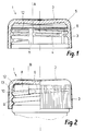
- a screw cap 1 is shown in FIG. 1, which essentially consists of a cap base 2 and an adjoining, approximately cylindrical cap wall 3. in the Transition area 5 between cap base 2 and cap wall 3, the screw cap is rounded. On the inside of the cap wall 3, the internal thread 4 is arranged, which has approximately 11 ⁇ 2 threads. These are interrupted by ventilation slots 11, which bring about a rapid reduction in pressure when the cap is unscrewed if there is excess pressure in the container.
- Support ribs 13 are arranged on the cap wall 3 close to the cap base 2 or at the transition region 5. These support ribs serve to hold a sealing washer 12 made of elastic material. As can be seen from FIG. 2, this sealing washer is pushed upwards when the cap is screwed on, whereby it lies sealingly around the mouth region.
- the braking element 15 At the threaded end 7 of the internal thread 4 there is a braking element 15 which is somewhat less deep than the flanks of the internal thread 4. As FIG. 4 shows, the braking element is designed as an elongated wedge in plan view. it is not connected to the threaded end 7, but begins immediately after a vent slot 11. The braking element extends over the sector from A to B over a little more than 180 °.
- the braking element has a run-up flank 16 which is inclined at an angle alpha to a plane running through the central axis of the cap, as can be seen from FIG. 3.
- the run-up flank runs parallel to the central axis, so that a radial force component in the direction of the arrow X is formed when the thread start 10 runs up.
- the braking element has a wall section 14 which is inclined at the pitch angle of the internal thread 4 and which practically fulfills the function of a thread flank.
- the braking element also has a wall section 15, which in the level of the support ribs 13 lies.
- the wall section 15 forms a continuation of the support ribs 13 on which the sealing washer 12 rests.
- the support ribs 13 are interrupted at the ventilation slots 11 in order to ensure optimum pressure reduction. but it would also be conceivable to arrange a single, contiguous support rib.
- the wedge-shaped brake element 6 shown in FIG. 4 obviously has a multiple function in that it serves as a stop for the external thread, as a thread flank and as a support shoulder for the sealing disk. This configuration is also particularly advantageous in terms of injection molding and tooling and can be easily removed from the mold.
- the braking element 6 does not necessarily have to have the wedge shape shown in the exemplary embodiment.
- the wall section 15 can easily be omitted or take a different relative position.
- the configuration of the braking element must always be such that it is always in the area of the screw line for the external thread.
- Figures 5 and 6 show alternative configurations of brake elements.
- the radial depth can be approximately the same as in the exemplary embodiment according to FIGS. 1 to 4.
- the braking element 6 is integrally connected to the threaded end 7 of the internal thread and extends like a flag in the helix of the external thread.
- the thread start 10 of the external thread also runs frontally on the braking element 6.
- the braking element 6 is U-shaped and is arranged completely separately. The lower leg could theoretically also form the continuation of the internal thread.
- the thread start 10 of the external thread does not run frontally here, but on the two flanks on the braking element.
- the braking element 6 is designed as a rib, which can extend over the entire circumference of the cap wall 3 or only over a specific sector.
- the underside 17 of the rib runs onto the beginning of the external thread 9.
- the underside 17 exerts an axial braking force.
- the rib could e.g. also serve as reinforcement of the transition area from the cap base 2 to the cap wall 3.
- FIGS. 8 and 9 An alternative embodiment of a screw cap according to the invention is shown in FIGS. 8 and 9.
- the screw cap 1 has an olive-shaped inner seal 21 on the cap base 2, which is pressed into the bottle mouth when screwed on.
- a guarantee tape 18 is arranged over tear-off webs, which is provided on the inside with at least one retaining element.
- a circumferential bead 19 is provided, under which the retaining element 20 engages when the cap is screwed on for the first time.
- the guarantee band is completely or partially separated from the lower edge of the cap, so that a first opening is indicated.
- the retaining elements having different shapes, e.g. Squats, tongues, beads, etc. may have.
- the braking element 6 is now particularly advantageously arranged in such a way that its braking action begins when the cap is screwed on for the first time immediately after the retaining element 20 engages under the bead 19.
- the braking element 6 could also be arranged in such a way that the braking effect starts before the retaining element engages and that when the braking process is ended, ie when the screw cap is at a standstill, the engaging position is just reached.
- the braking element consists of a rib or a thickening in the transition region 5 of the cap.
- the rib extends over an angle beta of approximately 75 °.
- the inner radius r of the rib is less than half the diameter d of the external thread 9.
- the thread start 10 of the external thread thus runs on the run-up flank 16, presses the rib 6 radially outward and brings about standstill due to the increased friction after a certain arc length the screw cap.
Landscapes
- Engineering & Computer Science (AREA)
- Mechanical Engineering (AREA)
- Closures For Containers (AREA)
Description
- Die Erfindung betrifft eine Schraubkappe aus Kunststoffmaterial gemäss dem Oberbegriff von Anspruch 1. Eine derartige Schraubkappe ist aus FR-A-2 569 661 vorbekannt. Derartige Schraubkappen werden im Spritzgiessverfahren in sehr grossen Stückzahlen hergestellt und dienen zum Verschliessen von Behältern unterschiedlichster Art. Vor allem im Bereich der Erfrischungsgetränke haben sich Schraubkappen aus Kunststoffmaterial durchgesetzt. Dabei werden die Schraubkappen in rasch laufenden Abfüllstrasse automatisch auf die gefüllten Flaschen aufgeschraubt.
- Ein Problem bei bekannten Schraubkappen besteht darin, dass sie mit einem bestimmten Drehmoment aufgeschraubt werden müssen, um einen dichten Verschluss zu gewährleisten. Die Aufschraubbewegung wird dabei in der Regel dadurch begrenzt, dass die Flaschenmündung am Kappenboden ansteht. Dabei besteht jedoch die Gefahr, dass die Kappe mit einem zu grossen Drehmoment aufgeschraubt wird, so dass sie anschliessend von Hand fast nicht mehr abgeschraubt werden kann. Auch ein Ueberdrehen der Gewindegänge kann in bestimmten Fällen eintreten, da die Flaschenmündungen vor allem bei Glasflaschen grosse Toleranzschwankungen aufweisen.
- Es ist daher eine Aufgabe der Erfindung, die Schraubkappen der eingangs genannten Art so auszubilden, dass die Aufschraubbewegung nicht mehr oder nicht mehr ausschliesslich durch den Kappenboden begrenzt wird, und dass ein Aufschrauben der Kappe auf die Behältermündung mit einem zu grossen Drehmoment verhindert wird. Diese Aufgabe wird erfindungsgemäss mit einer Schraubkappe gelöst, welche die Merkmale im Anspruch 1 aufweist.
- Das im Bereich der Schraubenlinie des Behälter-Aussengewindes angeordnete Bremselement bewirkt eine Blockierung des Aufschraubvorgangs, ohne dass dabei die Behältermündung mit dem vollen Drehmoment am Kappenboden aufläuft. Beim Auflaufen des Aussengewindes auf das Bremselement werden die Aufschraubkräfte in eine radiale Kraftkomponente umgewandelt, da das Aussengewinde bestrebt ist, das Bremselement zu überwinden und damit radial nach aussen zu verdrängen.
- Je nach der Ausgestaltung des Bremselements und nach den elastizitätseigenschaften des Materials kann der Stillstand der Schraubkappe mit einer Verzögerung herbeigeführt werden. Dabei ist es besonders vorteilhaft, wenn das Bremselement eine Auflaufflanke aufweist, die etwa parallel zur Mittelachse der Kappe verläuft. Ausserdem kann die Auflaufflanke zu einer durch die Mittelachse der Kappe verlaufenden ebene geneigt sein. Die Auflaufflanke ist dann wie eine Rampe ausgebildet, auf der das Aussengewinde mit zunehmender radialer Spannung aufläuft.
- Das Bremselement kann in den Gewindegang des Innengewindes integriert sein, oder es kann vom Gewindegang des Innengewindes getrennt ausgebildet sein. Das Bremselement kann auch einen als Gewindeflanke für das Innengewinde ausgebildeten Wandabschnitt aufweisen. Auf diese Weise erhält das Bremselement noch eine zusätzliche Funktion. Diese Funktion kann noch erweitert werden, wenn die Schraubkappe nahe am Kappenboden eine oder mehrere Stützrippen zum Festhalten einer eingelegten Dichtungsscheibe aufweist, und wenn das Bremselement einen Wandabschnitt aufweist, der in der ebene der Stützrippen verläuft. Dadurch liegt ein Teil der Dichtungsscheibe auf dem Bremselement auf.
- Die erwähnten Mehrfachfunktionen des Bremselements können besonders einfach dadurch erreicht werden, dass es in der Draufsicht die Form eines Keils aufweist, der sich über einen Sektor von wenigstens 90° erstreckt. An der Schmalseite des Keils ist dabei die Auflaufflanke angeordnet, die eine bestimmte Minimalbreite haben muss, damit auch bei Toleranzschwankungen der Gewindeanfang des Aussengewindes immer auf das Bremselement aufläuft.
- Ein Ausführungsbeispiel der Erfindung ist in den Zeichnungen dargestellt und wird nachstehend genauer beschrieben. Es zeigen:
- Figur 1
- einen querschnitt durch eine erfindungsgemässe Schraubkappe,
- Figur 2
- einen querschnitt durch die auf eine Behältermündung aufgeschraubte Schraubkappe gemäss Figur 1,
- Figur 3
- einen Teilquerschnitt durch die Verschlussanordnung gemäss Figur 2,
- Figur 4
- eine Abwicklung der Kappeninnenwand in etwas verkleinertem Massstab,
- Figuren 5 und 6
- Draufsichten auf abgewandelte Ausführungsbeispiele von Bremselementen,
- Figur 7
- ein als umlaufende Rippe ausgebildetes Bremselement,
- Figur 8
- ein abgewandeltes Ausführungsbeispiel an einer Kappe mit einem abreissbaren Garantieband, und
- Figur 9
- einen Schnitt durch die ebene I-I gemäss Figur 8.
- In Figur 1 ist eine Schraubkappe 1 dargestellt, die im wesentlichen aus einem Kappenboden 2 und einer sich daran anschliessenden, etwa zylindrischen Kappenwand 3 besteht. Im Uebergangsbereich 5 zwischen Kappenboden 2 und Kappenwand 3 ist die Schraubkappe abgerundet. Auf der Innenseite der Kappenwand 3 ist das Innengewinde 4 angeordnet, das ca. 1½ Gewindegänge aufweist. Diese sind durch Entlüftungsschlitze 11 unterbrochen, die beim Abschrauben der Kappe einen raschen Druckabbau bewirken, wenn im Behälter ein Ueberdruck herrscht.
- Nahe am Kappenboden 2 bzw. am Uebergangsbereich 5 sind an der Kappenwand 3 Stützrippen 13 angeordnet. Diese Stützrippen dienen dazu, eine Dichtungsscheibe 12 aus elastischem Material festzuhalten. Wie aus Figur 2 ersichtlich ist, wird diese Dichtungsscheibe bei aufgeschraubter Kappe nach oben geschoben, wobei sie sich dichtend um den Mündungsbereich legt.
- Am Gewindeende 7 des Innengewindes 4 ist ein Bremselement 15 angeordnet, das etwas weniger tief ausgebildet ist als die Flanken des Innengewindes 4. Wie Figur 4 zeigt, ist das Bremselement in der Draufsicht als langgestreckter Keil ausgebildet. es ist nicht mit dem Gewindeende 7 verbunden, sondern beginnt unmittelbar nach einem Entlüftungsschlitz 11. Das Bremselement erstreckt sich über den Sektor von A bis B über etwas mehr als 180°.
- Das Bremselement hat eine Auflaufflanke 16, die zu einer durch die Mittelachse der Kappe verlaufenden ebene in einem Winkel Alpha geneigt ist, wie aus Figur 3 hervorgeht. Die Auflaufflanke verläuft im übrigen jedoch parallel zur Mittelachse, so dass beim Auflaufen des Gewindeanfangs 10 eine radiale Kraftkomponente in Pfeilrichtung X gebildet wird.
- Das Bremselement weist einen Wandabschnitt 14 auf, der im Steigungswinkel des Innengewindes 4 geneigt ist und der praktisch die Funktion einer Gewindeflanke erfüllt. Anderseits hat das Bremselement auch noch einen Wandabschnitt 15, der in der ebene der Stützrippen 13 liegt. Dadurch bildet der Wandabschnitt 15 eine Fortsetzung der Stützrippen 13, auf denen die Dichtungsscheibe 12 aufliegt. Die Stützrippen 13 sind an den Entlüftungsschlitzen 11 unterbrochen, um einen optimalen Druckabbau zu gewährleisten. es wäre aber auch denkbar, eine einzige, zusammenhängende Stützrippe anzuordnen.
- Das in Figur 4 dargestellte keilförmige Bremselement 6 hat ersichtlicherweise eine Mehrfachfunktion, indem es als Anschlag für das Aussengewinde, als Gewindeflanke und als Stützschulter für die Dichtungsscheibe dient. Diese Konfiguration ist auch spritzgiesstechnisch und werkzeugtechnisch besonders vorteilhaft und lässt sich leicht entformen.
- Ersichtlicherweise muss das Bremselement 6 nicht zwingend die im Ausführungsbeispiel gezeigte Keilform aufweisen. Bei Verschlusskappen mit alternativen Dichtungssystemen kann ohne weiteres auch der Wandabschnitt 15 wegfallen bzw. eine andere Relativlage einnehmen. Die Konfiguration des Bremselements muss in jedem Fall so sein, dass es immer im Bereich der Schraubenlinie für das Aussengewinde liegt.
- Die Figuren 5 und 6 zeigen alternative Konfigurationen von Bremselementen. Die radiale Tiefe kann dabei etwa gleich sein wie beim Ausführungsbeispiel gemäss den Figuren 1 bis 4.
- Gemäss Figur 5 ist das Bremselement 6 einstückig mit dem Gewindeende 7 des Innengewindes verbunden und erstreckt sich wie eine Fahne in die Schraubenlinie des Aussengewindes. Der Gewindeanfang 10 des Aussengewindes läuft ebenfalls frontal auf dem Bremselement 6 auf. Beim Ausführungsbeispiel gemäss Figur 6 ist das Bremselement 6 U-förmig ausgebildet und völlig separat angeordnet. Der untere Schenkel könnte aber theoretisch auch die Fortsetzung des Innengewindes bilden. Der Gewindeanfang 10 des Aussengewindes läuft hier nicht frontal, sondern an den beiden Flanken am Bremselement auf.
- Beim Ausführungsbeispiel gemäss Figur 7 ist das Bremselement 6 als Rippe ausgebildet, die sich über den gesamten Umfang der Kappenwand 3 oder auch nur über einen bestimmten Sektor erstrecken kann. Beim Aufschrauben läuft die Unterseite 17 der Rippe auf dem Anfang des Aussengewindes 9 auf. Im Gegensatz zur vorher beschriebenen, radial wirkenden Auflaufflanke 16 übt die Unterseite 17 eine axiale Bremskraft aus. Die Rippe könnte z.B. auch noch als Verstärkung des Uebergangsbereiches vom Kappenboden 2 zur Kappenwand 3 dienen.
- Ein alternatives Ausführungsbeispiel einer erfindungsgemässen Schraubkappe ist in den Figuren 8 und 9 dargestellt. Anstelle einer eingelegten Dichtungsscheibe verfügt die Schraubkappe 1 am Kappenboden 2 über eine olivenförmige Innendichtung 21, die beim Aufschrauben in die Flaschenmündung hineingepresst wird. Am unteren Rand der Schraubkappe ist über abreissbare Stege ein Garantieband 18 angeordnet, das auf der Innenseite mit wenigstens einem Rückhalteelement versehen ist. An der Behältermündung 8 ist ein umlaufender Wulst 19 vorgesehen, unter dem das Rückhalteelement 20 beim erstmaligen Aufschrauben der Kappe einrastet. Beim erstmaligen Abschrauben derKappe wird das Garantieband ganz oder teilweise vom unteren Kappenrand abgetrennt, so dass ein erstmaliges Oeffnen angezeigt wird. Derartige Garantiebänder sind dem Fachmann bereits bekannt, wobei die Rückhalteelemente verschiedene Formen, wie z.B. Hocken, Zungen, Wulste usw. haben können.
- Das Bremselement 6 ist nun besonders vorteilhaft so angeordnet, dass seine Bremswirkung beim erstmaligen Aufschrauben der Kappe unmittelbar nach dem einrasten des Rückhalteelementes 20 unter dem Wulst 19 einsetzt. Je nach der Beschaffenheit der Rückhalteelemente kann es nämlich für die Funktion des Garantiebandes bedeutsam sein, dass das Garantieband eine bestimmte Relativlage zum Wulst 19 nicht überschreitet. Das Bremselement 6 könnte aber auch derart angeordnet werden, dass die Bremswirkung bereits vor dem einrasten des Rückhalteelements einsetzt und dass beim Beenden des Bremsvorgangs, d.h. beim Stillstand der Schraubkappe, die einrastposition gerade erreicht wird.
- Beim Ausführungsbeispiel gemäss den Figuren 8 und 9 besteht das Bremselement aus einer Rippe bzw. aus einer Verdickung im Uebergangsbereich 5 der Kappe. Die Rippe erstreckt sich über einen Winkel Beta von ca. 75°. Der innere Radius r der Rippe ist kleiner als die Hälfte des Durchmessers d des Aussengewindes 9. Damit läuft der Gewindeanfang 10 des Aussengewindes auf der Auflaufflanke 16 auf, drückt die Rippe 6 radial nach aussen und bewirkt durch die erhöhte Reibung nach einer bestimmten Bogenlänge den Stillstand der Schraubkappe.
- Selbstverständlich könnte auch die Schraubkappe gemäss den Figuren 1 bis 3 mit einem Garantieband gemäss Figur 8 versehen werden.
Claims (11)
- Schraubkappe (1) aus Kunststoffmaterial mit einem Kappenboden (2) und einer sich daran anschliessenden, etwa zylindrischen Kappenwand (3) mit Innengewinde (4), zum Verschliessen einer Behältermündung (8) mit Aussengewinde (9), dadurch gekennzeichnet, dass an dem dem Kappenboden (2) zugewandten Ende (7) des Innengewindes (4) ein Bremselement (6) an der Kappenwand (3) angeordnet ist, das wenigstens teilweise im Bereich der Schraubenlinie für das Aussengewinde (9) liegt.
- Schraubkappe nach Anspruch 1, dadurch gekennzeichnet, dass das Bremselement (6) eine Auflaufflanke (16) aufweist, die etwa parallel zur Mittelachse der Kappe verläuft.
- Schraubkappe nach Anspruch 1 oder 2, dadurch gekennzeichnet, dass das Bremselement (6) eine Auflaufflanke (16) aufweist, welche zu einer durch die Mittelachse der Kappe verlaufenden Ebene geneigt ist.
- Schraubkappe nach einem der Ansprüche 1 bis 3, dadurch gekennzeichnet, dass das Bremselement (6) in den Gewindegang des Innengewindes (4) integriert ist.
- Schraubkappe nach einem der Ansprüche 1 bis 3, dadurch gekennzeichnet, dass das Bremselement (6) vom Gewindegang des Innengewindes getrennt ausgebildet ist.
- Schraubkappe nach einem der Ansprüche 1 bis 5, dadurch gekennzeichnet, dass das Bremselement einen als Gewindeflanke für das Innengewinde ausgebildeten Wandabschnitt (14) aufweist.
- Schraubkappe nach einem der Ansprüche 1 bis 6, dadurch gekennzeichnet, dass sie nahe am Kappenboden (2) eine oder mehrere Stützrippen (13) zum Festhalten einer eingelegten Dichtungsscheibe (12) aufweist, und dass das Bremselement (6) einen Wandabschnitt (15) aufweist, der in der Ebene der Stützrippen (13) verläuft.
- Schraubkappe nach Anspruch 6 oder 7, dadurch gekennzeichnet, dass das Bremselement (6) in der Draufsicht die Form eines Keils aufweist, der sich über einen Sektor von wenigstens 90° erstreckt.
- Schraubkappe nach Anspruch 1, dadurch gekennzeichnet, dass das Bremselement (6) eine Rippe ist, die sich über wenigstens einen Sektor des Umfangsbereichs erstreckt und die so angeordnet ist, dass sie beim Aufschrauben der Kappe auf dem Gewindeanfang des Aussengewindes (9) aufläuft.
- Schraubkappe nach Anspruch 9, dadurch gekennzeichnet, dass sich die Rippe über den gesamten Umfangsbereich der Kappenwand (3) erstreckt.
- Schraubkappe nach einem der Ansprüche 1 bis 10, dadurch gekennzeichnet, dass sie an ihrem unteren Rand ein Garantieband (18) aufweist, das auf der Innenseite mit wenigstens einem Rückhalteelement versehen ist, mit dem bei aufgeschraubter Kappe ein ringförmiger Vorsprung an der Behältermündung untergreifbar ist, wobei das Bremselement derart angeordnet ist, dass die Bremswirkung unmittelbar nach dem Einrasten des Rückhalteelements einsetzt.
Applications Claiming Priority (3)
| Application Number | Priority Date | Filing Date | Title |
|---|---|---|---|
| ES19898900826U ES1009616Y (es) | 1989-03-14 | 1989-03-14 | Dispositivo de tope para roscas de tapones. |
| CH184189 | 1989-05-17 | ||
| CH1841/89 | 1989-05-17 |
Publications (2)
| Publication Number | Publication Date |
|---|---|
| EP0414860A1 EP0414860A1 (de) | 1991-03-06 |
| EP0414860B1 true EP0414860B1 (de) | 1993-09-01 |
Family
ID=25688811
Family Applications (1)
| Application Number | Title | Priority Date | Filing Date |
|---|---|---|---|
| EP90903756A Expired - Lifetime EP0414860B1 (de) | 1989-03-14 | 1990-03-09 | Schraubkappe aus kunststoffmaterial |
Country Status (8)
| Country | Link |
|---|---|
| EP (1) | EP0414860B1 (de) |
| KR (1) | KR100197824B1 (de) |
| AT (1) | ATE93803T1 (de) |
| BR (1) | BR9005774A (de) |
| CA (1) | CA2027537A1 (de) |
| ES (1) | ES2043360T3 (de) |
| FI (1) | FI905643A7 (de) |
| WO (1) | WO1990010581A2 (de) |
Families Citing this family (5)
| Publication number | Priority date | Publication date | Assignee | Title |
|---|---|---|---|---|
| DE4126418C2 (de) * | 1991-08-09 | 2002-08-29 | Michael Hertrampf | Schraubkappe zum Verschließen einer Flasche oder dergleichen |
| DE59408916D1 (de) * | 1994-01-05 | 1999-12-16 | Ewit Ag Zug | Maschinell aufsetzbarer Kunststoff-Schraubverschluss |
| IL112387A (en) * | 1994-02-01 | 1997-07-13 | Crown Cork Ag | Screwable closure cap with security against over- tightening |
| GB2321053A (en) * | 1997-01-08 | 1998-07-15 | Massmould Holdings | Screw cap with liner |
| EP1097877A1 (de) * | 1999-11-08 | 2001-05-09 | Crown Cork & Seal Technologies Corporation | Verschlusskappe |
Family Cites Families (4)
| Publication number | Priority date | Publication date | Assignee | Title |
|---|---|---|---|---|
| US3435978A (en) * | 1967-01-23 | 1969-04-01 | John C Wittwer | Bottle cap with interlocking threads |
| US4464316A (en) * | 1982-07-23 | 1984-08-07 | Baxter Travenol Laboratories, Inc. | Non-refillable humidifier container |
| FR2569661B1 (fr) * | 1984-09-03 | 1986-09-19 | Mayet Ets | Dispositif de bouchage a orientation definie |
| US4741447A (en) * | 1987-04-27 | 1988-05-03 | American National Can Company | Linerless cap closure |
-
1990
- 1990-03-09 WO PCT/CH1990/000060 patent/WO1990010581A2/de not_active Ceased
- 1990-03-09 AT AT90903756T patent/ATE93803T1/de not_active IP Right Cessation
- 1990-03-09 FI FI905643A patent/FI905643A7/fi not_active Application Discontinuation
- 1990-03-09 ES ES90903756T patent/ES2043360T3/es not_active Expired - Lifetime
- 1990-03-09 BR BR909005774A patent/BR9005774A/pt not_active IP Right Cessation
- 1990-03-09 EP EP90903756A patent/EP0414860B1/de not_active Expired - Lifetime
- 1990-03-09 CA CA002027537A patent/CA2027537A1/en not_active Abandoned
- 1990-03-09 KR KR1019900702457A patent/KR100197824B1/ko not_active Expired - Fee Related
Also Published As
| Publication number | Publication date |
|---|---|
| WO1990010581A2 (de) | 1990-09-20 |
| FI905643A0 (fi) | 1990-11-14 |
| ES2043360T3 (es) | 1993-12-16 |
| CA2027537A1 (en) | 1990-09-15 |
| KR100197824B1 (ko) | 1999-06-15 |
| ATE93803T1 (de) | 1993-09-15 |
| BR9005774A (pt) | 1991-08-06 |
| WO1990010581A3 (de) | 1990-11-29 |
| KR920700152A (ko) | 1992-02-19 |
| FI905643A7 (fi) | 1990-11-14 |
| EP0414860A1 (de) | 1991-03-06 |
Similar Documents
| Publication | Publication Date | Title |
|---|---|---|
| DE2529340C3 (de) | Behälter mit einer Schraubkappe und Verfahren zum Aufsetzen der Schraubkappe | |
| EP0690812B1 (de) | Schraubbare verschlusskappe mit überdrehsicherung | |
| DE60206794T2 (de) | Benutzerfreundliche flasche und schraubverschluss | |
| DE69431606T2 (de) | Hochdruck-Sicherheitsverschluss-Einheit an Behältern für kohlensäurehaltige Getränke | |
| EP0154603B1 (de) | Verschlusskappe aus Kunststoffmaterial | |
| EP0308753B1 (de) | Flaschenverschluss, insbesondere für Sektflaschen mit Schraubgewinde-Mündung | |
| EP0076778A1 (de) | Verschlusskappe aus Kunststoffmaterial | |
| EP0661218A1 (de) | Verschlusskappe aus Kunststoffmaterial mit frühzeitig lüftender Innendichtung | |
| DE1804549A1 (de) | Sicherheitsverschluss fuer Behaelter | |
| DE2421292B2 (de) | Kindersicherer verschluss fuer einen behaelter | |
| DE68917938T4 (de) | Deckel ohne innenbekleidung für kohlensäurehaltige getränkebehälter. | |
| DE3139526A1 (de) | Verschlusskappe aus kunststoffmaterial | |
| DE1804099B2 (de) | Behälter mit Schraubverschlußkappe | |
| DE2638351C3 (de) | Garantieverschluß für Flaschen | |
| DE2704454C2 (de) | Behälterverschluß | |
| WO1990010581A2 (de) | Schraubkappe aus kunststoffmaterial | |
| EP0904237B1 (de) | Behälterverschluss und behältermündung | |
| DE2510257A1 (de) | M verschlusskombination fuer flaschen und behaelter | |
| WO1991011369A1 (de) | Schraubkappe mit garantieband | |
| AT405815B (de) | Anschlageinrichtung für eine flaschenverschluss-kappe | |
| EP0343102A2 (de) | Verschlusskappe aus Kunststoffmaterial | |
| CH597052A5 (en) | Plastics sealing disc for screw-on container closure | |
| EP0060218A2 (de) | Drehverschluss-anordnung zum Verschliessen von unter Innendruck stehenden Behältern | |
| DE2856433A1 (de) | Verschluss fuer behaelter | |
| DE2601771A1 (de) | Schraubverschluss fuer behaelter |
Legal Events
| Date | Code | Title | Description |
|---|---|---|---|
| PUAI | Public reference made under article 153(3) epc to a published international application that has entered the european phase |
Free format text: ORIGINAL CODE: 0009012 |
|
| 17P | Request for examination filed |
Effective date: 19901004 |
|
| AK | Designated contracting states |
Kind code of ref document: A1 Designated state(s): AT BE CH DE DK ES FR GB IT LI LU NL SE |
|
| 17Q | First examination report despatched |
Effective date: 19921202 |
|
| ITF | It: translation for a ep patent filed | ||
| GRAA | (expected) grant |
Free format text: ORIGINAL CODE: 0009210 |
|
| AK | Designated contracting states |
Kind code of ref document: B1 Designated state(s): AT BE CH DE DK ES FR GB IT LI LU NL SE |
|
| REF | Corresponds to: |
Ref document number: 93803 Country of ref document: AT Date of ref document: 19930915 Kind code of ref document: T |
|
| REF | Corresponds to: |
Ref document number: 59002543 Country of ref document: DE Date of ref document: 19931007 |
|
| ET | Fr: translation filed | ||
| GBT | Gb: translation of ep patent filed (gb section 77(6)(a)/1977) |
Effective date: 19931115 |
|
| REG | Reference to a national code |
Ref country code: ES Ref legal event code: FG2A Ref document number: 2043360 Country of ref document: ES Kind code of ref document: T3 |
|
| PG25 | Lapsed in a contracting state [announced via postgrant information from national office to epo] |
Ref country code: DK Effective date: 19940309 |
|
| PG25 | Lapsed in a contracting state [announced via postgrant information from national office to epo] |
Ref country code: SE Free format text: LAPSE BECAUSE OF NON-PAYMENT OF DUE FEES Effective date: 19940310 Ref country code: ES Free format text: LAPSE BECAUSE OF NON-PAYMENT OF DUE FEES Effective date: 19940310 |
|
| PG25 | Lapsed in a contracting state [announced via postgrant information from national office to epo] |
Ref country code: LU Free format text: LAPSE BECAUSE OF NON-PAYMENT OF DUE FEES Effective date: 19940331 |
|
| PLBI | Opposition filed |
Free format text: ORIGINAL CODE: 0009260 |
|
| 26 | Opposition filed |
Opponent name: WELLA AG Effective date: 19940518 |
|
| NLR1 | Nl: opposition has been filed with the epo |
Opponent name: WELLA AG. |
|
| PG25 | Lapsed in a contracting state [announced via postgrant information from national office to epo] |
Ref country code: NL Effective date: 19941001 |
|
| NLV4 | Nl: lapsed or anulled due to non-payment of the annual fee | ||
| EUG | Se: european patent has lapsed |
Ref document number: 90903756.6 Effective date: 19941010 |
|
| PLBO | Opposition rejected |
Free format text: ORIGINAL CODE: EPIDOS REJO |
|
| PLBN | Opposition rejected |
Free format text: ORIGINAL CODE: 0009273 |
|
| STAA | Information on the status of an ep patent application or granted ep patent |
Free format text: STATUS: OPPOSITION REJECTED |
|
| 27O | Opposition rejected |
Effective date: 19960208 |
|
| REG | Reference to a national code |
Ref country code: GB Ref legal event code: IF02 |
|
| REG | Reference to a national code |
Ref country code: ES Ref legal event code: FD2A Effective date: 20030203 |
|
| PGFP | Annual fee paid to national office [announced via postgrant information from national office to epo] |
Ref country code: FR Payment date: 20060308 Year of fee payment: 17 Ref country code: GB Payment date: 20060308 Year of fee payment: 17 |
|
| PGFP | Annual fee paid to national office [announced via postgrant information from national office to epo] |
Ref country code: IT Payment date: 20060331 Year of fee payment: 17 |
|
| REG | Reference to a national code |
Ref country code: CH Ref legal event code: PUE Owner name: OBRIST CLOSURES SWITZERLAND GMBH Free format text: CROWN CORK AG#ROEMERSTRASSE 83#4153 REINACH BL (CH) -TRANSFER TO- OBRIST CLOSURES SWITZERLAND GMBH#ROEMERSTRASSE 83#4153 REINACH (CH) |
|
| REG | Reference to a national code |
Ref country code: GB Ref legal event code: 732E |
|
| REG | Reference to a national code |
Ref country code: FR Ref legal event code: CD Ref country code: FR Ref legal event code: TP |
|
| PGFP | Annual fee paid to national office [announced via postgrant information from national office to epo] |
Ref country code: CH Payment date: 20070604 Year of fee payment: 18 |
|
| GBPC | Gb: european patent ceased through non-payment of renewal fee |
Effective date: 20070309 |
|
| BECA | Be: change of holder's address |
Owner name: *OBRIST CLOSURES SWITZERLANDROEMERSTRASSE 83, CH-41 Effective date: 20060928 |
|
| BECH | Be: change of holder |
Owner name: *OBRIST CLOSURES SWITZERLAND Effective date: 20060928 |
|
| BECN | Be: change of holder's name |
Owner name: *OBRIST CLOSURES SWITZERLANDROEMERSTRASSE 83, CH-41 Effective date: 20060928 Owner name: *OBRIST CLOSURES SWITZERLAND Effective date: 20060928 |
|
| REG | Reference to a national code |
Ref country code: FR Ref legal event code: ST Effective date: 20071130 |
|
| PG25 | Lapsed in a contracting state [announced via postgrant information from national office to epo] |
Ref country code: GB Free format text: LAPSE BECAUSE OF NON-PAYMENT OF DUE FEES Effective date: 20070309 |
|
| PGFP | Annual fee paid to national office [announced via postgrant information from national office to epo] |
Ref country code: AT Payment date: 20080313 Year of fee payment: 19 |
|
| PG25 | Lapsed in a contracting state [announced via postgrant information from national office to epo] |
Ref country code: FR Free format text: LAPSE BECAUSE OF NON-PAYMENT OF DUE FEES Effective date: 20070402 |
|
| PGFP | Annual fee paid to national office [announced via postgrant information from national office to epo] |
Ref country code: DE Payment date: 20080306 Year of fee payment: 19 |
|
| REG | Reference to a national code |
Ref country code: CH Ref legal event code: PL |
|
| PG25 | Lapsed in a contracting state [announced via postgrant information from national office to epo] |
Ref country code: LI Free format text: LAPSE BECAUSE OF NON-PAYMENT OF DUE FEES Effective date: 20080331 Ref country code: CH Free format text: LAPSE BECAUSE OF NON-PAYMENT OF DUE FEES Effective date: 20080331 |
|
| PGFP | Annual fee paid to national office [announced via postgrant information from national office to epo] |
Ref country code: BE Payment date: 20080916 Year of fee payment: 19 |
|
| BERE | Be: lapsed |
Owner name: *OBRIST CLOSURES SWITZERLAND Effective date: 20090331 |
|
| PG25 | Lapsed in a contracting state [announced via postgrant information from national office to epo] |
Ref country code: IT Free format text: LAPSE BECAUSE OF NON-PAYMENT OF DUE FEES Effective date: 20070309 |
|
| PG25 | Lapsed in a contracting state [announced via postgrant information from national office to epo] |
Ref country code: AT Free format text: LAPSE BECAUSE OF NON-PAYMENT OF DUE FEES Effective date: 20090309 |
|
| PG25 | Lapsed in a contracting state [announced via postgrant information from national office to epo] |
Ref country code: DE Free format text: LAPSE BECAUSE OF NON-PAYMENT OF DUE FEES Effective date: 20091001 |
|
| PG25 | Lapsed in a contracting state [announced via postgrant information from national office to epo] |
Ref country code: BE Free format text: LAPSE BECAUSE OF NON-PAYMENT OF DUE FEES Effective date: 20090331 |