EP0415046A1 - Hydraulischer Stellantrieb - Google Patents
Hydraulischer Stellantrieb Download PDFInfo
- Publication number
- EP0415046A1 EP0415046A1 EP90113401A EP90113401A EP0415046A1 EP 0415046 A1 EP0415046 A1 EP 0415046A1 EP 90113401 A EP90113401 A EP 90113401A EP 90113401 A EP90113401 A EP 90113401A EP 0415046 A1 EP0415046 A1 EP 0415046A1
- Authority
- EP
- European Patent Office
- Prior art keywords
- volume
- drive
- pressure oil
- hydraulic actuator
- drive volume
- Prior art date
- Legal status (The legal status is an assumption and is not a legal conclusion. Google has not performed a legal analysis and makes no representation as to the accuracy of the status listed.)
- Granted
Links
- 230000006378 damage Effects 0.000 abstract description 5
- 238000011161 development Methods 0.000 description 2
- 230000018109 developmental process Effects 0.000 description 2
- 239000012080 ambient air Substances 0.000 description 1
- 238000011109 contamination Methods 0.000 description 1
- 230000007423 decrease Effects 0.000 description 1
- 230000007547 defect Effects 0.000 description 1
- 230000001419 dependent effect Effects 0.000 description 1
- 238000010586 diagram Methods 0.000 description 1
- 238000012544 monitoring process Methods 0.000 description 1
- 230000008092 positive effect Effects 0.000 description 1
- 230000001105 regulatory effect Effects 0.000 description 1
- 238000000926 separation method Methods 0.000 description 1
Images
Classifications
-
- F—MECHANICAL ENGINEERING; LIGHTING; HEATING; WEAPONS; BLASTING
- F16—ENGINEERING ELEMENTS AND UNITS; GENERAL MEASURES FOR PRODUCING AND MAINTAINING EFFECTIVE FUNCTIONING OF MACHINES OR INSTALLATIONS; THERMAL INSULATION IN GENERAL
- F16J—PISTONS; CYLINDERS; SEALINGS
- F16J15/00—Sealings
- F16J15/002—Sealings comprising at least two sealings in succession
Definitions
- the invention is based on a hydraulic actuator for actuating a valve.
- the actuator has a drive volume acted upon by high pressure oil and limited by a drive piston.
- a spring element acts against the high-pressure oil on the drive piston.
- Such hydraulic actuators for the actuation of valves in power plants which are actuated with high pressure oil and which are moved back into the starting position by a built-in spring element when the pressure of the high pressure oil decreases or when the high pressure oil is pumped out.
- the drive volume and the spring element are arranged one behind the other on a common axis in the actuator. This design requires a comparatively large amount of space in the axial direction.
- the drive volume borders on the ambient air at least on one side, so that if the seal is damaged, high-pressure oil can escape from the drive volume and endanger the environment. For example, fires can be caused by high pressure oil splashing on hot parts.
- the invention seeks to remedy this.
- the invention as characterized in the claims, solves the problem of creating a hydraulic actuator, in which high-pressure oil escaping the drive volume cannot cause consequential damage.
- the advantages achieved by the invention can be seen essentially in the fact that the hydraulic actuator can be operated more safely. Additional shields, which can protect against any escaping high-pressure oil, are not required here.
- the hydraulic actuator can be built comparatively compact, which also has a positive effect on its economy.
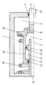
- the single figure shows a partial section through an embodiment of a hydraulic actuator according to the invention.
- the representation is greatly simplified.
- a housing 1 closes off the hydraulic actuator from the outside.
- This housing 1 is essentially cylindrical extends along a longitudinal axis 2 and has an interior 3 filled with low-pressure oil.
- the housing 1 is penetrated by a valve rod 4.
- a seal 5 seals the interior 3 from the environment.
- In the housing 1 leads on the left side a central bore 6 through which the low pressure oil is fed in and out. The bore 6 leads into an intermediate volume 7, which is connected to the interior 3 through an opening 8.
- the bore 6 has a wall 9, the side facing the interior 3 serves as a guide for a drive piston 10 and at the same time as a wall of a drive volume 11.
- a collar 13 placed on the wall 9 and provided with a seal 12 closes off the drive volume 11 from the intermediate volume 7 and at the same time guides the drive piston 10.
- the drive piston 10 is provided with a seal which seals the drive volume 11 from the interior 2.
- the drive piston 10 is connected to the valve rod 4 via a spring plate 15; the separation points of this assembly are not shown.
- the spring plate 15 extends into the interior 3. It has a receptacle for a spiral spring 16, the other end of which is supported against the left side of the housing 1.
- the spiral spring 16 wants to press the spring plate 15 in the direction of an arrow 17 to the right.
- the drive volume 11 lies in the area within the spiral spring 16; the longitudinal axis 2 represents the central axis for both elements.
- the drive volume is pressurized with high-pressure oil via at least one channel (not shown)
- the figure is considered in more detail.
- the spiral spring 16 presses the valve rod 4 to the right in the direction of the arrow 17.
- the valve actuated via this valve rod 4 is then closed.
- This position can also be used as a fail safe position be designated.
- the drive volume 11 is pressurized with high-pressure oil, the drive piston 10 and with it the valve rod 4 move to the left, the valve is opened.
- the high pressure oil has a pressure in the range of 100 to 200 bar.
- the stroke of the actuator is regulated with the amount of high pressure oil supplied.
- the seals 12 and 14, which seal the drive volume 11 from the adjacent volumes filled with low-pressure oil and serving as a safety volume, namely from the intermediate volume 7 and the interior 3, are highly stressed, so that failure of these seals 12 and 14 can never be completely ruled out.
- the concentric arrangement of the drive volume 11 within the spiral spring 16 enables a compact and compact Type of actuator.
- the available safety volume can advantageously also be used at the same time as space for the spiral spring 16.
- disc springs which are layered as a package can also be used.
- a combination of disc springs with spiral springs is also possible, so that the spring characteristics can be adapted to the operating requirements of the actuator.
- the actuator With this actuator, no high-pressure oil can get into the surrounding atmosphere if a seal defect should occur. This prevents consequential damage such as fires, injuries and contamination of the system.
- the operational reliability of such an actuator is significantly increased.
- the actuator can advantageously be built compactly, which increases its economy.
Landscapes
- Engineering & Computer Science (AREA)
- General Engineering & Computer Science (AREA)
- Mechanical Engineering (AREA)
- Actuator (AREA)
- Fluid-Driven Valves (AREA)
- Gear-Shifting Mechanisms (AREA)
- Control Of Transmission Device (AREA)
Abstract
Description
- Die Erfindung geht aus von einem hydraulischen Stellantrieb für die Betätigung eines Ventils. Der Stellantrieb weist ein mit Hochdrucköl beaufschlagtes und von einem Antriebskolben begrenztes Antriebsvolumen auf. Ein Federelement wirkt entgegengesetzt zum Hochdrucköl auf den Antriebskolben ein.
- Es sind derartige hydraulische Stellantriebe für die Betätigung von Ventilen in Kraftwerken bekannt, die mit Hochdrucköl betätigt werden und die durch ein eingebautes Federelement wieder in die Ausgangslage zurückbewegt werden, wenn der Druck des Hochdrucköls nachlässt bzw. wenn das Hochdrucköl abgepumpt wird. In der Regel sind dabei im Stellantrieb das Antriebsvolumen und das Federelement hintereinander auf einer gemeinsamen Achse angeordnet. Diese Bauform benötigt vergleichsweise viel Platz in axialer Richtung. Zudem grenzt das Antriebsvolumen mindestens einseitig an die Umgebungsluft, sodass bei einem Dichtungsschaden Hochdrucköl aus dem Antriebsvolumen austreten und die Umwelt gefährden kann. So können beispielsweise Brände durch auf heisse Teile spritzendes Hochdrucköl ausgelöst werden.
- Hier will die Erfindung Abhilfe schaffen. Die Erfindung, wie sie in den Ansprüchen gekennzeichnet ist, löst die Aufgabe, einen hydraulischen Stellantrieb zu schaffen, bei welchem aus dem Antriebsvolumen austretendes Hochdrucköl keine Folgeschäden verursachen kann.
- Die durch die Erfindung erreichten Vorteile sind im wesentlichen darin zu sehen, dass der hydraulische Stellantrieb sicherer zu betreiben ist. Zusätzliche Schilde, welchen gegen eventuell austretendes Hochdrucköl schützen können, werden hier nicht benötigt. Der hydraulische Stellantrieb kann vergleichsweise kompakt gebaut werden, was sich auch auf seine Wirtschaftlichkeit positiv auswirkt.
- Die weiteren Ausgestaltungen der Erfindung sind Gegenstände der abhängigen Ansprüche.
- Die Erfindung, ihre Weiterbildung und die damit erzielbaren Vorteile werden nachstehend anhand der Zeichnung, welche lediglich einen Ausführungsweg darstellt, näher erläutert.
- Die einzige Figur zeigt einen Teilschnitt durch eine Ausführungsform eines erfindungsgemässen hydraulischen Stellantriebs. Die Darstellung ist stark vereinfacht.
- In der Erfindung ist eine Prinzipskizze eines hydraulischen Stellantriebs dargestellt. Seine notwendigerweise vorhandenen Befestigungselemente sind nicht dargestellt ebensowenig wie die Hydraulikzuleitungen und etwaige elektrohydraulische Betätigungselemente für den Stellantrieb wie z.B. Proportionalventile. Ferner ist die üblicherweise vorhandene Hubüberwachung des Stellantriebs ebenfalls nicht dargestellt. Ein Gehäuse 1 schliesst den hydraulischen Stellantrieb nach aussen ab. Dieses Gehäuse 1 ist im wesentlichen zylindrisch entlang einer Längsachse 2 erstreckt ausgebildet und weist einen mit Niederdrucköl aufgefüllten Innenraum 3 auf. Auf seiner rechten Seite wird das Gehäuse 1 von einer Ventilstange 4 durchdrungen. Eine Dichtung 5 dichtet den Innenraum 3 gegen die Umgebung ab. In das Gehäuse 1 führt auf der linken Seite eine zentrale Bohrung 6, durch welche das Niederdrucköl zu und abgeführt wird. Die Bohrung 6 führt in ein Zwischenvolumen 7, welches durch eine Öffnung 8 mit dem Innenraum 3 verbunden ist.
- Die Bohrung 6 weist eine Wand 9 auf, deren dem Innenraum 3 zugewandte Seite als Führung für einen Antriebskolben 10 und gleichzeitig als eine Wand eines Antriebsvolumens 11 dient. Ein auf die Wand 9 aufgesetzter und mit einer Dichtung 12 versehener Bund 13 schliesst das Antriebsvolumen 11 gegen das Zwischenvolumen 7 ab und führt gleichzeitig den Antriebskolben 10. Der Antriebskolben 10 ist mit einer Dichtung versehen, welche das Antriebsvolumen 11 gegen den Innenraum 2 abdichtet. Der Antriebskolben 10 ist über einen Federteller 15 mit der Ventilstange 4 verbunden; die Trennstellen dieser Baugruppe sind nicht dargestellt. Der Federteller 15 erstreckt sich in den Innenraum 3. Er weist eine Aufnahme für eine Spiralfeder 16 auf, deren anderes Ende sich gegen die linke Seite des Gehäuses 1 abstützt. Die Spiralfeder 16 will den Federteller 15 in Richtung eines Pfeiles 17 nach rechts drücken. Das Antriebsvolumen 11 liegt im Bereich innerhalb der Spiralfeder 16; die Längsachse 2 stellt die zentrale Achse für beide Elemente dar. Das Antriebsvolumen wird über mindestens einen, nicht dargestellten, in die Wand 9 eingelassenen Kanal mit Hochdrucköl beaufschlagt.
- Zur Erläuterung der Wirkungsweise sei die Figur näher betrachtet. Im Ruhezustand, wenn kein nennenswerter Druck das Antriebsvolumen 11 beaufschlagt, drückt die Spiralfeder 16 die Ventilstange 4 nach rechts in Richtung des Pfeiles 17. Das über diese Ventilstange 4 betätigte Ventil ist dann geschlossen. Diese Stellung kann auch als fail safe-Stellung bezeichnet werden. Wird das Antriebsvolumen 11 mit Hochdrucköl beaufschlagt, so bewegt sich der Antriebskolben 10 und mit ihm die Ventilstange 4 nach links, das Ventil wird geöffnet. Das Hochdrucköl weist einen Druck im Bereich von 100 bis 200 bar auf. Mit der Menge des zugeführten Hochdrucköls wird der Hub des Stellantriebes geregelt. Die Dichtungen 12 und 14, welche das Antriebsvolumen 11 abdichten gegenüber den mit Niederdrucköl gefüllten, als Sicherheitsvolumen dienenden benachbarten Volumina, nämlich gegenüber dem Zwischenvolumen 7 und dem Innenraum 3, sind hochbeansprucht, sodass ein Versagen dieser Dichtungen 12 und 14 nie ganz ausgeschlossen werden kann.
- Ein derartiges Versagen verursacht hier jedoch keine Folgeschäden, da das aus dem Antriebsvolumen 11 entweichende Hochdrucköl im Sicherheitsvolumen aufgefangen wird. Der Druck des Niederdrucköls im Sicherheitsvolumen, welcher beispielsweise im Normalfall 5 bar beträgt, wird durch das hinzutretende Hochdrucköl auf maximal 7 bis 8 bar angehoben. Die Dimensionen der Dichtungsspalte, durch die das Hochdrucköl im Fehlerfall austritt, begrenzen diesen Ölstrom, sodass im Sicherheitsvolumen kein zu hoher Druck auftreten kann. Zudem ist das Sicherheitsvolumen grösser ausgebildet als das Antriebsvolumen 11, sodass auch hier eine gewisse redundante Sicherheit eingebaut ist. Das Sicherheitsvolumen ist etwa zehn- bis fünfzigfach grösser ausgebildet als das Antriebsvolumen 11, sodass mit grosser Sicherheit Druckstösse, die von austretendem Hochdrucköl herrühren, abgeflacht werden auf ungefährliche Werte. Nachströmendes Hochdrucköl kann ebenfalls keine unzulässige Druckerhöhung im Sicherheitsvolumen verursachen, da die an der Bohrung 6 angeschlossenen Leitungen für das Niederdrucköl einen hinreichend grossen Querschnitt aufweisen, um mögliche Druckerhöhungen abführen zu können.
- Die konzentrische Anordnung des Antriebsvolumens 11 innerhalb der Spiralfeder 16 ermöglicht eine gedrängte und kompakte Bauart des Stellantriebs. Das vorhandene Sicherheitsvolumen kann vorteilhaft gleichzeitig auch als Raum für die Spiralfeder 16 genutzt werden. Je nach Bedarf können statt der Spiralfeder 16 auch Tellerfedern, die als Paket geschichtet werden, eingesetzt werden. Ferner ist auch eine Kombination von Tellerfedern mit Spiralfedern möglich, sodass die Federcharakteristik an die Betriebsanforderungen des Stellantriebes angepasst werden kann.
- Bei diesem Stellantrieb kann kein Hochdrucköl in die umgebende Atmosphäre gelangen, wenn ein Dichtungsdefekt auftreten sollte. Damit werden Folgeschäden wie Brände, Verletzungen und Verschmutzung der Anlage vermieden. Die Betriebssicherheit eines solchen Stellantriebes ist wesentlich erhöht. Zudem lässt sich der Stellantrieb vorteilhaft kompakt bauen, was seine Wirtschaftlichkeit steigert.
Claims (5)
dadurch gekennzeichnet,
- dass das Antriebsvolumen (11) vollständig von einem mit Niederdrucköl gefüllten Sicherheitsvolumen umgeben ist.
dadurch gekennzeichnet,
- dass das Antriebsvolumen (11) und das Federelement konzentrisch angeordnet sind, wobei das Federelement das Antriebsvolumen (11) konzentrisch umgibt.
dadurch gekennzeichnet,
- dass als Federelement ein Tellerfedernpaket oder eine Spiralfeder (16) oder eine Kombination beider erwähnter Federarten vorgesehen ist.
dadurch gekennzeichnet,
- dass das Sicherheitsvolumen grösser ausgebildet ist als das Antriebsvolumen (11).
dadurch gekennzeichnet,
- dass das Sicherheitsvolumen zehn- bis fünfzigfach grösser ausgebildet ist als das Antriebsvolumen (11).
Applications Claiming Priority (2)
| Application Number | Priority Date | Filing Date | Title |
|---|---|---|---|
| CH318089 | 1989-09-01 | ||
| CH3180/89 | 1989-09-01 |
Publications (2)
| Publication Number | Publication Date |
|---|---|
| EP0415046A1 true EP0415046A1 (de) | 1991-03-06 |
| EP0415046B1 EP0415046B1 (de) | 1993-10-06 |
Family
ID=4250357
Family Applications (1)
| Application Number | Title | Priority Date | Filing Date |
|---|---|---|---|
| EP90113401A Expired - Lifetime EP0415046B1 (de) | 1989-09-01 | 1990-07-13 | Hydraulischer Stellantrieb |
Country Status (7)
| Country | Link |
|---|---|
| US (1) | US5070766A (de) |
| EP (1) | EP0415046B1 (de) |
| JP (1) | JPH0392603A (de) |
| CA (1) | CA2021448C (de) |
| DE (1) | DE59002996D1 (de) |
| DK (1) | DK0415046T3 (de) |
| ES (1) | ES2046605T3 (de) |
Cited By (1)
| Publication number | Priority date | Publication date | Assignee | Title |
|---|---|---|---|---|
| EP2270958A1 (de) * | 2009-07-03 | 2011-01-05 | Société de Mécanique Magnétique | Eingekapselte rotierende Maschine und ihr Herstellungsverfahren |
Families Citing this family (1)
| Publication number | Priority date | Publication date | Assignee | Title |
|---|---|---|---|---|
| USD1001843S1 (en) * | 2021-03-29 | 2023-10-17 | Robert Bosch Gmbh | Subsea valve actuator |
Citations (5)
| Publication number | Priority date | Publication date | Assignee | Title |
|---|---|---|---|---|
| US3379405A (en) * | 1966-01-03 | 1968-04-23 | Acf Ind Inc | Valve |
| EP0149908A2 (de) * | 1984-01-09 | 1985-07-31 | Moog Inc. | Dichtungssatz für druckmittelbetriebene Betätigungseinrichtung |
| CH651900A5 (en) * | 1981-04-01 | 1985-10-15 | Hydrowatt Syst | Piston/cylinder arrangement having a seal liable to leakage |
| US4601457A (en) * | 1985-10-01 | 1986-07-22 | Baker Cac, Inc. | Fluid pressure actuator valve |
| US4744386A (en) * | 1987-08-11 | 1988-05-17 | Cameron Iron Works Usa, Inc. | Modular hydraulic actuator |
Family Cites Families (10)
| Publication number | Priority date | Publication date | Assignee | Title |
|---|---|---|---|---|
| GB721731A (en) * | 1949-10-28 | 1955-01-12 | Mini Of Supply | Improvements in the production of magnetic fluxgates |
| NL106835C (de) * | 1957-02-15 | 1963-07-15 | ||
| US2976845A (en) * | 1959-12-18 | 1961-03-28 | Modernair Corp | Pneumatic-hydraulic drive cylinder |
| US3331291A (en) * | 1965-07-15 | 1967-07-18 | Royal Industries | Emergency brake actuator |
| US3726187A (en) * | 1971-02-22 | 1973-04-10 | Westinghouse Electric Corp | Servo-actuator mechanism |
| US3741075A (en) * | 1971-03-30 | 1973-06-26 | Plunger Lift Elevator Inc | Safety apparatus for hydraulic elevator jacks |
| DE2558959C2 (de) * | 1975-12-29 | 1977-12-22 | Siemens AG, 1000 Berlin und 8000 München | Hydraulischer Stellantrieb für Armaturen |
| US4601456A (en) * | 1985-03-14 | 1986-07-22 | Jan Shaw G | Apparatus for forming a concrete structure |
| US4585207A (en) * | 1985-09-03 | 1986-04-29 | Joy Manufacturing Company | Expanding gate valve with pneumatic actuator |
| US4877217A (en) * | 1988-10-27 | 1989-10-31 | Bowen Tools, Inc. | Fail-safe blowout preventer |
-
1990
- 1990-07-13 ES ES199090113401T patent/ES2046605T3/es not_active Expired - Lifetime
- 1990-07-13 EP EP90113401A patent/EP0415046B1/de not_active Expired - Lifetime
- 1990-07-13 DE DE90113401T patent/DE59002996D1/de not_active Expired - Fee Related
- 1990-07-13 DK DK90113401.5T patent/DK0415046T3/da active
- 1990-07-18 CA CA002021448A patent/CA2021448C/en not_active Expired - Fee Related
- 1990-07-26 US US07/557,786 patent/US5070766A/en not_active Expired - Fee Related
- 1990-08-30 JP JP2226803A patent/JPH0392603A/ja active Pending
Patent Citations (5)
| Publication number | Priority date | Publication date | Assignee | Title |
|---|---|---|---|---|
| US3379405A (en) * | 1966-01-03 | 1968-04-23 | Acf Ind Inc | Valve |
| CH651900A5 (en) * | 1981-04-01 | 1985-10-15 | Hydrowatt Syst | Piston/cylinder arrangement having a seal liable to leakage |
| EP0149908A2 (de) * | 1984-01-09 | 1985-07-31 | Moog Inc. | Dichtungssatz für druckmittelbetriebene Betätigungseinrichtung |
| US4601457A (en) * | 1985-10-01 | 1986-07-22 | Baker Cac, Inc. | Fluid pressure actuator valve |
| US4744386A (en) * | 1987-08-11 | 1988-05-17 | Cameron Iron Works Usa, Inc. | Modular hydraulic actuator |
Cited By (3)
| Publication number | Priority date | Publication date | Assignee | Title |
|---|---|---|---|---|
| EP2270958A1 (de) * | 2009-07-03 | 2011-01-05 | Société de Mécanique Magnétique | Eingekapselte rotierende Maschine und ihr Herstellungsverfahren |
| FR2947678A1 (fr) * | 2009-07-03 | 2011-01-07 | Mecanique Magnetique Sa | Machine tournante chemisee et son procede de fabrication |
| US8148861B2 (en) | 2009-07-03 | 2012-04-03 | Societe De Mecanique Magnetique | Canned or sleeved rotary machine and method of manufacturing it |
Also Published As
| Publication number | Publication date |
|---|---|
| ES2046605T3 (es) | 1994-02-01 |
| DK0415046T3 (da) | 1994-02-14 |
| CA2021448C (en) | 2000-03-28 |
| DE59002996D1 (de) | 1993-11-11 |
| US5070766A (en) | 1991-12-10 |
| JPH0392603A (ja) | 1991-04-17 |
| EP0415046B1 (de) | 1993-10-06 |
| CA2021448A1 (en) | 1991-03-02 |
Similar Documents
| Publication | Publication Date | Title |
|---|---|---|
| DE60310504T2 (de) | Ventil mit Druckausgleichkolben | |
| DE2714160A1 (de) | Steuergeraet fuer pneumatische einrichtungen, bestehend aus einem verteiler und einem sockel | |
| DE3839317C2 (de) | Elektromotorischer Antrieb für ein Stellglied | |
| EP3256743B1 (de) | Ventil mit einem in einem ventilgehäuse längsverfahrbar geführten steuerschieber | |
| DE3329734C2 (de) | ||
| EP0433791A1 (de) | Antrieb für ein Speiseventil | |
| EP0451543A1 (de) | Antrieb für ein Dampfstellventil | |
| DE2551126A1 (de) | Hydropneumatischer ventilantrieb | |
| EP0415046B1 (de) | Hydraulischer Stellantrieb | |
| DE2651758A1 (de) | Druckausgeglichenes ventil | |
| DE102018119347A1 (de) | Flurförderzeug mit hydraulischem Hubsystem und elektronischer Fehlfunktionsabsicherung des Hubsystems | |
| DE102021128103A1 (de) | Pneumatisch-hydraulisches steuerventil | |
| DE202012009568U1 (de) | Hydraulischer Hubzylinder und Hebesystem mit einem solchen Hubzylinder | |
| DE10219718A1 (de) | Hydraulische Ventilanordnung | |
| DE4414779C1 (de) | Multifunktionsventil | |
| DE4320937A1 (de) | Stellantrieb für ein Regelventil | |
| EP3585720B1 (de) | Fangzylinder für ein lasthebemittel sowie lasthebemittel mit einem fangzylinder | |
| DE2717418A1 (de) | Vorrichtung zur druckpruefung und steuerung eines sicherheitsventils | |
| DE19705827A1 (de) | Hydrauliksysteme | |
| EP3728821A1 (de) | Ventilvorrichtung für eine verbrennungskraftmaschine | |
| DE102023101994A1 (de) | Stellvorrichtung | |
| DE3333004A1 (de) | Vorrichtung zum verdichten von koernigen formstoffen | |
| DE102006001893A1 (de) | Parkbremse für ein Kraftfahrzeug | |
| DE102006003660B4 (de) | Einrichtung zur Sicherung der Bewegungsreihenfolge von mindestens zwei fluidbetätigten Verdrängereinheiten | |
| DE2915505A1 (de) | Kraftbegrenzer fuer eine stellstange |
Legal Events
| Date | Code | Title | Description |
|---|---|---|---|
| PUAI | Public reference made under article 153(3) epc to a published international application that has entered the european phase |
Free format text: ORIGINAL CODE: 0009012 |
|
| AK | Designated contracting states |
Kind code of ref document: A1 Designated state(s): BE CH DE DK ES FR GB IT LI SE |
|
| 17P | Request for examination filed |
Effective date: 19910829 |
|
| 17Q | First examination report despatched |
Effective date: 19930304 |
|
| GRAA | (expected) grant |
Free format text: ORIGINAL CODE: 0009210 |
|
| AK | Designated contracting states |
Kind code of ref document: B1 Designated state(s): BE CH DE DK ES FR GB IT LI SE |
|
| REF | Corresponds to: |
Ref document number: 59002996 Country of ref document: DE Date of ref document: 19931111 |
|
| ITF | It: translation for a ep patent filed | ||
| GBT | Gb: translation of ep patent filed (gb section 77(6)(a)/1977) |
Effective date: 19931215 |
|
| ET | Fr: translation filed | ||
| REG | Reference to a national code |
Ref country code: ES Ref legal event code: FG2A Ref document number: 2046605 Country of ref document: ES Kind code of ref document: T3 |
|
| REG | Reference to a national code |
Ref country code: DK Ref legal event code: T3 |
|
| PG25 | Lapsed in a contracting state [announced via postgrant information from national office to epo] |
Ref country code: SE Effective date: 19940714 |
|
| PG25 | Lapsed in a contracting state [announced via postgrant information from national office to epo] |
Ref country code: LI Effective date: 19940731 Ref country code: CH Effective date: 19940731 Ref country code: BE Effective date: 19940731 |
|
| PLBE | No opposition filed within time limit |
Free format text: ORIGINAL CODE: 0009261 |
|
| STAA | Information on the status of an ep patent application or granted ep patent |
Free format text: STATUS: NO OPPOSITION FILED WITHIN TIME LIMIT |
|
| 26N | No opposition filed | ||
| BERE | Be: lapsed |
Owner name: ASEA BROWN BOVERI A.G. Effective date: 19940731 |
|
| EUG | Se: european patent has lapsed |
Ref document number: 90113401.5 Effective date: 19950210 |
|
| REG | Reference to a national code |
Ref country code: CH Ref legal event code: PL |
|
| EUG | Se: european patent has lapsed |
Ref document number: 90113401.5 |
|
| PGFP | Annual fee paid to national office [announced via postgrant information from national office to epo] |
Ref country code: ES Payment date: 19970718 Year of fee payment: 8 |
|
| PG25 | Lapsed in a contracting state [announced via postgrant information from national office to epo] |
Ref country code: ES Free format text: LAPSE BECAUSE OF THE APPLICANT RENOUNCES Effective date: 19980714 |
|
| PGFP | Annual fee paid to national office [announced via postgrant information from national office to epo] |
Ref country code: GB Payment date: 20000614 Year of fee payment: 11 |
|
| PGFP | Annual fee paid to national office [announced via postgrant information from national office to epo] |
Ref country code: DK Payment date: 20000626 Year of fee payment: 11 |
|
| PGFP | Annual fee paid to national office [announced via postgrant information from national office to epo] |
Ref country code: FR Payment date: 20000629 Year of fee payment: 11 Ref country code: DE Payment date: 20000629 Year of fee payment: 11 |
|
| REG | Reference to a national code |
Ref country code: ES Ref legal event code: FD2A Effective date: 20001009 |
|
| PG25 | Lapsed in a contracting state [announced via postgrant information from national office to epo] |
Ref country code: GB Free format text: LAPSE BECAUSE OF NON-PAYMENT OF DUE FEES Effective date: 20010713 Ref country code: DK Free format text: LAPSE BECAUSE OF NON-PAYMENT OF DUE FEES Effective date: 20010713 |
|
| GBPC | Gb: european patent ceased through non-payment of renewal fee |
Effective date: 20010713 |
|
| REG | Reference to a national code |
Ref country code: DK Ref legal event code: EBP |
|
| PG25 | Lapsed in a contracting state [announced via postgrant information from national office to epo] |
Ref country code: FR Free format text: LAPSE BECAUSE OF NON-PAYMENT OF DUE FEES Effective date: 20020329 |
|
| PG25 | Lapsed in a contracting state [announced via postgrant information from national office to epo] |
Ref country code: DE Free format text: LAPSE BECAUSE OF NON-PAYMENT OF DUE FEES Effective date: 20020501 |
|
| REG | Reference to a national code |
Ref country code: FR Ref legal event code: ST |
|
| PG25 | Lapsed in a contracting state [announced via postgrant information from national office to epo] |
Ref country code: IT Free format text: LAPSE BECAUSE OF NON-PAYMENT OF DUE FEES;WARNING: LAPSES OF ITALIAN PATENTS WITH EFFECTIVE DATE BEFORE 2007 MAY HAVE OCCURRED AT ANY TIME BEFORE 2007. THE CORRECT EFFECTIVE DATE MAY BE DIFFERENT FROM THE ONE RECORDED. Effective date: 20050713 |