EP0415260B1 - Distributeur de chauffage ou de bouilloire - Google Patents
Distributeur de chauffage ou de bouilloire Download PDFInfo
- Publication number
- EP0415260B1 EP0415260B1 EP90116105A EP90116105A EP0415260B1 EP 0415260 B1 EP0415260 B1 EP 0415260B1 EP 90116105 A EP90116105 A EP 90116105A EP 90116105 A EP90116105 A EP 90116105A EP 0415260 B1 EP0415260 B1 EP 0415260B1
- Authority
- EP
- European Patent Office
- Prior art keywords
- flanges
- pipe
- connecting pieces
- crowns
- heating
- Prior art date
- Legal status (The legal status is an assumption and is not a legal conclusion. Google has not performed a legal analysis and makes no representation as to the accuracy of the status listed.)
- Expired - Lifetime
Links
Images
Classifications
-
- F—MECHANICAL ENGINEERING; LIGHTING; HEATING; WEAPONS; BLASTING
- F24—HEATING; RANGES; VENTILATING
- F24D—DOMESTIC- OR SPACE-HEATING SYSTEMS, e.g. CENTRAL HEATING SYSTEMS; DOMESTIC HOT-WATER SUPPLY SYSTEMS; ELEMENTS OR COMPONENTS THEREFOR
- F24D3/00—Hot-water central heating systems
- F24D3/10—Feed-line arrangements, e.g. providing for heat-accumulator tanks, expansion tanks ; Hydraulic components of a central heating system
- F24D3/1058—Feed-line arrangements, e.g. providing for heat-accumulator tanks, expansion tanks ; Hydraulic components of a central heating system disposition of pipes and pipe connections
- F24D3/1066—Distributors for heating liquids
- F24D3/1075—Built up from modules
-
- F—MECHANICAL ENGINEERING; LIGHTING; HEATING; WEAPONS; BLASTING
- F16—ENGINEERING ELEMENTS AND UNITS; GENERAL MEASURES FOR PRODUCING AND MAINTAINING EFFECTIVE FUNCTIONING OF MACHINES OR INSTALLATIONS; THERMAL INSULATION IN GENERAL
- F16L—PIPES; JOINTS OR FITTINGS FOR PIPES; SUPPORTS FOR PIPES, CABLES OR PROTECTIVE TUBING; MEANS FOR THERMAL INSULATION IN GENERAL
- F16L25/00—Construction or details of pipe joints not provided for in, or of interest apart from, groups F16L13/00 - F16L23/00
- F16L25/14—Joints for pipes of different diameters or cross-section
-
- F—MECHANICAL ENGINEERING; LIGHTING; HEATING; WEAPONS; BLASTING
- F16—ENGINEERING ELEMENTS AND UNITS; GENERAL MEASURES FOR PRODUCING AND MAINTAINING EFFECTIVE FUNCTIONING OF MACHINES OR INSTALLATIONS; THERMAL INSULATION IN GENERAL
- F16L—PIPES; JOINTS OR FITTINGS FOR PIPES; SUPPORTS FOR PIPES, CABLES OR PROTECTIVE TUBING; MEANS FOR THERMAL INSULATION IN GENERAL
- F16L41/00—Branching pipes; Joining pipes to walls
- F16L41/02—Branch units, e.g. made in one piece, welded, riveted
- F16L41/03—Branch units, e.g. made in one piece, welded, riveted comprising junction pieces for four or more pipe members
-
- F—MECHANICAL ENGINEERING; LIGHTING; HEATING; WEAPONS; BLASTING
- F24—HEATING; RANGES; VENTILATING
- F24D—DOMESTIC- OR SPACE-HEATING SYSTEMS, e.g. CENTRAL HEATING SYSTEMS; DOMESTIC HOT-WATER SUPPLY SYSTEMS; ELEMENTS OR COMPONENTS THEREFOR
- F24D3/00—Hot-water central heating systems
- F24D3/10—Feed-line arrangements, e.g. providing for heat-accumulator tanks, expansion tanks ; Hydraulic components of a central heating system
- F24D3/1058—Feed-line arrangements, e.g. providing for heat-accumulator tanks, expansion tanks ; Hydraulic components of a central heating system disposition of pipes and pipe connections
- F24D3/1066—Distributors for heating liquids
Definitions
- the invention relates to a heating or boiler manifold, made up of modular prefabricated basic housing units and with a plurality of fixed outlet connections of the same nominal size, primarily for large systems.
- a distributor in which the outgoing line connections as lying in a row, frustoconical pipe sockets are formed; Markings are placed on the lateral surface of the line connections at predetermined longitudinal intervals, the position of which is matched to the cone angle of the line connections.
- the coordination is chosen so that when a pipe socket is cut to length along a marking, there is such a residual height of the pipe socket and at the upper end such an opening cross section that when the pump or a valve with standardized dimensions (overall height and connection cross section) is fitted, the actuating member or the Center of this device is at the same height above the distributor housing as when placing a correspondingly smaller device on the pipe stub that has not been cut to length.
- the pipe sockets are higher, their opening cross-section is smaller and so matched to the connection cross-section of the device to be attached that the overall height of the device from the connection point to the central height or operating level of the device is again the same overall height as for a larger one, attached to the cut-off pipe socket Device results.
- an extremely expedient and fail-safe installation of the pipe distributor can be achieved.
- On the outer ends of the Pipe sockets can be welded onto either connecting flanges or connecting threads.
- the invention is therefore also based on the object of providing a pipe distributor in which the line connections branching off from the flow space and the return space are aligned with one another in the longitudinal direction, which is suitable for large nominal widths in manufacture and is therefore inexpensive and to the full extent in the workshop can be prefabricated.
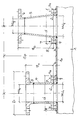
- the new distributor consists of a housing 1 of any length and is provided with any number of outlets 2 already fixed in the workshop and one and the same nominal nominal width "NW1"; It can be advantageous if the housing-side outlets 2 are designed as flange-free flange rings 2, directly welded onto the top of the housing la, in such a way that they have the same height "h” industrial flanges, ie special flanges with a smaller outside diameter "d" than that "D” of Represent DIN flanges 3 of the same nominal size "NW1".
- the pipe attachments 4, reducers 5 or the like to be connected to these outlets 2 on the construction site each also have corresponding special flanges 4a and 5a on the foot side and also, also prefabricated in the workshop, have an overall height of "H 1 or H 2", which means that Standard flanges 3 or 6 connected fittings or the like brings to the same average spindle height "Sp".
- the new system is completed by the fact that the special flanges 4a and 5a with their top or reducers 4 or 5 are formed in one piece and are connected to the outlets 2 by screws 7, preferably the upper flanges 4a and 5a through holes 8 and the associated counter flanges of Outlets 2 threaded holes 9.
- the present invention now also makes it possible for large distributors with a large number of outlets 2 to produce them in a simple manner and to complete them directly on site without reworking; this considerably simplifies planning work and storage.
Landscapes
- Engineering & Computer Science (AREA)
- General Engineering & Computer Science (AREA)
- Mechanical Engineering (AREA)
- Physics & Mathematics (AREA)
- Thermal Sciences (AREA)
- Chemical & Material Sciences (AREA)
- Combustion & Propulsion (AREA)
- Branch Pipes, Bends, And The Like (AREA)
- Steam Or Hot-Water Central Heating Systems (AREA)
- Mounting, Exchange, And Manufacturing Of Dies (AREA)
Claims (3)
- Distributeur pour chauffage ou chaudière, de préférence pour de grandes installations, composé d'unités de base de boîtier (1), de plusieurs tubulures de sortie (2) de même largeur nominale (NW₁) montées à l'avance de façon modulaire sur le boîtier (1) et de raccords de tube (4, 5) raccordés à ces tubulures de sortie (2) avec un raccord pour la liaison avec des appareils de robinetterie de dimensions aux normes, les raccords de tube possédant une hauteur (H1, H2) correspondant à la section d'ouverture (NW₁, NW₂) du raccord correspondant, qui amène les appareils de robinetterie devant y être raccordés à la même hauteur de tige (Sp) moyenne, caractérisé en ce que les tubulures de sortie (2) sont conçues comme des brides industrielles de même hauteur (h), donc comme des brides spéciales avec un diamètre extérieur (d) plus petit que celui (D) des brides aux normes DIN (3) de même largeur nominale (NW₁) et les raccords de tube (4, 5) présentent également des brides spéciales (4a, 5a) à la base et des brides aux normes DIN (3, 6) de l'autre côté.
- Distributeur pour chauffage ou chaudière selon la revendication 1, caractérisé en ce que les brides spéciales (4a, 5a) sont formées avec les raccords de tube (4, 5) correspondants par moulage d'un seul tenant et reliées par des vis (7) aux tubulures de sortie (2), les brides (4a, 5a) des raccords de tube présentant de préférence des trous traversants (8) et les brides des tubulures de sortie (2) des trous filetés (9).
- Distributeur pour chauffage ou chaudière selon la revendication 1 ou 2, caractérisé en ce que les tubulures de sortie sont conçues comme des anneaux de bride (2) soudés directement sur la face supérieure (1a) du boîtier.
Priority Applications (1)
| Application Number | Priority Date | Filing Date | Title |
|---|---|---|---|
| AT90116105T ATE103686T1 (de) | 1989-08-30 | 1990-08-22 | Heizungs- bzw. kesselverteiler. |
Applications Claiming Priority (2)
| Application Number | Priority Date | Filing Date | Title |
|---|---|---|---|
| DE3928731 | 1989-08-30 | ||
| DE3928731A DE3928731A1 (de) | 1989-08-30 | 1989-08-30 | Heizungs- bzw. kesselverteiler |
Publications (2)
| Publication Number | Publication Date |
|---|---|
| EP0415260A1 EP0415260A1 (fr) | 1991-03-06 |
| EP0415260B1 true EP0415260B1 (fr) | 1994-03-30 |
Family
ID=6388216
Family Applications (1)
| Application Number | Title | Priority Date | Filing Date |
|---|---|---|---|
| EP90116105A Expired - Lifetime EP0415260B1 (fr) | 1989-08-30 | 1990-08-22 | Distributeur de chauffage ou de bouilloire |
Country Status (3)
| Country | Link |
|---|---|
| EP (1) | EP0415260B1 (fr) |
| AT (1) | ATE103686T1 (fr) |
| DE (2) | DE3928731A1 (fr) |
Cited By (1)
| Publication number | Priority date | Publication date | Assignee | Title |
|---|---|---|---|---|
| EP1701097A2 (fr) | 2005-03-09 | 2006-09-13 | Comfort-Sinusverteiler GmbH | Distributeur, notament pour installations de chauffage |
Families Citing this family (4)
| Publication number | Priority date | Publication date | Assignee | Title |
|---|---|---|---|---|
| JPH09317599A (ja) | 1996-05-22 | 1997-12-09 | Usui Internatl Ind Co Ltd | コモンレールおよびその製造方法 |
| US6543811B1 (en) * | 1996-12-02 | 2003-04-08 | Robert W. Campbell | Pipe flange assembly |
| US5947528A (en) * | 1996-12-02 | 1999-09-07 | Campbell; Robert W. | Pipe flange assembly |
| JP3745211B2 (ja) | 2000-09-21 | 2006-02-15 | 柿沼金属精機株式会社 | 分岐ジョイント |
Family Cites Families (2)
| Publication number | Priority date | Publication date | Assignee | Title |
|---|---|---|---|---|
| DE2748673C2 (de) * | 1977-10-29 | 1985-07-04 | Antonio Penne Pescara Rietti | Verteileranlage für zirkulierendes Medium |
| DE3012854A1 (de) * | 1980-04-02 | 1981-10-08 | Maile + Grammer Gmbh, 7407 Rottenburg | Rohrleitungsverteiler, insbesondere fuer warmwasserheuzungen |
-
1989
- 1989-08-30 DE DE3928731A patent/DE3928731A1/de not_active Withdrawn
-
1990
- 1990-08-22 DE DE90116105T patent/DE59005171D1/de not_active Expired - Fee Related
- 1990-08-22 EP EP90116105A patent/EP0415260B1/fr not_active Expired - Lifetime
- 1990-08-22 AT AT90116105T patent/ATE103686T1/de active
Cited By (1)
| Publication number | Priority date | Publication date | Assignee | Title |
|---|---|---|---|---|
| EP1701097A2 (fr) | 2005-03-09 | 2006-09-13 | Comfort-Sinusverteiler GmbH | Distributeur, notament pour installations de chauffage |
Also Published As
| Publication number | Publication date |
|---|---|
| DE59005171D1 (de) | 1994-05-05 |
| DE3928731A1 (de) | 1991-03-07 |
| EP0415260A1 (fr) | 1991-03-06 |
| ATE103686T1 (de) | 1994-04-15 |
Similar Documents
| Publication | Publication Date | Title |
|---|---|---|
| EP0715112A2 (fr) | Appareil pour connexion simultanée d'électrovannes | |
| DE3214775C2 (de) | Vorrichtung zum Übergeben von wärmeführenden Fluid von einer Versorgungsleitung eines Fernheizkraftwerks zu einem Abnehmer | |
| EP0415260B1 (fr) | Distributeur de chauffage ou de bouilloire | |
| DE2835435C3 (de) | Federhänger bzw. -stütze, insbesondere für Rohrleitungen | |
| DE4107969A1 (de) | Thermostat-ventilunterteil | |
| DE2338671A1 (de) | Geraetesatz zum einschalten in eine gas- oder fluessigkeitsleitung, insbesondere eine druckluftleitung | |
| DE3332984A1 (de) | Anordnung von stellorganen, insbesondere fuer vorrichtungen zur beheizung und belueftung von fahrerkabinen, fahrgastraeumen od.dgl. in nutzfahrzeugen | |
| DE2335915C3 (de) | Einrichtung zur Halterung und Verbindung von in Reihe geschalteten Vorrichtungen zum Steuern und/oder Konditionieren für Fluide | |
| DE69001870T2 (de) | Ventilflanschhaltesystem. | |
| EP0678675A1 (fr) | Plaque de base modulaire pour distributeurs électromagnétiques | |
| EP0036984A2 (fr) | Distributeur à conduits notamment pour chauffage à eau chaude | |
| DE3914770C2 (fr) | ||
| DE3209950A1 (de) | Flanschverteiler fuer hydraulische anlagen mit hohen druecken | |
| AT404299B (de) | Anschlussgarnitur | |
| AT390661B (de) | Anschlusseinrichtung fuer das anschliessen von heizkoerpern | |
| DE9010608U1 (de) | Motorgesteuertes Mehrwegeventil | |
| DE3805867C2 (fr) | ||
| DE29610547U1 (de) | Schieberorgan in Blechkonstruktion | |
| DE29822406U1 (de) | Anschlußgehäuse für eine Pumpe | |
| EP0866280A2 (fr) | Raccord adaptateur | |
| DE20107715U1 (de) | Mehrwege- und Verteilerventil | |
| DE3814503C2 (fr) | ||
| EP0080145B1 (fr) | Soupape d'arrêt pour tuyaux à double paroi | |
| DE2610296C3 (de) | Dreiwege-Ventil | |
| EP0508958A1 (fr) | Distributeur central pour installation de chauffage centrale avec plusieurs circuits de chauffage |
Legal Events
| Date | Code | Title | Description |
|---|---|---|---|
| PUAI | Public reference made under article 153(3) epc to a published international application that has entered the european phase |
Free format text: ORIGINAL CODE: 0009012 |
|
| AK | Designated contracting states |
Kind code of ref document: A1 Designated state(s): AT BE CH DE FR IT LI NL |
|
| 17P | Request for examination filed |
Effective date: 19910830 |
|
| 17Q | First examination report despatched |
Effective date: 19920316 |
|
| RAP3 | Party data changed (applicant data changed or rights of an application transferred) |
Owner name: DRLJEVIC, MILUTIN |
|
| RAP1 | Party data changed (applicant data changed or rights of an application transferred) |
Owner name: STRAWA METALLVERARBEITUNGS GMBH |
|
| GRAA | (expected) grant |
Free format text: ORIGINAL CODE: 0009210 |
|
| AK | Designated contracting states |
Kind code of ref document: B1 Designated state(s): AT BE CH DE FR IT LI NL |
|
| PG25 | Lapsed in a contracting state [announced via postgrant information from national office to epo] |
Ref country code: NL Effective date: 19940330 Ref country code: BE Effective date: 19940330 |
|
| REF | Corresponds to: |
Ref document number: 103686 Country of ref document: AT Date of ref document: 19940415 Kind code of ref document: T |
|
| REF | Corresponds to: |
Ref document number: 59005171 Country of ref document: DE Date of ref document: 19940505 |
|
| ITF | It: translation for a ep patent filed | ||
| ET | Fr: translation filed | ||
| NLV1 | Nl: lapsed or annulled due to failure to fulfill the requirements of art. 29p and 29m of the patents act | ||
| PLBE | No opposition filed within time limit |
Free format text: ORIGINAL CODE: 0009261 |
|
| STAA | Information on the status of an ep patent application or granted ep patent |
Free format text: STATUS: NO OPPOSITION FILED WITHIN TIME LIMIT |
|
| 26N | No opposition filed | ||
| PGFP | Annual fee paid to national office [announced via postgrant information from national office to epo] |
Ref country code: FR Payment date: 19980917 Year of fee payment: 9 |
|
| PGFP | Annual fee paid to national office [announced via postgrant information from national office to epo] |
Ref country code: AT Payment date: 19980922 Year of fee payment: 9 |
|
| PGFP | Annual fee paid to national office [announced via postgrant information from national office to epo] |
Ref country code: DE Payment date: 19980929 Year of fee payment: 9 Ref country code: CH Payment date: 19980929 Year of fee payment: 9 |
|
| PG25 | Lapsed in a contracting state [announced via postgrant information from national office to epo] |
Ref country code: AT Free format text: LAPSE BECAUSE OF NON-PAYMENT OF DUE FEES Effective date: 19990822 |
|
| PG25 | Lapsed in a contracting state [announced via postgrant information from national office to epo] |
Ref country code: LI Free format text: LAPSE BECAUSE OF NON-PAYMENT OF DUE FEES Effective date: 19990831 Ref country code: CH Free format text: LAPSE BECAUSE OF NON-PAYMENT OF DUE FEES Effective date: 19990831 |
|
| REG | Reference to a national code |
Ref country code: CH Ref legal event code: PL |
|
| PG25 | Lapsed in a contracting state [announced via postgrant information from national office to epo] |
Ref country code: FR Free format text: LAPSE BECAUSE OF NON-PAYMENT OF DUE FEES Effective date: 20000428 |
|
| PG25 | Lapsed in a contracting state [announced via postgrant information from national office to epo] |
Ref country code: DE Free format text: LAPSE BECAUSE OF NON-PAYMENT OF DUE FEES Effective date: 20000601 |
|
| REG | Reference to a national code |
Ref country code: FR Ref legal event code: ST |
|
| PG25 | Lapsed in a contracting state [announced via postgrant information from national office to epo] |
Ref country code: IT Free format text: LAPSE BECAUSE OF NON-PAYMENT OF DUE FEES;WARNING: LAPSES OF ITALIAN PATENTS WITH EFFECTIVE DATE BEFORE 2007 MAY HAVE OCCURRED AT ANY TIME BEFORE 2007. THE CORRECT EFFECTIVE DATE MAY BE DIFFERENT FROM THE ONE RECORDED. Effective date: 20050822 |