EP0415306A1 - Vorrichtung zur Reduktion von Stickoxyden aus Verbrennungsgasen - Google Patents
Vorrichtung zur Reduktion von Stickoxyden aus Verbrennungsgasen Download PDFInfo
- Publication number
- EP0415306A1 EP0415306A1 EP90116351A EP90116351A EP0415306A1 EP 0415306 A1 EP0415306 A1 EP 0415306A1 EP 90116351 A EP90116351 A EP 90116351A EP 90116351 A EP90116351 A EP 90116351A EP 0415306 A1 EP0415306 A1 EP 0415306A1
- Authority
- EP
- European Patent Office
- Prior art keywords
- catalyst
- combustion
- gases
- path
- combustion gases
- Prior art date
- Legal status (The legal status is an assumption and is not a legal conclusion. Google has not performed a legal analysis and makes no representation as to the accuracy of the status listed.)
- Granted
Links
Images


Classifications
-
- B—PERFORMING OPERATIONS; TRANSPORTING
- B01—PHYSICAL OR CHEMICAL PROCESSES OR APPARATUS IN GENERAL
- B01D—SEPARATION
- B01D53/00—Separation of gases or vapours; Recovering vapours of volatile solvents from gases; Chemical or biological purification of waste gases, e.g. engine exhaust gases, smoke, fumes, flue gases, aerosols
- B01D53/34—Chemical or biological purification of waste gases
- B01D53/74—General processes for purification of waste gases; Apparatus or devices specially adapted therefor
- B01D53/86—Catalytic processes
- B01D53/8621—Removing nitrogen compounds
- B01D53/8625—Nitrogen oxides
- B01D53/8631—Processes characterised by a specific device
Definitions
- the invention relates to the catalytic treatment of combustion gases, and in particular a device allowing the reduction of nitrogen oxide (NO x ) compounds using a reducing agent such as ammonia, combined with a catalyst. and intended to be used more particularly in medium-sized installations such as domestic heating installations or the like.
- a reducing agent such as ammonia
- Air pollution by nitrogen oxide compounds in the flue gases of industrial or domestic installations has proven to be one of the probable causes of acid rain in highly industrialized regions in recent years.
- those using the catalytic reduction of nitrogen oxide compounds by a reducing agent are commonly used in very large installations (with a power of the order of 3 to 1,000 MW) such as power stations. thermal / electric or the like.
- These devices include means for injecting a reducing agent, for example ammonia, into the stream of combustion gases, arriving at temperatures of the order of 300 ° C. upstream of a catalyst.
- This catalyst produced for example from rare metal oxide, is in the form of juxtaposed conduits of rectangular section through which the combustion gases circulate.
- the nitrogen oxide compounds associated with ammonia and oxygen are transformed into nitrogen and water according to the following reactions: - 4NO + 4NH3 + O2 ⁇ 4N2 + 6H2O (1) - 6NO2 + 8NH3 + ⁇ 7N2 + 12H2O. (2)
- a method which consists in re-injecting part of the combustion gases towards the combustion chamber in order to eliminate them. by a second combustion.
- this method requires perfect control of the combustion parameters in the chamber and draconian maintenance of the installation so that its use is not well suited to the type of installation mentioned above.
- this method makes it possible to reduce only a limited and insufficient quantity of the nitrogen oxide compounds compared with the standards laid down by the regulations in force.
- the object of the invention is therefore to remedy the drawbacks of the prior art analyzed above by providing a device allowing satisfactory elimination of the nitrogen oxide compounds using a reducing agent and a catalyst. particularly well suited to medium-sized installations.
- the subject of the invention is a device for the reduction of nitrogen oxide compounds contained in combustion gases coming from at least one combustion chamber, this device being arranged on a main flow path combustion gases between the combustion chamber and a gas discharge path, said device comprising means for injecting a reducing agent into the main flow path and a catalyst capable in combination with the charged gas stream of the reducing agent to reduce the nitrogen oxide compounds.
- the combustion chamber operates intermittently and said device comprises means for blowing the combustion gases charged with the reducing agent, heating means for keeping the catalyst at a temperature substantially constant corresponding to the appropriate catalysis temperature despite the intermittent operation of said one or more combustion chambers, the heating means being associated with a secondary path connected in parallel to the main path to reintroduce downstream of the injection means the combustion gases leaving the catalyst, this secondary path comprising an activatable valve to allow, in the absence of flow of gases from the combustion chamber, a closed circuit circulation of gases between a point located downstream of the injection means and a point located upstream of the gas discharge path.
- the combustion gases coming from the combustion chamber can be quickly brought to the ideal operating temperature of the catalyst, so that the reduction of the nitrogen oxide compounds takes place under the best possible conditions and that all risk of salt formation harmful to the catalyst is avoided.
- the device makes it possible to circulate in the catalyst continuously and in a closed circuit gases at a desired temperature so that the temperature of the catalyst is ideally maintained even when the engine is started. the installation after a prolonged shutdown of the latter.
- such a device can, advantageously, be installed in a conventional domestic heating installation without significant transformation of the circuit and above all makes it possible to adapt indifferently to all types of boilers or devices producing intermittently combustion gases loaded with nitrogen oxide compounds at temperatures less than or equal to approximately 300 ° C.
- the combustion chamber operates intermittently and said device comprises means for blowing the combustion gases charged with the reducing agent, heating means for keeping the catalyst at a substantially constant temperature corresponding to the appropriate catalysis temperature despite the intermittent operation of said one or more combustion chambers, the heating means being constituted by a heat accumulator in which the catalyst is disposed, which is maintained in temperature either by combustion gases either by additional heating means.
- FIG. 1 there is a schematic representation of a first embodiment of the device according to the invention designated by the general reference numeral 1.
- This device will be described below in the context of 'an application to a domestic heating installation, but it goes without saying that it can be applied to any other medium-sized device producing intermittently combustion gases charged with nitrogen oxide compounds which it is desired to eliminate and / or in which the gases do not arrive in the catalyst at the desired temperature.
- the invention can be applied with advantage in installations whose power is between 20 and 3,000 kW.
- the device 1 for the reduction of nitrogen oxide compounds is arranged on a gas discharge path between a combustion chamber 2 provided with a burner 4 and a discharge duct 6 connected to a chimney 8.
- the burner 4 is a conventional type burner operating on gas or fuel oil.
- gas and fuel oil produce, during their combustion, various compounds such as in particular nitrogen oxide compounds, sulfur oxide compounds and carbon monoxide which should be reduced if not to eliminate.
- the invention relates to the process of reduction of nitrogen oxide compounds.
- the entire device managed by a control circuit 10 comprises a mixing device 12, blowing means 14, heating means 16 and a catalyst 18 arranged in series on a main path 20 of the combustion gases between an outlet 22 of the combustion chamber and the exhaust path 6.
- the device 1 comprises means 24 for injecting a reducing agent, connected upstream of the mixing device 12 and two secondary paths 26, 28 connected in parallel to the main path 20.
- the two secondary paths are respectively equipped with a bypass valve 30 and a valve 32 which can be activated in response to a control signal coming from the control circuit 10.
- the secondary path 26 constitutes a safety device for the evacuation of the combustion gases in the event of an incident in the device.
- the bypass valve 30 controlled for example by a motor 31 can be actuated and puts in circuit the path 26 directly connecting the combustion chamber to the chimney 8.
- This path 26 has a first end 34 connected between the outlet 22 of the combustion chamber and the injection means 24 and a second end 36 connected to the outlet of the catalyst 18.
- the secondary path 28 makes it possible to reintroduce downstream of the injection means 24 the combustion gases leaving the catalyst 18.
- This secondary path has a first end 38 connected upstream of the mixing device 12 and a second end 40 connected to the outlet catalyst 18.
- the device also comprises a burner running detector 42 located at the outlet of the chamber forming means for detecting the presence of combustion gases in the chamber, and a differential pressure detector 44 comprising two sensors arranged respectively at the inlet and at the outlet of the catalyst 18. These detectors 42, 44 respectively provide information on the operating state of the burner and on the flow of combustion gases inside the circuit.
- the device comprises a dust filter 46 disposed downstream of the valve 30.
- This dust filter 46 stops the solid particles contained in the gas stream and thus prevents pollution of the active surface of the catalyst by these particles.
- this filter 46 is preferably interchangeable.
- the walk detector 42 sends a signal to the control circuit 10.
- the latter controls the closing of the valve 32, the starting of the injection means 24, the blowing means 14 and the heating means 16, the valve 30 being controlled to put in communication the combustion chamber and the main flow path.
- the combustion gases loaded in particular with nitrogen oxide compounds coming from the combustion chamber are then directed along the main path 20 into which the reducing agent, for example ammonia, is injected by means of injection 24.
- the injection means constituted, for example, by a metering pump, inject the quantity of ammonia necessary for the reduction of the nitrogen oxide compounds (NO x ) on the one hand, and for the neutralization of the compounds d sulfur oxide (SO x ) on the other hand.
- the ammonia injected in the form of an aqueous solution is immediately vaporized and is mixed in the stream of combustion gases arriving at a temperature of approximately 250 ° C.
- the ammonia-laden gases are then sucked in by the blowing means 14 in order to be directed into the mixing device 12.
- the blowing means include, for example, a variable speed fan. In this mode of operation, these means make it possible to make up for the pressure losses throughout the device so as not to vary the speed of rotation of the fan (not shown) of the combustion chamber. Thus the combustion of the air / gas or air / fuel mixture which is of a delicate balance is not disturbed, so that the efficiency of the boiler can be kept constant.
- the mixing device 14 arranged, in the illustrated embodiment, upstream of the blowing means 14 facilitates the homogenization of the combustion gas / ammonia mixture.
- This mixer consists for example of a series of baffles through which the gas is forced to flow.
- this mixer 14 can be placed at any other location along the main evacuation path 20 between the injection means 14 and the catalyst 18.
- the mixed gas stream is led to the inlet of the heating means 16.
- These heating means which can be, for example, a direct electric heating device, are capable of supplying sufficient energy to the combustion gases so that they reach at the outlet of the latter a temperature of at least 300 ° C.
- the heating means 16 are preferably arranged downstream of the blowing means; however, it is clear that the reverse arrangement could also be considered.
- a heating device comprising electrical heating resistors coming directly into contact with the gases may constitute an advantageous embodiment of these heating means. It goes without saying that any other heating device such as an indirect heating device using a heat transfer fluid can also be used.
- the combustion gases leaving the heating means at approximately 300 ° C. then enter the catalyst conduits at an ideal catalytic reduction reaction temperature so that the nitrogen oxide compounds in gases are reduced with great efficiency.
- the catalyst 18 used in this embodiment is in the form of a plurality of juxtaposed conduits made of rare metal oxide.
- This catalyst of the conventional type is in particular marketed by the company Nonox Kat AG under the trade name "DeNOx”.
- the catalysts will be slightly spaced from each other so that the combustion gases at the outlet of each catalyst can mix again before passing through the next catalyst.
- combustion gases freed of their nitrogen oxide compounds at the outlet from the catalyst, are directed to the exhaust pipe 6, then into the atmosphere via the chimney 8.
- the sulfur oxide (SO x ) compounds are also eliminated in the device. This elimination is achieved by a neutralization reaction with the ammonia to form salts, the latter being subsequently condensed when the temperature of the combustion gases decreases.
- a CTC turbo 1300-270 type boiler with a power of 315 kW, consuming around 30 kg of light fuel per hour, produces around 441 m3 / h of combustion gas.
- These combustion gases exit the combustion chamber at a temperature of around 280 ° C and contain approximately 95 ppm of NO x .
- These gases then arrive in the heating device at approximately 250 ° C. and exit therefrom at a temperature of the order of 320 ° C.
- the combustion gases After the passage of the gases, heated by the heating means 16, in the conduits of the catalyst, the combustion gases have a concentration of NO x of the order of a few ppm.
- the differential pressure detector 44 detects a pressure value different from a set value due to an incorrect flow of combustion gases in the catalyst due for example to fouling of the catalyst, the detector 44 supplies an abnormal operating signal to the control circuit 10. The latter then controls the blowing means 14 so that 'They operate at maximum speed for a predetermined time, for example 30 s, to remove any dust particles deposited in the catalyst conduits and thus restore normal flow of the combustion gases through them.
- the circuit 10 then controls the actuation of the valve 30 to switch on the secondary path 26.
- the combustion gases coming from the chamber 2 are directly directed to the secondary path 26 connected to the evacuation duct 6 so that any risk of blockage of the evacuation can be avoided. It is then possible to intervene on the device in order to put it back into working condition with purification without interrupting the operation of the boiler.
- the operation detector 42 provides an interruption signal to the control circuit 10, which causes the opening of the valve 32 of the path. secondary 28 and the interruption of the ammonia injection.
- the gases contained between connection 38 and connection 40 then circulate in a closed circuit.
- the gases leaving the catalyst are immediately reintroduced downstream of the injection means 24, so that the catalyst can be kept constantly at a suitable operating temperature, the latter being effective as soon as the burner is restarted.
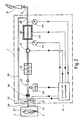
- This heating device 50 preferably constitutes a heat accumulator, and is controlled by the control circuit 10 in response to a control signal representative of the flow rate of the fluid leaving the chamber, that is to say tell about the operating condition of the burner 6.
- the device 50 comprises a sealed envelope 52 containing a heat transfer fluid 54 and in which the catalyst 18 is disposed, this envelope 52 also comprising a heating resistor 56 in direct contact with the heat transfer fluid.
- the resistor 56 can be supplied in a variable manner so that it constitutes additional heating means.
- the catalyst can be easily heated to the desired temperature by simple thermal conduction and can, on the one hand, be maintained at its ideal operating temperature when the burner is not operating, and on the other hand, if necessary directly heat the combustion gases to be purified arriving in the catalyst at the ideal catalysis temperature.
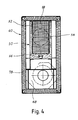
- FIGS. 3 and 4 it can be seen how the variant embodiment of the device of the invention shown in FIG. 2 can be produced practically, the filter 46 and the bypass path 26 having been omitted.
- the device which alone forms a purification unit intended to be put in place on a path for evacuating combustion gases of the conventional type is placed inside a box 60.
- the two branches 70, 72 of the U respectively house the catalyst 18 (in this case two superimposed catalysts) and the injection means 24 formed by the nozzle 74 projecting inside the conduit 68.
- the core 76 of the U connects the parts of the circuit 70, 72 and comprises the blowing means 14 formed by a fan.
- the fan constitutes both the blowing means 12 and the mixing device 14.
- the interior walls of the box 60 comprise a conventional thermally insulating coating 78 of the glass wool type or the like.
Landscapes
- Engineering & Computer Science (AREA)
- Environmental & Geological Engineering (AREA)
- Chemical & Material Sciences (AREA)
- Health & Medical Sciences (AREA)
- Biomedical Technology (AREA)
- Analytical Chemistry (AREA)
- General Chemical & Material Sciences (AREA)
- Oil, Petroleum & Natural Gas (AREA)
- Chemical Kinetics & Catalysis (AREA)
- Treating Waste Gases (AREA)
- Chimneys And Flues (AREA)
- Exhaust Gas Treatment By Means Of Catalyst (AREA)
Applications Claiming Priority (2)
| Application Number | Priority Date | Filing Date | Title |
|---|---|---|---|
| FR8911519 | 1989-09-01 | ||
| FR8911519A FR2651444B1 (fr) | 1989-09-01 | 1989-09-01 | Dispositif pour la reduction de composes d'oxyde d'azote d'un gaz de combustion. |
Publications (2)
| Publication Number | Publication Date |
|---|---|
| EP0415306A1 true EP0415306A1 (de) | 1991-03-06 |
| EP0415306B1 EP0415306B1 (de) | 1994-12-07 |
Family
ID=9385088
Family Applications (1)
| Application Number | Title | Priority Date | Filing Date |
|---|---|---|---|
| EP90116351A Expired - Lifetime EP0415306B1 (de) | 1989-09-01 | 1990-08-27 | Vorrichtung zur Reduktion von Stickoxyden aus Verbrennungsgasen |
Country Status (4)
| Country | Link |
|---|---|
| EP (1) | EP0415306B1 (de) |
| AT (1) | ATE115002T1 (de) |
| DE (1) | DE69014776T2 (de) |
| FR (1) | FR2651444B1 (de) |
Cited By (2)
| Publication number | Priority date | Publication date | Assignee | Title |
|---|---|---|---|---|
| EP0564144A1 (de) * | 1992-04-01 | 1993-10-06 | Uop | Verfahren zum kontrollierten Abbau von N2O in einem N2O-haltigen Gasstrom |
| EP0818232A1 (de) * | 1996-07-08 | 1998-01-14 | The Boc Group, Inc. | Entfernung von Stickstoffoxiden aus Gasströmen |
Citations (5)
| Publication number | Priority date | Publication date | Assignee | Title |
|---|---|---|---|---|
| EP0163001A2 (de) * | 1984-03-02 | 1985-12-04 | Uhde GmbH | Vorrichtung zur Verminderung des NO X-Gehaltes in Abgasen |
| EP0170567A1 (de) * | 1984-07-06 | 1986-02-05 | Seb S.A. | Vorrichtung zur Reinigung der Luft in einem Raum und Vorrichtung zur Heizung oder Behandlung von Luft die eine solche Vorrichtung enthält |
| EP0191441A1 (de) * | 1985-02-15 | 1986-08-20 | Linde Aktiengesellschaft | Vorrichtung zur Entfernung unerwünschter Bestandteile aus einem Rauchgas |
| EP0226203A2 (de) * | 1985-12-20 | 1987-06-24 | Polska Akademia Nauk Instytut Katalizy i Fizykochemii Powierzchni | Verfahren und Vorrichtung zur katalytischen Reinigung von Gasen mit geringem Verunreinigungsgehalt |
| EP0234817A2 (de) * | 1986-02-12 | 1987-09-02 | Babcock-Hitachi Kabushiki Kaisha | Verfahren und Vorrichtung zur Denitrierung |
-
1989
- 1989-09-01 FR FR8911519A patent/FR2651444B1/fr not_active Expired - Fee Related
-
1990
- 1990-08-27 DE DE69014776T patent/DE69014776T2/de not_active Expired - Fee Related
- 1990-08-27 EP EP90116351A patent/EP0415306B1/de not_active Expired - Lifetime
- 1990-08-27 AT AT90116351T patent/ATE115002T1/de not_active IP Right Cessation
Patent Citations (5)
| Publication number | Priority date | Publication date | Assignee | Title |
|---|---|---|---|---|
| EP0163001A2 (de) * | 1984-03-02 | 1985-12-04 | Uhde GmbH | Vorrichtung zur Verminderung des NO X-Gehaltes in Abgasen |
| EP0170567A1 (de) * | 1984-07-06 | 1986-02-05 | Seb S.A. | Vorrichtung zur Reinigung der Luft in einem Raum und Vorrichtung zur Heizung oder Behandlung von Luft die eine solche Vorrichtung enthält |
| EP0191441A1 (de) * | 1985-02-15 | 1986-08-20 | Linde Aktiengesellschaft | Vorrichtung zur Entfernung unerwünschter Bestandteile aus einem Rauchgas |
| EP0226203A2 (de) * | 1985-12-20 | 1987-06-24 | Polska Akademia Nauk Instytut Katalizy i Fizykochemii Powierzchni | Verfahren und Vorrichtung zur katalytischen Reinigung von Gasen mit geringem Verunreinigungsgehalt |
| EP0234817A2 (de) * | 1986-02-12 | 1987-09-02 | Babcock-Hitachi Kabushiki Kaisha | Verfahren und Vorrichtung zur Denitrierung |
Cited By (2)
| Publication number | Priority date | Publication date | Assignee | Title |
|---|---|---|---|---|
| EP0564144A1 (de) * | 1992-04-01 | 1993-10-06 | Uop | Verfahren zum kontrollierten Abbau von N2O in einem N2O-haltigen Gasstrom |
| EP0818232A1 (de) * | 1996-07-08 | 1998-01-14 | The Boc Group, Inc. | Entfernung von Stickstoffoxiden aus Gasströmen |
Also Published As
| Publication number | Publication date |
|---|---|
| EP0415306B1 (de) | 1994-12-07 |
| ATE115002T1 (de) | 1994-12-15 |
| DE69014776T2 (de) | 1995-07-13 |
| FR2651444A1 (fr) | 1991-03-08 |
| FR2651444B1 (fr) | 1993-11-26 |
| DE69014776D1 (de) | 1995-01-19 |
Similar Documents
| Publication | Publication Date | Title |
|---|---|---|
| FR2850704A1 (fr) | Procede de post-injection de gazole pour la regeneration de systemes de filtration des gaz d'echappement de moteur diesel | |
| FR2667134A1 (fr) | Procede d'amelioration de la combustion pour bruleur a air souffle et moyens destines a le mettre en óoeuvre. | |
| FR2504409A1 (fr) | Dispositif de traitement de gaz s'appliquant a plusieurs chaudieres | |
| EP1330597A1 (de) | Reinigungsverfahren der stromaufwärtigen stirnseite eines partikelfilters | |
| FR2966907A1 (fr) | Generateur de vapeur a recuperation de chaleur et regeneration catalytique | |
| FR2771449A1 (fr) | Procede et dispositif de regeneration d'un filtre a particules | |
| FR2743617A1 (fr) | Procede et dispositif d'epuration d'effluents gazeux contenant des substances nocives par combustion et transformation chimique a l'aide d'une flamme dans une chambre de combustion | |
| EP0686686B1 (de) | Ofen zur thermischen Behandlung von Abfällen und Verfahren | |
| EP0938362B1 (de) | Verfahren zur abtrennung von staub aus einem gasstrom | |
| EP0415306B1 (de) | Vorrichtung zur Reduktion von Stickoxyden aus Verbrennungsgasen | |
| EP1072764A1 (de) | Vorrichtung und Verfahren zur Behandlung von Abgasen eines Verbrennungsmotors | |
| FR2721974A1 (fr) | Detecteur d'echappement et procede de detection | |
| EP0495710A2 (de) | Anlage zur Wärmeerzeugung mit Entschwefelungsvorrichtung durch regenerierbare Absorptionsmittel | |
| EP0990848B1 (de) | Verfahren zum thermischen Reinigen von Gasen und regenerative thermische Verbrennungsvorrichtung | |
| EP1223312B1 (de) | Abgasnachbehandlungssystem für einen Verbrennungsmotor und Verfahren zur Regelung eines solchen Systems | |
| WO2002097327A1 (fr) | Generateur thermique et procede de combustion permettant de limiter les emissions d'oxydes d'azote par recombustion des fumees | |
| EP0727253B1 (de) | Verfahren und Vorrichtung zum Regenerieren von Sorbentien, die verwendet werden zur Behandlung von Brennprodukten in Heizkesseln | |
| EP1421267A1 (de) | Verfahren zur regenerierung einer abgasfiltriervorrichtung für dieselmotoren und vorrichtung dafür | |
| EP1672194B1 (de) | Verfahren zur Regeneration eines Partikelfilters mit einer katalytischen Verbrennungseinheit und das Verfahren verwendende Filtervorrichtung | |
| EP1556586B1 (de) | Verfahren und vorrichtung zur regenerierung eines partikelfilters für abgasleitungen, und geeigneter partikelfilter | |
| WO2003093659A1 (fr) | Procede de nettoyage de la face amont d'un filtre a particules | |
| WO2002094415A1 (fr) | Procede de nettoyage de la face amont d'un filtre a particules | |
| FR2756753A1 (fr) | Dispositif rotatif perfectionne d'epuration catalytique d'effluents gazeux | |
| FR2733798A1 (fr) | Procede et dispositif de traitement de gaz de carter par chauffage avec apport reglable d'energie calorifique | |
| FR2827632A1 (fr) | Procede et dispositif de reduction d'emission polluante |
Legal Events
| Date | Code | Title | Description |
|---|---|---|---|
| PUAI | Public reference made under article 153(3) epc to a published international application that has entered the european phase |
Free format text: ORIGINAL CODE: 0009012 |
|
| AK | Designated contracting states |
Kind code of ref document: A1 Designated state(s): AT CH DE DK ES GB GR IT LI NL SE |
|
| 17P | Request for examination filed |
Effective date: 19910702 |
|
| 17Q | First examination report despatched |
Effective date: 19930512 |
|
| GRAA | (expected) grant |
Free format text: ORIGINAL CODE: 0009210 |
|
| AK | Designated contracting states |
Kind code of ref document: B1 Designated state(s): AT CH DE DK ES GB GR IT LI NL SE |
|
| PG25 | Lapsed in a contracting state [announced via postgrant information from national office to epo] |
Ref country code: IT Free format text: LAPSE BECAUSE OF FAILURE TO SUBMIT A TRANSLATION OF THE DESCRIPTION OR TO PAY THE FEE WITHIN THE PRESCRIBED TIME-LIMIT;WARNING: LAPSES OF ITALIAN PATENTS WITH EFFECTIVE DATE BEFORE 2007 MAY HAVE OCCURRED AT ANY TIME BEFORE 2007. THE CORRECT EFFECTIVE DATE MAY BE DIFFERENT FROM THE ONE RECORDED. Effective date: 19941207 Ref country code: AT Effective date: 19941207 Ref country code: ES Free format text: THE PATENT HAS BEEN ANNULLED BY A DECISION OF A NATIONAL AUTHORITY Effective date: 19941207 Ref country code: DK Effective date: 19941207 Ref country code: NL Effective date: 19941207 Ref country code: GB Effective date: 19941207 Ref country code: GR Free format text: LAPSE BECAUSE OF FAILURE TO SUBMIT A TRANSLATION OF THE DESCRIPTION OR TO PAY THE FEE WITHIN THE PRESCRIBED TIME-LIMIT Effective date: 19941207 |
|
| REF | Corresponds to: |
Ref document number: 115002 Country of ref document: AT Date of ref document: 19941215 Kind code of ref document: T |
|
| REF | Corresponds to: |
Ref document number: 69014776 Country of ref document: DE Date of ref document: 19950119 |
|
| PG25 | Lapsed in a contracting state [announced via postgrant information from national office to epo] |
Ref country code: SE Effective date: 19950307 |
|
| NLV1 | Nl: lapsed or annulled due to failure to fulfill the requirements of art. 29p and 29m of the patents act | ||
| GBV | Gb: ep patent (uk) treated as always having been void in accordance with gb section 77(7)/1977 [no translation filed] |
Effective date: 19941207 |
|
| PLBE | No opposition filed within time limit |
Free format text: ORIGINAL CODE: 0009261 |
|
| STAA | Information on the status of an ep patent application or granted ep patent |
Free format text: STATUS: NO OPPOSITION FILED WITHIN TIME LIMIT |
|
| 26N | No opposition filed | ||
| REG | Reference to a national code |
Ref country code: CH Ref legal event code: NV Representative=s name: ICB INGENIEURS CONSEILS EN BREVETS SA |
|
| PGFP | Annual fee paid to national office [announced via postgrant information from national office to epo] |
Ref country code: CH Payment date: 20020729 Year of fee payment: 13 |
|
| PGFP | Annual fee paid to national office [announced via postgrant information from national office to epo] |
Ref country code: DE Payment date: 20020805 Year of fee payment: 13 |
|
| PG25 | Lapsed in a contracting state [announced via postgrant information from national office to epo] |
Ref country code: CH Free format text: LAPSE BECAUSE OF NON-PAYMENT OF DUE FEES Effective date: 20030831 Ref country code: LI Free format text: LAPSE BECAUSE OF NON-PAYMENT OF DUE FEES Effective date: 20030831 |
|
| PG25 | Lapsed in a contracting state [announced via postgrant information from national office to epo] |
Ref country code: DE Free format text: LAPSE BECAUSE OF NON-PAYMENT OF DUE FEES Effective date: 20040302 |
|
| REG | Reference to a national code |
Ref country code: CH Ref legal event code: PL |