EP0415308A2 - Système de freinage de type courants de Foucault - Google Patents
Système de freinage de type courants de Foucault Download PDFInfo
- Publication number
- EP0415308A2 EP0415308A2 EP90116360A EP90116360A EP0415308A2 EP 0415308 A2 EP0415308 A2 EP 0415308A2 EP 90116360 A EP90116360 A EP 90116360A EP 90116360 A EP90116360 A EP 90116360A EP 0415308 A2 EP0415308 A2 EP 0415308A2
- Authority
- EP
- European Patent Office
- Prior art keywords
- rotor
- brake system
- permanent magnets
- eddy current
- casing
- Prior art date
- Legal status (The legal status is an assumption and is not a legal conclusion. Google has not performed a legal analysis and makes no representation as to the accuracy of the status listed.)
- Granted
Links
Images

Classifications
-
- H—ELECTRICITY
- H02—GENERATION; CONVERSION OR DISTRIBUTION OF ELECTRIC POWER
- H02K—DYNAMO-ELECTRIC MACHINES
- H02K49/00—Dynamo-electric clutches; Dynamo-electric brakes
- H02K49/02—Dynamo-electric clutches; Dynamo-electric brakes of the asynchronous induction type
- H02K49/04—Dynamo-electric clutches; Dynamo-electric brakes of the asynchronous induction type of the eddy-current hysteresis type
- H02K49/043—Dynamo-electric clutches; Dynamo-electric brakes of the asynchronous induction type of the eddy-current hysteresis type with a radial airgap
-
- B—PERFORMING OPERATIONS; TRANSPORTING
- B60—VEHICLES IN GENERAL
- B60T—VEHICLE BRAKE CONTROL SYSTEMS OR PARTS THEREOF; BRAKE CONTROL SYSTEMS OR PARTS THEREOF, IN GENERAL; ARRANGEMENT OF BRAKING ELEMENTS ON VEHICLES IN GENERAL; PORTABLE DEVICES FOR PREVENTING UNWANTED MOVEMENT OF VEHICLES; VEHICLE MODIFICATIONS TO FACILITATE COOLING OF BRAKES
- B60T8/00—Arrangements for adjusting wheel-braking force to meet varying vehicular or ground-surface conditions, e.g. limiting or varying distribution of braking force
- B60T8/32—Arrangements for adjusting wheel-braking force to meet varying vehicular or ground-surface conditions, e.g. limiting or varying distribution of braking force responsive to a speed condition, e.g. acceleration or deceleration
- B60T8/72—Arrangements for adjusting wheel-braking force to meet varying vehicular or ground-surface conditions, e.g. limiting or varying distribution of braking force responsive to a speed condition, e.g. acceleration or deceleration responsive to a difference between a speed condition, e.g. deceleration, and a fixed reference
Definitions
- the present invention relates to an eddy current type brake system for a vehicle, and more particularly to an eddy current type brake system which allows a rotor to produce an eddy current by use of permanent magnets.
- an eddy current type brake system is known as a retarder which applies a steady brake force to a vehicle so as to control a deceleration of the vehicle during a long down slope driving and prevent a foot brake (main brake) from burning.
- the eddy current type brake system comprises a rotor mounted on a rotative shaft (for example, a propeller shaft) drivingly connected with wheels of the vehicle, and a magnet source including an electoromagnet and a permanent magnet on a body frame of the vehicle.
- a difference in relative speed between the magnet source on the body frame (stationary member) and the rotor on the rotative shaft (rotary member) allows the rotor to produce an eddy current which applies the brake force to its rotation so as to decelerate the vehicle.
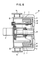
- Figure 6 shows a conventional eddy current type brake system (a) using a permanent magnet as the magnet source.
- a cylindrical, drum-like rotor (c) is fit on one end of a rotating shaft (b).
- Permanent magnets (d) are located inside the drum and supported by the body frame (not shown) (stationary member) of the vehicle in a manner such that the permanent magnets (d) can move between a position at which the permanent magnets (d) face the rotor (c) entirely and another position at which they do not face the rotor (c) entirely.
- the rotor (c) is formed from materials having conductive and magnetic characteristics, for example, Fe material.
- the permanent magnets (d) are formed from rare earth elements such as neodymium to provide strong magnetic force.
- a ring member (e) is provided inside the rotor (c).
- the ring member (e) is a cylindrical member having a mutual center axis with the rotor (c) and having a diameter smaller than the rotor (c).
- the pemanent magnets (d) are installed on the support ring (e) circumferentially with their S poles and N poles being arranged alternately and with the S pole of one magnet (d) being positioned closed to the N pole of the adjacent magnet (d).
- the support ring (e) is moved in the axial direction of the rotating shaft (b) by means of a motor (f) to have the permanent magnets (d) opposed fully to the rotor (c) (right in the drawing), a plurality of magnetic circuits are formed between the rotor (c) and the permanent magnets (d).
- Each magnetic circuit magentically connects the N pole of one magnet (d), the rotor (c), the S pole of an adjacent magnet (d), the N pole of the same magnet (d) and the above-mentioned one magnet (d).
- a difference in relative speed between the rotating rotor (c) and the permanent magnets on the fixed side produces an eddy current to brake the rotor (c) whereby the rotation of the rotor (c) is decelerated and the rotating shaft (b) eventually stops.
- the permanent magnets (d) are entirely moved from the rotor (c)
- the rotor (c) is released from the brake force or the brake force against the rotor (c) is not produced any more.
- a cylindrical element (g) having the same diameter as the rotor (c) is mounted on a free end of the rotor (c), as shown in Figure 6.
- the cylindrical element (g) is supported on the body frame of the vehicle via extensions (h) so that the cylindrical element (g) is separated from the rotor (c).
- the cylindrical element (g) forms a casing 1 for the permanent magnet (d) together with the rotor (c).
- the casing (i) which covers the permanent magnets (d) is made from the rotative rotor (c) and the stationary cylindrical element (g), which means that they are slidable relative to each other, and therefore moisture and dust may reach the permanent magnets (d) through a small clearance (j) between the rotor (c) and the cylindrical element (g).
- the permanent magnets (d) when the permanent magnets (d) are fully opposed to the rotor (c) to apply the brake force to the rotating shaft (b), the permanent magnets (d) may suffer directly heat of the rotor (c) heated by the eddy current generated. This might result in heat deterioration of the brake system.
- the permanent magnets (d) are formed from the rare earth metal, the deteriorations caused by moisture, dust, and heat appear more seriously.
- An object of the present invention is to prevent the deteriorations of the magnetism of the magnets which are caused by the moisture, dust and heat.
- an eddy current type brake system for a vehicle comprising a rotor mounted on a rotative shaft of an engine of the vehicle, permanent magnets which apply a brake to the rotative shaft by approaching the rotor and release the applied brake by leaving the rotor, and a casing provided between the rotor and the permanent magnets for sealingly covering the permanent magnets in a manner such that the permanent magnets can approach and leave the rotor.
- the casing since the casing seals the permanent magnets, moisture and duct do not reach the permanent magnets. Also, since the casing extends between the rotor and the permanent magnets, the influence of the heat produced by the eddy current is weakened by the casing, with respect to the permanent magnets.
- a flange 2 is formed on an output shaft 1 of a transmission of a vehicle.
- the flange 2 extends in the radial direction of the shaft 1.
- a brake drum 3 for a parking brake and a drum type rotor 4 of an eddy current type brake system are mounted on the flange 2 together with a bolt 5.
- the rotor 4 is formed into cylindrical shape and has a base.
- the rotor 4 is made from conductive and magnetic materials.
- Permanent magnets 6 are located inside of the drum-shaped rotor 4 and supported by a transmission casing (not shown) in a manner such that the permanent magnets 6 can move in an axial direction of the rotor 4. specifically, the magents 6 can approach and leave the rotor 4.
- Cooling fins y are formed on an outer wall of the drum
- the permanent magnets 6 are formed from rare earth elements such as neodymium providing strong magnetic force, and compact in size and light in weight, And even number of pieces (about 8-12) of permanent magnets are located circumferentially on a support ring 8 at given intervals with their S and N poles being reversed alternately.
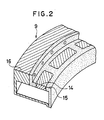
- the permanent magnets 6 and the support ring 8 on which the permanent magnets are provided circumferentially are sealed by a casing 9.
- the casing 9 allows the permanent magnets 6 to approach and leave the rotor 4.
- the case 9 is located inside the rotor 4 with a predetermined clearance being maintained therebetween.
- An actuator 10 is attached on the casing 9 to move the permanent magnets 6 in the vicinity of the rotor 4 and to move the permanent magnets 6 far from rotor 4.
- the actuator 10 includes a hollow cylinder 11, a piston 12 movably provided in the cylinder 11 and a push rod 13 connecting the support ring 8 with the piston 12. High presure air is charged in and discharged out of the cylinder 11 to operate the piston 12, the permanent magnets 6 on the support ring 8 moved right and left in the drawing via the push rod 13.
- the casing 9 tightly encloses the permanent magnets 6 and the supporting ring 8.
- the casing 9 is formed partially from a ferro-magnetic material with high permeability and partially from a non-magnetic material with low Permeability.
- that part 14 of the casing 9 ("pole piece" 14) which faces the permanent magnets 6 when the support ring 8 comes to the rightmost position (braking position) as indicate by the solid line in the drawing is made from a low-carbon iron, which is close to a pure iron, for example from a ferro-magnetic material such as a ferrite iron
- parts 15 next to the ferromagnetic part 14 is made from a non-magnetic material such as aluminum
- that part 16 which faces the permanent magnets when the support ring 8 comes to the leftmost position (brake releasing position) as indicated by the dashed line is maded from low-carbon iron, for example from a ferro-magnetic material such as ferrite, like the pole piece 14.
- the casing 9 includes the ferro-magnetic parts 14 and 16 as indicated by the oblique lines and the non-magnetic part 15 as indicated by the dots.
- the part 14 includes a plurality of pole pieces which respectively face a plurality of permanent magnets 6 on the support ring 8 when the support ring 8 is moved in the braking position.
- one pole piece 14 makes a pair with one permanent magnet 6 when the support ring 8 comes to the braking Position.
- the ferro-magnetic part 14 is discontinuous in the circumferential direction of the support ring 8.
- the other ferro-magnetic part 16 is a one piece element and continuous in the circumferential direction of the support ring 8.
- the ferro-magnetic part 16 and the non-magnetic material 15 are tightly joined with each other with screws.
- the part 14 and 15 are also tightly joined with each other by a proper engagement or a sealing agent.
- the tight joint is possible since all the members 14, 15 and 16 are stationary members. If one of them is a rotative member, like the conventional arrangement, the tight joint is practically impossible.
- the structure of the embodiment according to the present invention allows the casing 9 to shut out external moisture and dusts. This cannot be attained by the conventional structure.
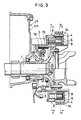
- Figure 3 illustrates an overall sectional view of the eddy current type brake system having a structure explained above.
- the rotor 4 of the eddy current type retarder and the brake drum 3 for the parking brake are mounted on the output shaft 1 at a rear element 171 of a transmission housing 17, and the magn et casing 9 is mounted on the tramsmission casing 17 with the extension 18.
- Numeral 19 designates brake shoes of the parking brake.
- the support ring 8 is moved to the braking position by the actuator 10 so that the permanent magnets 6 entirely face the pole pieces 14.
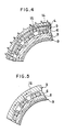
- a magnet circuit extending through the N pole of one magnet 6, the ferromagnetic part 14, the rotor 4, the adjacent ferromagnetic part 14, the S Pole of the adjacent magnet 6, the N pole of the same magent 6, the support ring 8, the S pole of the above-mentioned one magnet 6 and the N pole of the same magnet 6, as shown in Figure 4. From another point of view, it can be said that a magnetic circuit encircling the non-magnetic part 15 is formed because the non-magnetic part 15 allows the magnetic circuit to extend into the rotor 4. The eddy current flows in the magnetic circuit and the brake force is applied to the rotor 4.
- the supporting ring 8 is moved away from the rotor 4 by the acutator 10 as indicated by the dashed line in Figure 3 and the permanent magnets 6 are located under the other ferromagnetic part 16, as shown in Figure 5.
- the magnetic circuit does not reach the rotor 4 but extends through the N pole of one magent 6, the ferromagnetic part 16 of the casing 15, the S pole of the next magnet 6, the N pole of the same magnet 6, the support ring 8, the S pole of the above-mentioned one magnet 6 and the N pole of the same magnet. Therefore, the magnetic circuit does not penetrate the rotor 4.
- the rotor 4 becomes hot as the eddy current flows in the rotor 4.
- a considerable amount of heat of the rotor 4 is absorbed by the casing 9 located between the rotor 4 and the permanent magnets 6 so that the influence of the heat of the rotor 4, on the permanent magnets 6 is small.
- there is a clearance between the rotor 4 and the casing 9 so that air in the clearance serves as the heat insulator, too.
- the casing 9 protects the permanent magnets 6 from dusts, moisture and heat so that the permanent magnets 6 can continuously exhibit their ferromagnetic characteristic.
Landscapes
- Engineering & Computer Science (AREA)
- Power Engineering (AREA)
- Transportation (AREA)
- Mechanical Engineering (AREA)
- Dynamo-Electric Clutches, Dynamo-Electric Brakes (AREA)
- Electric Propulsion And Braking For Vehicles (AREA)
- Braking Arrangements (AREA)
Applications Claiming Priority (2)
| Application Number | Priority Date | Filing Date | Title |
|---|---|---|---|
| JP1218499A JPH0614782B2 (ja) | 1989-08-28 | 1989-08-28 | 渦電流式減速装置 |
| JP218499/89 | 1989-08-28 |
Publications (3)
| Publication Number | Publication Date |
|---|---|
| EP0415308A2 true EP0415308A2 (fr) | 1991-03-06 |
| EP0415308A3 EP0415308A3 (en) | 1992-04-01 |
| EP0415308B1 EP0415308B1 (fr) | 1994-01-12 |
Family
ID=16720891
Family Applications (1)
| Application Number | Title | Priority Date | Filing Date |
|---|---|---|---|
| EP90116360A Expired - Lifetime EP0415308B1 (fr) | 1989-08-28 | 1990-08-27 | Système de freinage de type courants de Foucault |
Country Status (4)
| Country | Link |
|---|---|
| EP (1) | EP0415308B1 (fr) |
| JP (1) | JPH0614782B2 (fr) |
| KR (1) | KR910004406A (fr) |
| DE (1) | DE69005948T2 (fr) |
Cited By (5)
| Publication number | Priority date | Publication date | Assignee | Title |
|---|---|---|---|---|
| EP0777316A1 (fr) * | 1995-11-30 | 1997-06-04 | Isuzu Motors Limited | Ralentisseur à courant de Foucault du type à aimants permanents |
| US6039157A (en) * | 1997-02-25 | 2000-03-21 | Isuzu Motors Limited | Eddy current braking system |
| EP1005144A1 (fr) * | 1997-06-12 | 2000-05-31 | Isuzu Motors Limited | Ralentisseur à courant de Foucault du type à aimants permanents |
| EP3264576A4 (fr) * | 2015-02-24 | 2018-10-17 | Nippon Steel & Sumitomo Metal Corporation | Élément chauffant à courant de foucault |
| WO2020122850A1 (fr) * | 2018-12-12 | 2020-06-18 | Ondokuz Mayis Üni̇versi̇tesi̇ Rektörlük | Système réducteur hybride |
Families Citing this family (2)
| Publication number | Priority date | Publication date | Assignee | Title |
|---|---|---|---|---|
| DE102022207183A1 (de) * | 2022-07-14 | 2024-01-25 | Robert Bosch Gesellschaft mit beschränkter Haftung | Elektrische Maschine mit einer Wirbelstrombremse |
| NL2038386B1 (en) * | 2024-08-02 | 2026-02-19 | A F J Farla Beheer B V | Lighting device for lifting apparatus comprising eddy current induced damping mechanism |
Family Cites Families (3)
| Publication number | Priority date | Publication date | Assignee | Title |
|---|---|---|---|---|
| JPS5011007B1 (fr) * | 1968-07-01 | 1975-04-26 | ||
| FR2514966B1 (fr) * | 1981-10-16 | 1987-04-24 | Materiel Magnetique | Convertisseur d'energie cinetique de rotation en chaleur par generation de courants de foucault |
| US4853573A (en) * | 1988-07-29 | 1989-08-01 | Eaton Corporation | Eddy current brake assembly |
-
1989
- 1989-08-28 JP JP1218499A patent/JPH0614782B2/ja not_active Expired - Lifetime
-
1990
- 1990-08-27 KR KR1019900013198A patent/KR910004406A/ko not_active Withdrawn
- 1990-08-27 DE DE69005948T patent/DE69005948T2/de not_active Expired - Lifetime
- 1990-08-27 EP EP90116360A patent/EP0415308B1/fr not_active Expired - Lifetime
Cited By (5)
| Publication number | Priority date | Publication date | Assignee | Title |
|---|---|---|---|---|
| EP0777316A1 (fr) * | 1995-11-30 | 1997-06-04 | Isuzu Motors Limited | Ralentisseur à courant de Foucault du type à aimants permanents |
| US6039157A (en) * | 1997-02-25 | 2000-03-21 | Isuzu Motors Limited | Eddy current braking system |
| EP1005144A1 (fr) * | 1997-06-12 | 2000-05-31 | Isuzu Motors Limited | Ralentisseur à courant de Foucault du type à aimants permanents |
| EP3264576A4 (fr) * | 2015-02-24 | 2018-10-17 | Nippon Steel & Sumitomo Metal Corporation | Élément chauffant à courant de foucault |
| WO2020122850A1 (fr) * | 2018-12-12 | 2020-06-18 | Ondokuz Mayis Üni̇versi̇tesi̇ Rektörlük | Système réducteur hybride |
Also Published As
| Publication number | Publication date |
|---|---|
| DE69005948D1 (de) | 1994-02-24 |
| DE69005948T2 (de) | 1994-05-19 |
| KR910004406A (ko) | 1991-03-28 |
| EP0415308A3 (en) | 1992-04-01 |
| JPH0386061A (ja) | 1991-04-11 |
| EP0415308B1 (fr) | 1994-01-12 |
| JPH0614782B2 (ja) | 1994-02-23 |
Similar Documents
| Publication | Publication Date | Title |
|---|---|---|
| US5145038A (en) | Eddy current type retarder | |
| US5023499A (en) | Eddy current type brake system | |
| US5154623A (en) | Eddy current type brake system | |
| US5064029A (en) | Eddy current retarder | |
| EP0566745B1 (fr) | Ralentisseur du type a courants de foucault | |
| US5804897A (en) | Permanent magnet vehicle braking apparatus | |
| US6237728B1 (en) | Eddy current reduction braking system | |
| EP0415308B1 (fr) | Système de freinage de type courants de Foucault | |
| US6220403B1 (en) | Eddy current braking system | |
| US5143183A (en) | Eddy current braking system | |
| JP2701084B2 (ja) | 渦電流式減速装置 | |
| JPH0747989Y2 (ja) | 渦電流式減速装置の磁気シールドケーシング | |
| JP3285043B2 (ja) | 渦電流式減速装置 | |
| JP2601177Y2 (ja) | 渦電流式リターダのポールピース構造 | |
| JPH0746065Y2 (ja) | 渦電流式リターダ | |
| JP2000350436A (ja) | 渦電流式減速装置 | |
| JPH0469046A (ja) | 渦電流式減速装置 | |
| JPH0421352A (ja) | 渦電流式減速装置 | |
| JPH0811053Y2 (ja) | 渦電流式リターダ | |
| JPH0759145B2 (ja) | 渦電流式リターダ | |
| JP2004343955A (ja) | 渦電流式減速装置 | |
| JP2000358354A (ja) | 渦電流式減速装置 | |
| JPH04289761A (ja) | 渦電流式減速装置 | |
| JP2005094878A (ja) | 渦電流式減速装置 | |
| JPH05176524A (ja) | 渦電流式減速装置 |
Legal Events
| Date | Code | Title | Description |
|---|---|---|---|
| PUAI | Public reference made under article 153(3) epc to a published international application that has entered the european phase |
Free format text: ORIGINAL CODE: 0009012 |
|
| AK | Designated contracting states |
Kind code of ref document: A2 Designated state(s): DE FR GB |
|
| PUAL | Search report despatched |
Free format text: ORIGINAL CODE: 0009013 |
|
| AK | Designated contracting states |
Kind code of ref document: A3 Designated state(s): DE FR GB |
|
| 17P | Request for examination filed |
Effective date: 19920824 |
|
| 17Q | First examination report despatched |
Effective date: 19930519 |
|
| GRAA | (expected) grant |
Free format text: ORIGINAL CODE: 0009210 |
|
| AK | Designated contracting states |
Kind code of ref document: B1 Designated state(s): DE FR GB |
|
| REF | Corresponds to: |
Ref document number: 69005948 Country of ref document: DE Date of ref document: 19940224 |
|
| ET | Fr: translation filed | ||
| PLBE | No opposition filed within time limit |
Free format text: ORIGINAL CODE: 0009261 |
|
| STAA | Information on the status of an ep patent application or granted ep patent |
Free format text: STATUS: NO OPPOSITION FILED WITHIN TIME LIMIT |
|
| 26N | No opposition filed | ||
| REG | Reference to a national code |
Ref country code: GB Ref legal event code: IF02 |
|
| PGFP | Annual fee paid to national office [announced via postgrant information from national office to epo] |
Ref country code: FR Payment date: 20090814 Year of fee payment: 20 |
|
| PGFP | Annual fee paid to national office [announced via postgrant information from national office to epo] |
Ref country code: DE Payment date: 20090821 Year of fee payment: 20 Ref country code: GB Payment date: 20090826 Year of fee payment: 20 |
|
| REG | Reference to a national code |
Ref country code: GB Ref legal event code: PE20 Expiry date: 20100826 |
|
| PG25 | Lapsed in a contracting state [announced via postgrant information from national office to epo] |
Ref country code: GB Free format text: LAPSE BECAUSE OF EXPIRATION OF PROTECTION Effective date: 20100826 |
|
| PG25 | Lapsed in a contracting state [announced via postgrant information from national office to epo] |
Ref country code: DE Free format text: LAPSE BECAUSE OF EXPIRATION OF PROTECTION Effective date: 20100827 |