EP0415722A2 - Abbildungsgerät - Google Patents
Abbildungsgerät Download PDFInfo
- Publication number
- EP0415722A2 EP0415722A2 EP90309412A EP90309412A EP0415722A2 EP 0415722 A2 EP0415722 A2 EP 0415722A2 EP 90309412 A EP90309412 A EP 90309412A EP 90309412 A EP90309412 A EP 90309412A EP 0415722 A2 EP0415722 A2 EP 0415722A2
- Authority
- EP
- European Patent Office
- Prior art keywords
- density
- original
- character
- forming apparatus
- image
- Prior art date
- Legal status (The legal status is an assumption and is not a legal conclusion. Google has not performed a legal analysis and makes no representation as to the accuracy of the status listed.)
- Granted
Links
Images



Classifications
-
- H—ELECTRICITY
- H04—ELECTRIC COMMUNICATION TECHNIQUE
- H04N—PICTORIAL COMMUNICATION, e.g. TELEVISION
- H04N1/00—Scanning, transmission or reproduction of documents or the like, e.g. facsimile transmission; Details thereof
- H04N1/40—Picture signal circuits
- H04N1/407—Control or modification of tonal gradation or of extreme levels, e.g. background level
- H04N1/4072—Control or modification of tonal gradation or of extreme levels, e.g. background level dependent on the contents of the original
-
- H—ELECTRICITY
- H04—ELECTRIC COMMUNICATION TECHNIQUE
- H04N—PICTORIAL COMMUNICATION, e.g. TELEVISION
- H04N1/00—Scanning, transmission or reproduction of documents or the like, e.g. facsimile transmission; Details thereof
- H04N1/40—Picture signal circuits
- H04N1/40062—Discrimination between different image types, e.g. two-tone, continuous tone
Definitions
- the present invention relates to an image forming apparatus such as an electrophotographic copying machine, facsimile, printer and the like, and more particularly, it relates to an image forming apparatus for reproducing an original having an image including a character portion and an intermediate contrast portion such as photograph, picture and the like.
- any original to be read includes an image having, for example, both a character portion and a photograph portion
- the simple density conversion results in the unproper density output. That is to say, with respect to the image of the original including both the character portion and the photograph portion, when the same or similar density conversion is effected regarding the character portion and the photograph portion, even if the reproduction of intermediate contrast of the photograph portion is important, such photograph portion is subjected to the large or heavy density conversion, with the result that the gradient of contrast is deteriorated, thus making the reproduction of the image having the intermediate contrast impossible.
- This problem can be solved by discriminating the character portion from the photograph portion by using an editor having the function for designating the image areas on the original with the image forming apparatus.
- problems that the manipulation of the editor is troublesome and that the apparatus becomes expensive due to the addition of the editor.
- An object of the present invention is to obtain a faithful reproduction image from an original image including both a character portion and an intermediate contrast portion such as a photograph.
- Another object of the present invention is to automatically obtain a sharp image with retaining density-light of an original even if an image of the original has different density distribution, by performing the density conversion required to reproduce the character with respect to a character portion and by performing the density conversion required to reproduce the photograph with respect to a photograph portion on the basis of the data obtained from the automatic discrimination between the character portion and the photograph portion.
- the present invention provides an image forming apparatus for forming a reproduction image from an original, comprising an original density detecting means for detecting maximum density and minimum density of the original; a calculating means for obtaining density converting tables for intermediate contrast on the basis of the detection result regarding the maximum density and the minimum density from the detecting means; and a discriminating means for discriminating a character portion and an intermediate contrast portion of the original.
- the original includes both the character portion and the intermediate contrast portion
- the density converting table for character portion is applied to the character portion and the density converting table for intermediate contrast portion is applied to the intermediate contrast portion.
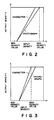
- the present invention is directed to obtain a sharp image having different density-light areas regarding a background portion, character portion and photograph portion of an original, by detecting the maximum density and the minimum density of the original and by performing the different density conversions regarding the character portion and the photograph portion, for example, as shown in Fig. 2.
- the original has a light character portion or a photograph portion (for example, the original consists of a graph sheet), it is possible to remove the fog of the original background and to control the image quality not to make the character portion or the photograph portion dense excessively.
- a light character portion or a photograph portion for example, the original consists of a graph sheet
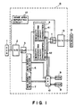
- Fig. 1 shows a block diagram of a copying machine according to an embodiment of the present invention.
- a processing portion shown by a square broken line 15 performs the signal processing for the density conversion.
- An original inputting portion 1 is constituted by a so-called CCD linear sensor which inputs the density of the original.
- An inputted analogue signal is converted into a digital signal by means of an A/D converter 2.
- a bus switch 3 is controlled by a CPU (central processing unit) 8 to select whether the digital signal of the original is inputted to a density converting circuit 4 or whether the digital signal is inputted to a minimum density detector 6 and a maximum density detector 7.
- the minimum density detector 6 detects the minimum density of the density data included in one line in a main scanning direction of the CCD, and sends the detected result to the CPU 8.
- the maximum density detector 7 detects the maximum of the density data included in one line, and sends the detected result to the CPU 8.
- Density converting circuits 41 and 42 perform the density converting operation on the basis of the density converting coefficiency set by the CPU 8. The calculation of the density converting coefficiency will be described later.
- a read only memory (ROM) 9 stores the processing sequence for the CPU 8.
- Two kinds of density converting tables made by the CPU 8 are stored in a random access memory (RAM) 10.
- An image area separating circuit 12 is designed to discriminate whether a present pixel in question in one line read by the CPU 8 is a character pixel or a photograph pixel, and to send character/photograph switching signal to a switch 11.
- the switch 11 connects the character density converting circuit 41 to a D/A converter 13 if the signal corresponds to the character signal, and connects the photograph density converting circuit 42 to the D/A converter 13 if the signal corresponds to the photograph signal.
- the D/A converter 13 converts the digital signal density-converted by the density converting circuit 41 or 42 into an analogue signal.
- a printer 14 is an image outputting device having the expressing ability for density-light gradient and outputs an image signal converted by the processing portion 15.
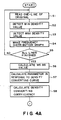
- a step S1 the density of the original in one line in the main scanning direction of the CCD from the original inputting portion 1 is read.
- the minimum density of one line is detected by the minimum density detector 6 and the detected result is sent to the CPU 8.
- the maximum density of one line is detected by the maximum density detector 7 and the detected result is sent to the CPU 8.
- a step S4 the CPU 8 makes or produces frequency distribution graphs (Figs. 6 and 7) of the minimum density value and of the maximum density value sent from the steps S2 and S3, respectively.
- the CPU 8 calculates a minimum density reference value (WS) and a maximum density reference value (BS) from Figs. 6 and 7 in a step S6.
- the minimum density reference value (WS) is obtained as a density value having the maximum frequency of the frequency distribution graph of Fig. 6 regarding the one-line minimum density value
- the maximum density reference value (BS) is obtained as a density value having the maximum frequency of the frequency distribution graph of Fig. 7 regarding the one-line maximum density value.
- the CPU 8 calculates the density converting coefficiency applied to the character portion and the density converting coefficiency applied to the photograph portion, respectively.
- a value (BS - WS) is calculated in a step S71.
- steps S73 and S74 are executed, whereas, if the value is smaller than the predetermined value (i.e., if the difference in density between the original background and the character portion or the photograph portion is small), steps S75 and S76 are executed.
- the steps S73 or S75 supposes the density converting curves for the character portion, and the steps S74 or S76 supposes the density converting curve for the photograph portion.
- the density converting curves are supposed in accordance with the features of the respective images.
- Fig. 8 the feature of the image, the preferable reproduction character required according to such character, and the density converting curve supposed in this embodiment to carry out such reproduction are shown.
- step S73 since the value (BS - WS) is greater than the predetermined value (step S71, i.e., since the density converting curve in the character portion of the image of relatively large contrast is supposed, the reproduction character required is such that "the fog of the original background is completely removed and the character is emphasized". Accordingly, as shown in Fig. 8, it is seen that the above requirement is met by selecting a value of the input density of (WS + b) as a minimum value of the output density and by selecting a value of the input density of (BS - c) as a maximum value of the output density and by supposing the density converting curve obtained by connecting between the minimum and maximum values with respect to the gradient between the minimum and maximum values.
- the reproduction character required is such that "the fog of the original background is completely removed and the reproduction is effected with retaining the density-light of photograph”. Accordingly, as shown in Fig. 8, it is seen that the above requirement is met by selecting a value of the input density of (WS + b) as a minumum value of the output density and by selecting a value of the input density of BS as a maximum value of the output density and by supposing the density converting curve obtained by connecting between the minimum and maximum values with respect to the gradient between the minimum and maximum values.
- the reproduction character required is such that "the fog of the original background is completely removed and the light character is not excessively emphasized". Accordingly, as shown in Fig. 8, it is seen that the above requirement is met by selecting a value of the input density of (WS + b) as a minimum value of the output density and by selecting a value of the input density of BS as a maximum value of the output density and by supposing the density converting curve obtained by connecting between the minimum and maximum values with respect to the gradient between the minimum and maximum values.
- the density converting curve in the photograph portion of the image of small contrast is supposed, the reproduction character required is such that "the fog of the original background is completely removed and the difference of density-light is not excessively emphasized". Accordingly, as shown in Fig. 8, it is seen that the above requirement is met by selecting a value of the input density of (WS + b) as a minimum value of the output density and by selecting a value of the input density of (BS + d) as a maximum value of the output density and by supposing the density converting curve obtained by connecting between the minimum and maximum values with respect to the gradient between the minimum and maximum values.
- the inclination in the curves shown in Fig. 8 are prevented from reversing. Since the above-mentioned density converting curves can be expressed by the information of two points connected by the straight line, in the steps S73 - S76, the variables WSt, BSt, WSp and BSp are calculated on the basis of Fig. 5, these variables being sent to step S81 and S82 as parameters.
- the contents to be treated are the same, but the parameters used are different.
- the density converting table for character is made by using the variables WSt and BSt
- the density converting table for photograph is made by using the variables WSp and BSp.
- the density converting tables (T(n)) are constituted by density converting table data of 256 bits for character and density converting table data of 256 bits for photograph, these tables being designated as Tt(n) and Tp(n), respectively.
- 0th address ⁇ WSp address in the density converting table Tp(n) are occupied by zero (0).
- (BSP + 1) address ⁇ 255th address in the density converting table Tp(n) are occupied by 255.
- the values obtained by linear-interpolating between 0 and 255 are set.
- the density converting tables are calculated by the CPU 8 and are stored in the RAM 10.
- the CPU 8 sets the density converting coefficiency for character to the density converting circuit 41 and sets the density converting coefficiency for photograph to the density converting circuit 42.
- the density converting circuits 41, 42 can convert the input density of 256 gradients into the output density of 256 gradients on the basis of the look-up table shown in Fig. 10.
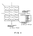
- a step S11 an image area separating treatment for separating the character portion and the photograph portion in the image is effected. This is achieved by discriminating whether the present pixel in question is a character pixel or is a photograph pixel. Such discrimination can be performed by using the following method.
- the image area separating circuit 12 has a plurality of buffers corresponding to few lines of CCD, where the data are stocked.
- vertical, lateral and oblique density differences (inclinations) of the present pixel in question are sought. If the inclinations are greater than a predetermined value, it is considered that such pixel is a vertical, lateral or oblique edge of the character. And, if the pixels are continuous in the vertical, lateral or oblique direction of the present pixel in question, is assumed or considered that the pixel is the character pixel.
- step S12 the sequence goes to a step S13. That is to say, the image area separating circuit 12 sends a signal to the switch 11 to connect the D/A converter 13 to the density converting circuit 41 for character. If it is not judged that the pixel is not the character pixel, the sequence goes from the step S12 to a step S14. That is to say, the image area separating circuit 12 sends a signal to the switch 11 to connect the D/A conveter 13 to the density converting circuit 42 for photograph.
- the density converting curve for character becomes a solid line in Fig. 12, so that the character portion cannot be emphasized adequately. Even if such case occurs, such disadvantage is eliminated by selecting the density converting curve for character as a curve having an upward convex shown a broken line in Fig. 12 rather than the straight line as previous embodiment.
- the density converting curve for character in order to calculate the density converting coefficiency in the step S81, since two or more calculating equations must be used, the calculation becomes complex.
- the density conversion required to reproduce the character is effected regarding the character portion and density conversion required to reproduce the photograph is effected regarding the photograph portion, by automatically discriminating the characger and photograph portions.
Landscapes
- Engineering & Computer Science (AREA)
- Multimedia (AREA)
- Signal Processing (AREA)
- Facsimile Image Signal Circuits (AREA)
- Image Processing (AREA)
- Control Or Security For Electrophotography (AREA)
Applications Claiming Priority (2)
| Application Number | Priority Date | Filing Date | Title |
|---|---|---|---|
| JP1225365A JP2505889B2 (ja) | 1989-08-31 | 1989-08-31 | 画像処理装置 |
| JP225365/89 | 1989-08-31 |
Publications (3)
| Publication Number | Publication Date |
|---|---|
| EP0415722A2 true EP0415722A2 (de) | 1991-03-06 |
| EP0415722A3 EP0415722A3 (en) | 1992-04-08 |
| EP0415722B1 EP0415722B1 (de) | 1996-12-04 |
Family
ID=16828205
Family Applications (1)
| Application Number | Title | Priority Date | Filing Date |
|---|---|---|---|
| EP90309412A Expired - Lifetime EP0415722B1 (de) | 1989-08-31 | 1990-08-29 | Abbildungsgerät |
Country Status (4)
| Country | Link |
|---|---|
| US (1) | US5095328A (de) |
| EP (1) | EP0415722B1 (de) |
| JP (1) | JP2505889B2 (de) |
| DE (1) | DE69029295T2 (de) |
Cited By (9)
| Publication number | Priority date | Publication date | Assignee | Title |
|---|---|---|---|---|
| EP0561287A3 (en) * | 1992-03-12 | 1993-11-10 | Mita Industrial Co Ltd | Density processing method |
| US5499361A (en) * | 1992-03-12 | 1996-03-12 | Mita Industrial Co., Ltd. | Density processing method |
| EP0859508A3 (de) * | 1997-02-13 | 1998-09-30 | Fujitsu Limited | Halbtondarstellung unter Berücksichtigung der Bild- und Druckereigenschaften |
| NL1006472C2 (nl) * | 1997-07-04 | 1999-01-05 | Oce Tech Bv | Kopieerinrichting met instelbare gradatie. |
| EP0781035A3 (de) * | 1995-12-20 | 2000-02-23 | Xerox Corporation | Verfahren zur Erzeugung von Kopien mit Farbhervorhebung |
| EP0871323A3 (de) * | 1997-04-07 | 2000-07-05 | Riso Kagaku Corporation | Bildverarbeitungsgerät sowie Vorrichtung zum Berechnen eines sekundäres Linienmerkmal anzeigenden Wertes |
| EP1416718A3 (de) * | 2002-10-31 | 2004-08-25 | Hewlett-Packard Development Company, L.P. | Transformation eines Eingangsbildes zur Herstellung eines Ausgangsbildes |
| DE19861097B4 (de) * | 1997-04-10 | 2007-08-23 | Ricoh Co., Ltd. | Bilderzeugungsapparat |
| EP1926303A1 (de) * | 2006-11-22 | 2008-05-28 | Samsung Electronics Co., Ltd. | Vorrichtung und Verfahren zur Bilderzeugung |
Families Citing this family (4)
| Publication number | Priority date | Publication date | Assignee | Title |
|---|---|---|---|---|
| JPH03274963A (ja) * | 1990-03-26 | 1991-12-05 | Canon Inc | フアクシミリ装置 |
| US5424804A (en) * | 1994-03-23 | 1995-06-13 | Eastman Kodak Company | Automatic exposure control using density slope control for a planetary microfilmer |
| US5548415A (en) * | 1994-06-03 | 1996-08-20 | Riso Kagaku Corporation | Image processing apparatus |
| JP6525862B2 (ja) | 2015-08-07 | 2019-06-05 | キヤノン株式会社 | 画像処理装置、画像処理方法およびプログラム |
Family Cites Families (12)
| Publication number | Priority date | Publication date | Assignee | Title |
|---|---|---|---|---|
| JPS59156070A (ja) * | 1983-02-25 | 1984-09-05 | Canon Inc | 画像処理装置 |
| JPS6075033A (ja) * | 1983-09-30 | 1985-04-27 | 株式会社東芝 | X線診断装置 |
| JPS6180966A (ja) * | 1984-09-28 | 1986-04-24 | Fuji Xerox Co Ltd | 画信号処理方法 |
| JPS6198069A (ja) * | 1984-10-19 | 1986-05-16 | Canon Inc | 画像処理装置 |
| JPS6340462A (ja) * | 1986-08-06 | 1988-02-20 | Canon Inc | 画質制御装置 |
| US4903145A (en) * | 1986-08-06 | 1990-02-20 | Canon Kabushiki Kaisha | Image quality control apparatus capable of density-correcting plural areas of different types |
| JPH0636552B2 (ja) * | 1986-08-06 | 1994-05-11 | キヤノン株式会社 | 画質制御装置 |
| JPH0642716B2 (ja) * | 1986-08-06 | 1994-06-01 | キヤノン株式会社 | 画像処理方法 |
| JP2635318B2 (ja) * | 1986-11-14 | 1997-07-30 | キヤノン株式会社 | 画像処理装置 |
| US4926251A (en) * | 1987-04-07 | 1990-05-15 | Kabushiki Kaisha Toshiba | Color image processing apparatus with image corrector |
| JPS63312151A (ja) * | 1987-06-12 | 1988-12-20 | Nippon Kodatsuku Kk | 画像用プリンタ |
| JPS6436374A (en) * | 1987-07-31 | 1989-02-07 | Ricoh Kk | Image retrieval system |
-
1989
- 1989-08-31 JP JP1225365A patent/JP2505889B2/ja not_active Expired - Fee Related
-
1990
- 1990-08-29 US US07/574,066 patent/US5095328A/en not_active Expired - Lifetime
- 1990-08-29 DE DE69029295T patent/DE69029295T2/de not_active Expired - Fee Related
- 1990-08-29 EP EP90309412A patent/EP0415722B1/de not_active Expired - Lifetime
Cited By (15)
| Publication number | Priority date | Publication date | Assignee | Title |
|---|---|---|---|---|
| US5499361A (en) * | 1992-03-12 | 1996-03-12 | Mita Industrial Co., Ltd. | Density processing method |
| EP0738072A3 (de) * | 1992-03-12 | 1997-05-02 | Mita Industrial Co Ltd | Dichtenverarbeitungsverfahren |
| US5715378A (en) * | 1992-03-12 | 1998-02-03 | Mita Industrial Co., Ltd. | Density processing method |
| EP0561287A3 (en) * | 1992-03-12 | 1993-11-10 | Mita Industrial Co Ltd | Density processing method |
| EP0781035A3 (de) * | 1995-12-20 | 2000-02-23 | Xerox Corporation | Verfahren zur Erzeugung von Kopien mit Farbhervorhebung |
| US6002842A (en) * | 1997-02-13 | 1999-12-14 | Fujitsu Limited | Halftone representation taking into account characteristics of image and printer |
| EP0859508A3 (de) * | 1997-02-13 | 1998-09-30 | Fujitsu Limited | Halbtondarstellung unter Berücksichtigung der Bild- und Druckereigenschaften |
| EP0871323A3 (de) * | 1997-04-07 | 2000-07-05 | Riso Kagaku Corporation | Bildverarbeitungsgerät sowie Vorrichtung zum Berechnen eines sekundäres Linienmerkmal anzeigenden Wertes |
| DE19861097B4 (de) * | 1997-04-10 | 2007-08-23 | Ricoh Co., Ltd. | Bilderzeugungsapparat |
| EP0889643A1 (de) * | 1997-07-04 | 1999-01-07 | Océ-Technologies B.V. | Kopiergerät mit einstellbarer Gradation |
| NL1006472C2 (nl) * | 1997-07-04 | 1999-01-05 | Oce Tech Bv | Kopieerinrichting met instelbare gradatie. |
| US6222640B1 (en) | 1997-07-04 | 2001-04-24 | Oce-Technologies, B.V. | Copying apparatus having adjustable gradation |
| EP1416718A3 (de) * | 2002-10-31 | 2004-08-25 | Hewlett-Packard Development Company, L.P. | Transformation eines Eingangsbildes zur Herstellung eines Ausgangsbildes |
| US7336400B2 (en) | 2002-10-31 | 2008-02-26 | Hewlett-Packard Development Company, L.P. | Transforming an input image to produce an output image |
| EP1926303A1 (de) * | 2006-11-22 | 2008-05-28 | Samsung Electronics Co., Ltd. | Vorrichtung und Verfahren zur Bilderzeugung |
Also Published As
| Publication number | Publication date |
|---|---|
| JPH0388569A (ja) | 1991-04-12 |
| EP0415722B1 (de) | 1996-12-04 |
| US5095328A (en) | 1992-03-10 |
| JP2505889B2 (ja) | 1996-06-12 |
| DE69029295D1 (de) | 1997-01-16 |
| EP0415722A3 (en) | 1992-04-08 |
| DE69029295T2 (de) | 1997-04-24 |
Similar Documents
| Publication | Publication Date | Title |
|---|---|---|
| JP3276985B2 (ja) | イメージピクセル処理方法 | |
| US5095328A (en) | Image forming apparatus | |
| US5410619A (en) | Digital image processing apparatus for processing a variety of types of input image data | |
| US5327262A (en) | Automatic image segmentation with smoothing | |
| US4953114A (en) | Image signal processing apparatus | |
| US5296939A (en) | Image area discriminating system for an image processing apparatus | |
| US5177602A (en) | Image scanners | |
| US5978554A (en) | Image processing method and system with selection of threshold matrix, from group including matrix with thresholds interpolated from other matrixes, based on edge resemblance in reference area | |
| US5278919A (en) | Image area determining apparatus | |
| EP0297516B1 (de) | Bildsignalbinarisierungssystem | |
| US5675664A (en) | Image processing device | |
| JPH06133159A (ja) | 画像処理装置 | |
| EP0435658A2 (de) | Bildabtaster | |
| JPH0834542B2 (ja) | 画像処理装置 | |
| JP2002064717A (ja) | カラー画像形成装置 | |
| JP2521744B2 (ja) | 画像処理装置 | |
| JPH0457274B2 (de) | ||
| JP3070174B2 (ja) | 画像形成装置 | |
| JPS6180964A (ja) | 画信号処理方法 | |
| JP2757868B2 (ja) | 画像情報の2値化処理回路 | |
| JPH04344770A (ja) | 画像処理装置 | |
| JP2001160900A (ja) | カラー画像処理装置 | |
| JPS62165477A (ja) | 画像処理装置 | |
| JPS61157073A (ja) | 中間調画像再生装置 | |
| JPH10336437A (ja) | 画像形成装置 |
Legal Events
| Date | Code | Title | Description |
|---|---|---|---|
| PUAI | Public reference made under article 153(3) epc to a published international application that has entered the european phase |
Free format text: ORIGINAL CODE: 0009012 |
|
| 17P | Request for examination filed |
Effective date: 19901231 |
|
| AK | Designated contracting states |
Kind code of ref document: A2 Designated state(s): DE FR GB IT |
|
| PUAL | Search report despatched |
Free format text: ORIGINAL CODE: 0009013 |
|
| AK | Designated contracting states |
Kind code of ref document: A3 Designated state(s): DE FR GB IT |
|
| 17Q | First examination report despatched |
Effective date: 19930826 |
|
| GRAG | Despatch of communication of intention to grant |
Free format text: ORIGINAL CODE: EPIDOS AGRA |
|
| GRAH | Despatch of communication of intention to grant a patent |
Free format text: ORIGINAL CODE: EPIDOS IGRA |
|
| GRAH | Despatch of communication of intention to grant a patent |
Free format text: ORIGINAL CODE: EPIDOS IGRA |
|
| GRAA | (expected) grant |
Free format text: ORIGINAL CODE: 0009210 |
|
| AK | Designated contracting states |
Kind code of ref document: B1 Designated state(s): DE FR GB IT |
|
| REF | Corresponds to: |
Ref document number: 69029295 Country of ref document: DE Date of ref document: 19970116 |
|
| ET | Fr: translation filed | ||
| ITF | It: translation for a ep patent filed | ||
| PLBE | No opposition filed within time limit |
Free format text: ORIGINAL CODE: 0009261 |
|
| STAA | Information on the status of an ep patent application or granted ep patent |
Free format text: STATUS: NO OPPOSITION FILED WITHIN TIME LIMIT |
|
| 26N | No opposition filed | ||
| REG | Reference to a national code |
Ref country code: GB Ref legal event code: IF02 |
|
| PGFP | Annual fee paid to national office [announced via postgrant information from national office to epo] |
Ref country code: DE Payment date: 20080831 Year of fee payment: 19 |
|
| PGFP | Annual fee paid to national office [announced via postgrant information from national office to epo] |
Ref country code: IT Payment date: 20080820 Year of fee payment: 19 Ref country code: FR Payment date: 20080821 Year of fee payment: 19 |
|
| PGFP | Annual fee paid to national office [announced via postgrant information from national office to epo] |
Ref country code: GB Payment date: 20080814 Year of fee payment: 19 |
|
| GBPC | Gb: european patent ceased through non-payment of renewal fee |
Effective date: 20090829 |
|
| REG | Reference to a national code |
Ref country code: FR Ref legal event code: ST Effective date: 20100430 |
|
| PG25 | Lapsed in a contracting state [announced via postgrant information from national office to epo] |
Ref country code: DE Free format text: LAPSE BECAUSE OF NON-PAYMENT OF DUE FEES Effective date: 20100302 Ref country code: FR Free format text: LAPSE BECAUSE OF NON-PAYMENT OF DUE FEES Effective date: 20090831 |
|
| PG25 | Lapsed in a contracting state [announced via postgrant information from national office to epo] |
Ref country code: GB Free format text: LAPSE BECAUSE OF NON-PAYMENT OF DUE FEES Effective date: 20090829 |
|
| PG25 | Lapsed in a contracting state [announced via postgrant information from national office to epo] |
Ref country code: IT Free format text: LAPSE BECAUSE OF NON-PAYMENT OF DUE FEES Effective date: 20090829 |