EP0415805B1 - Pfandvorrichtung für schiebbare Einkaufwagen und damit versehene Einkaufswagen - Google Patents
Pfandvorrichtung für schiebbare Einkaufwagen und damit versehene Einkaufswagen Download PDFInfo
- Publication number
- EP0415805B1 EP0415805B1 EP19900402052 EP90402052A EP0415805B1 EP 0415805 B1 EP0415805 B1 EP 0415805B1 EP 19900402052 EP19900402052 EP 19900402052 EP 90402052 A EP90402052 A EP 90402052A EP 0415805 B1 EP0415805 B1 EP 0415805B1
- Authority
- EP
- European Patent Office
- Prior art keywords
- trolley
- deposit
- control box
- carriage
- another
- Prior art date
- Legal status (The legal status is an assumption and is not a legal conclusion. Google has not performed a legal analysis and makes no representation as to the accuracy of the status listed.)
- Expired - Lifetime
Links
- 230000007246 mechanism Effects 0.000 claims description 24
- 238000001514 detection method Methods 0.000 claims description 12
- 238000006243 chemical reaction Methods 0.000 claims description 9
- 230000000694 effects Effects 0.000 claims description 8
- 230000000903 blocking effect Effects 0.000 claims description 5
- 239000002184 metal Substances 0.000 claims description 5
- 238000003780 insertion Methods 0.000 claims description 3
- 230000037431 insertion Effects 0.000 claims description 3
- 230000014759 maintenance of location Effects 0.000 claims description 2
- 230000008878 coupling Effects 0.000 description 6
- 238000010168 coupling process Methods 0.000 description 6
- 238000005859 coupling reaction Methods 0.000 description 6
- 238000000151 deposition Methods 0.000 description 3
- 238000009434 installation Methods 0.000 description 2
- 238000012217 deletion Methods 0.000 description 1
- 230000037430 deletion Effects 0.000 description 1
- 238000005265 energy consumption Methods 0.000 description 1
- 238000011084 recovery Methods 0.000 description 1
- 230000035939 shock Effects 0.000 description 1
Images



Classifications
-
- G—PHYSICS
- G07—CHECKING-DEVICES
- G07F—COIN-FREED OR LIKE APPARATUS
- G07F7/00—Mechanisms actuated by objects other than coins to free or to actuate vending, hiring, coin or paper currency dispensing or refunding apparatus
- G07F7/06—Mechanisms actuated by objects other than coins to free or to actuate vending, hiring, coin or paper currency dispensing or refunding apparatus by returnable containers, i.e. reverse vending systems in which a user is rewarded for returning a container that serves as a token of value, e.g. bottles
- G07F7/0618—Mechanisms actuated by objects other than coins to free or to actuate vending, hiring, coin or paper currency dispensing or refunding apparatus by returnable containers, i.e. reverse vending systems in which a user is rewarded for returning a container that serves as a token of value, e.g. bottles by carts
- G07F7/0636—Mechanisms actuated by objects other than coins to free or to actuate vending, hiring, coin or paper currency dispensing or refunding apparatus by returnable containers, i.e. reverse vending systems in which a user is rewarded for returning a container that serves as a token of value, e.g. bottles by carts in which the trolleys or carts are kept in a restricted zone such as a coral-like enclosure, or are passing a gate before use is possible
Definitions
- the present invention relates to built-in type transport trolleys, which are intended to be made available to users, for example in self-service shops, in railway stations, airports and in all other places. . More specifically, it relates to trolleys of this type which are provided with a device which makes it possible to have such a trolley only after depositing a certain amount of money in this device while having the possibility of recovering it. during the return of the corresponding carriage at a given point and fitting into the carriages possibly located at this point.
- a control unit fixed on each carriage and which comprises a coupling member intended to be engaged in the similar housing of a another trolley when these trolleys are embedded one inside the other.
- the control unit includes a coin-operated system capable of receiving a coin serving as a deposit element, this system being able to then command the release of the coupling member between two carriages so that a potential user can have access to the first of them.
- this coin-operated system is also capable of ensuring the return of the deposit coin when the trolley used is itself returned at a given point and embedded in one of the trolleys located at this location.
- the control unit provided on each trolley carries a chain or other flexible connecting element, which ends with a key intended to be engaged in the similar housing of another carriage when they are embedded one inside the other.
- a coin-operated system is provided which is capable of releasing the key from the chain of the preceding carriage, when a coin is inserted into the control unit of the last carriage. Conversely when this carriage is again coupled with another carriage, by engagement of the key belonging to it, this system ensures the return of the corresponding coin.
- devices of this kind have the advantage of allowing easier connection of the carriages, even if they have undergone deformation.
- these devices still have the disadvantage that during the return operation of a carriage, it is necessary to properly engage a determined member in the housing of the corresponding carriage, in this case the key carried by the attached chain. to the previous cart.
- this is an operation which is still not easy to perform, taking into account the fact that this key must be presented in a determined position in order to be able to be engaged in the corresponding housing.
- the present invention relates to a locking device designed to avoid the drawbacks of the devices mentioned above.
- the member intended to serve as a witness to the presence of a carriage consists of a permanent magnet fixed at a determined point on each carriage, while the means capable of react to the presence of the latter consist of a movable magnetic metal blocking element which normally ensures the retention of a drawer for receiving the locking element and which is capable of ensuring its release when this element is present moved by the magnetic attraction resulting from the proximity of the witness provided on another carriage, and this during their installation.
- Figure 1 is a side elevational view of a line of carts embedded in each other at a place of return and removal thereof.
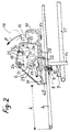
- Figures 2 to 5 are sectional views of the control box of the locking device provided in each of these carriages, these views illustrating the different successive phases of operation of the mechanism of this housing during removal of a carriage.
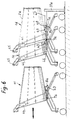
- Figure 6 is a view similar to Figure 1 but which shows another embodiment of the carts according to the invention.
- Figures 7 and 8 are vertical section views of another embodiment of a lockout box according to the invention.
- Figures 9 and 10 are views in horizontal section of a detail of this housing.
- FIG. 1 represents transport trolleys 1 of the type made available to customers in self-service stores.
- Each of these carriages therefore comprises a transport basket 2 fixed at a certain height above a base 3.
- the rear wall of the basket 2 is constituted by a movable flap 4 whose upper edge is hinged around a horizontal axis 5. This allows a series of such carriages to be embedded one inside the other as shown in FIG. 1. After such an embedding, the pivoting rear flap 5 of each carriage is kept raised by the upper part of the transport basket 2 of the trolley located behind it.
- each of these carriages is equipped with a deposit device according to the invention.
- each of these devices comprises a main box 6 which serves both as a control box containing the coin mechanism and as a box for mounting the lock of the corresponding device.
- This housing 6 is fixed on the pivoting flap 4 of each carriage at a distance L from its end.
- each carriage is equipped with a presence indicator 7 which is intended to act on the locking device provided on the carriage fitted around the carriage in question.
- this indicator consists of a permanent magnet 7 fixed to the front end of the upper frame 17 of the basket 2 of each carriage.
- means are provided on each carriage capable of detecting this indicator or of reacting to the presence of the latter.
- these means 8 are carried by the main unit 6 of each locking device.
- it is a movable finger of magnetic metal which is likely to be attracted by the permanent magnet constituted by the presence indicator 7 of the preceding carriage.
- This movable finger is subjected to the pressure of a spring 10 which tends to keep it raised in a position ensuring the blocking of a movable drawer 29 provided in the corresponding housing 6, which will moreover be described in more detail below.
- the lock also provided on the housing 6 of each locking device, comprises a bolt 14 secured to a rotary axis 15 carrying an operating lever 16.
- the bolt 14 In the locking position shown in FIG. 2, the bolt 14 extends roughly vertically downwards and its length is such that its end is then engaged inside the upper horizontal frame 17 of the basket 2 of the previous carriage 1, in this case the carriage designated by the reference la on the FIG. 1. Under these conditions, it is not possible to remove the carriage which is equipped with the locking box 6 described above, that is to say the carriage 1b in the example of FIG. 1.
- This mechanism comprises a main pawl 19 mounted pivoting about an axis 20 and which is provided with two teeth 21 and 22 cooperating with notches provided on a cam 23 integral with the rotary axis 15.
- This pawl is subjected to elastic pressure of a spring 24 and by means of a tab 25 it bears on a secondary pawl 26 mounted pivoting about an axis 27 and subjected to the elastic pressure of a spring 28.
- the housing 6 contains the sliding drawer 29 already mentioned, one end of which includes a receptacle 30 intended to receive a coin 18 for deposit.
- This drawer is subjected to the pressure of a spring 31 which tends to push it back into a position such that the receptacle 30 is located outside the housing 6 when the bolt 14 is in the locked position.
- the movable blocking finger 9 forming part of the detection means 8 is then held in the erased position, by the magnetic attraction resulting from the permanent element 7 serving as a witness to the presence of the preceding carriage. Consequently, it is possible to push the drawer 29 inside the housing 6. However, to obtain the unlocking of the rotary axis 15, it is necessary that a coin 18 serving as a deposit element has been at previously placed in the receptacle 30 of this drawer.
- this part acts on a shank 32 of the secondary pawl 26, which has the effect of releasing the main pawl 19 (see FIG. 3). It is therefore the tail 32 of the pawl 26 which detects the shape of the 18 coin or other valid payment item placed in the drawer receptacle.
- the front wall 33 of the receptacle 30 has an opening 34 intended to receive a shank 35 provided on the main pawl 19, which thus allows the coin 18 to act directly on this pawl.
- control box of this deposit device can be equipped with a mechanism automatically ensuring both the deletion of the bolt 14 when a deposit coin has been placed in this box, and the return of this bolt in its locked position when the carriage has been returned in place and fitted onto other carriages already located at this location.
- Each point of removal and return of carriages 1 is equipped with a particular structure allowing the fixing in place of a first carriage under the same conditions as if it were fitted on another carriage.
- This structure comprises two fixed posts 37 carrying projecting arches 38 intended to play the same role as the front end of a trolley basket, in order to be able to cause the rear flap 4 of the first trolley 1 to be raised. a girl.
- these two arches are joined by a horizontal stirrup 39 at the place where the bolt 14 for locking the first carriage in question can engage.
- this stirrup carries a presence indicator 7 identical to those provided on the carriages 1. Under these conditions, the carriage fitted on the poles 38 can be released under the same conditions as if it were fitted on other carriages. It can also be returned to this location under similar conditions.
- the box 6 groups together the first two parts mentioned above, as well as the last part, only the presence indicator being distinct.
- these four parts can be completely separate from each other by being connected by electrical circuits or other suitable connecting elements.
- the detection or reaction means could be constituted by an electric switch capable of being actuated by a permanent magnet 7, this switch being disposed at a point more or less distant from the control unit 6, while being connected, by an electrical circuit, to an electromagnetic coil controlling the movement of the movable blocking finger 9 or of any other member capable of playing the same role.
- the lock could be separated from the control unit 6 so that the movable bolt is placed in another place.
- the box of this lock would then be connected to the coin mechanism provided in the control box in order to receive the desired instructions from it, and vice versa.
- the locations of the various parts of the deposit device can be modified.
- the locking pin is mounted on the pivoting flap 4 of each carriage so as to be able to engage inside the upper frame 17 of the basket 2 of the preceding carriage.
- Figure 6 shows a variant in which there is provided a locking box 43 which is separate from the control box 44 of the corresponding locking device.
- the latter contains a coin mechanism intended to receive the planned deposit element.
- this box 44 is located at the top of each carriage and close to the operating handle 45 thereof.
- the locking box 43 it is arranged below the basket 2a of each carriage.
- the locking housing 43 is able to hang on, or to trap an element of the structure of the preceding carriage 1d in which the carriage considered is fitted.
- this structural element can be the rear lower cross member 46 of the basket 2a of the preceding carriage.
- the housing 43 contains a movable locking hook.
- this box also includes means 8a for detection or reaction which are capable of reacting to the presence of an appropriate indicator 7a provided on the carriage on which the carriage in question is fitted.
- This indicator may consist of a permanent magnet capable of acting on the detection means 8a which then play the role of a proximity detector of another carriage.
- the various corresponding mechanisms can be actuated by electromagnetic systems powered by batteries.
- the mobile elements to be driven have a very low mass, so that the energy consumption is relatively limited and allows a satisfactory longevity of the batteries used.
- This structure comprises a post 37a, carrying two horizontal arms 47 joined by a metal wire arch 48 capable of playing the role of the rear lower cross member 46 of the basket of a carriage.
- a metal wire arch 48 capable of playing the role of the rear lower cross member 46 of the basket of a carriage.
- this hoop is provided with a presence indicator 7a capable of acting on the detection or reaction means 8a provided on the first carriage 1d in the queue.
- FIG. 6 constitutes only an indicative example of the possible embodiments of the carriages according to the invention and of their recording device. Indeed, this carriage and this device can be the subject of many other different embodiments meeting the same design principles by providing for nesting of the carriages in each other, either from the rear (case of Figure 1) , or from the front (case of Figure 6).
- FIGS. 7 to 10 show another possible embodiment of a control and locking box 6a which is capable of being provided on a carriage.
- this casing contains a pivoting jaw 49 which is capable of grasping and trapping the upper front edge 50 of the basket of a neighboring carriage in interlocking mode, if this casing is fixed to the flap 4 from another cart.
- a number of members provided in this box are similar to those existing in the box 6 shown in Figures 2 to 5. These parts are designated by the same reference numeral, assigned the index "a”.
- a drawer 29a intended to receive a piece 18 of consignment.
- the presence of this part is controlled by a secondary pawl 26a which then releases a pawl main 19a. This in turn unlocks the pivoting jaw 49 which pivots in the direction F3 under the effect of the thrust exerted by the front edge 51 of the drawer 29a, so that the jaw 49 emerges from the front edge 50 of the basket of the neighboring carriage (see Figure 8). Under these conditions, the carriage, fitted with the box 6a in question, can be removed from the queue of waiting carriages for free use.
- this lever carries a metal counterweight 55 capable of being attracted by a permanent magnet provided on a neighboring carriage, and this when these two carriages are nested one inside the other.
- the pivoting jaw 49 As for the pivoting jaw 49, it has a shape such that its engagement, against the front edge 50 of the basket of another carriage, causes it to pivot in the direction of the arrow F4, and consequently its attachment to this front edge 50. Following this pivoting of the jaw 49, the retaining spoiler 52 releases the drawer 29a.
- the deposit element to be introduced into the control unit can consist, not only of a coin or a payment token, but in any other electronic means, for example a magnetic card of payment, or other similar item. It is then sufficient for the control box of the locking devices to be arranged accordingly.
Landscapes
- Physics & Mathematics (AREA)
- General Physics & Mathematics (AREA)
- Handcart (AREA)
- Prostheses (AREA)
- Coin-Freed Apparatuses For Hiring Articles (AREA)
Claims (11)
- Pfandvorrichtung zur Ausrüstung eines einschiebbaren Einkaufswagens (1), der Benutzem zur Verfügung gestellt ist, so daß diese über einen solchen Einkaufswagen (1) erst verfügen konnen, nachdem ein gewisser Geldbetrag als Pfand in die Vorrichtung eingegeben wurde, wobei eine Rückgabe von diesem möglich ist, wenn der Einkaufswagen (1) entsprechend einem festgelegten Punkt zurückgestellt ist und in die Einkaufswagen eingeschoben ist, die sich gegebenenfalls an diesen Punkt befinden, wobei die Vorrichtung aufweist ein Bediengehäuse (6), das an jedem Einkaufswagen (1) fest angebracht ist und mit einem Mechanismus versehen ist, der dadurch bedient wird, daß ein Zahlelement (18) in Sollstellung gebracht wird, und mit Mitteln zur Rückhaltung eines Einkaufswagens an den anderen verbunden ist,
dadurch gekennzeichnet,
daß die Vorrichtung aufweist:a) ein bewegliches Element (14 oder 49) zum Einhaken oder Verriegeln in oder gegen den Aufbau eines anderen Einkaufswagens (1), dessen Gehäuse an den entsprechenden Einkaufswagen (1) an einem solchen Punkt befestigt ist, daß das Element in Verriegelungsstellung in oder gegen den Aufbau eines anderen Einkaufswagens (1) eingreift, wenn diese beiden Einkaufswagen ineinander eingeschoben sind,b) ein Bediengehäuse (6), dessen Mechanismus dadurch auslösbar ist, daß ein Pfandelement in Sollstellung gebracht ist, um das Lösen des Einhak- oder Verriegelungselements auszulösen oder wenigstens zu gestatten,c) ein Erfassungs- oder Kontrollsystem mit zwei Abschnitten (7,7a; 8,8a), von denen einer (7,7a) mit dem Aufbau des Einkaufswagens (1) fest verbunden oder ein Teil von diesem ist, und von denen der andere (8,8a), der an dem Einkaufswagen (1) vorgesehen ist, so mit dem Mechanismus des Bediengehäuses (6) verbunden ist, daß bei dem Einschieben des betreffenden Einkaufswagens (1) auf oder in einen anderen Einkaufswagen ein fest verbundener Abschnitt (7,7a) eines Einkaufswagens einen anderen Abschnitt (8,8a) des anderen Einkaufswagens auslöst oder anzieht, um auf den Mechanismus des Bediengehäuses (6) des anderen Einkaufswagens einzuwirken, wohingegen unter der Einwirkung dieses Vorgangs dieser Mechanismus eine Rückgabe des Zahlelements, das zuvor aufgenommen wurde, gewährleistet ist und gleichzeitig das Zurückgehen des Einhak- oder Verriegelungselements (14,49) in seine Verriegelungsstellung gestattet ist. - Pfandvorrichtung nach Anspruch 1,
dadurch gekennzeichnet,
daß das System zur Kontrolle des Einschubs der Einkaufswagen in jedem von diesem aufweist:- einerseits ein Element (7), das zur aktiven oder passiven Anzeige des Vorhandenseins des entsprechenden Einkaufswagens dient, wenn ein anderer Einkaufswagen auf oder in diesen eingeschoben ist,- andererseits Mittel (8), die zum Erfassen einer solchen Anzeige oder zur Reaktion auf das Vorhandenseins eines solchen geeignet sind und die dazu geeignet sind, auf dem Mechanismus des Bediengehäuses (6) der Vorrichtung einzuwirken, die an dem Einkaufswagen vorgesehen ist, der diese Erfassungs- oder Reaktionsmittel aufweist. - Pfandvorrichtung nach Anspruch 2,
dadurch gekennzeichnet,
daß das Element zur Anzeige des Vorhandenseins eines Einkaufswagens durch einen an einem bestimmten Punkt jedes Einkaufswagens befestigten Dauermagneten (7) gebildet ist, wohingegen die Mittel, die zur Reaktion auf die Anwesenheit eines solchen geeignet sind, aus einem magnetischen, metallischen beweglichen Blockierelement (9) gebildet sind, das in Normalstellung das Zurückhalten eines Aufnahmeschiebers (29) für das Pfandelement gewährleistet und geeignet ist, dessen Freigabe zu gewährleisten, wenn dieses Element durch die magnetische Anziehung verschoben ist, die aus der Nähe der Anzeige (7) bei dem Ineinanderschieben der beiden resultiert, die auf einem anderen Einkaufswagen vorgesehen ist. - Pfandvorrichtung nach Anspruch 3,
dadurch gekennzeichnet,
daß das Einhak- oder Verriegelungselement auf dem Aufbau eines anderen Einkaufswagens aus einem Riegel (14) besteht, der durch eine Achse (15) getragen ist, die drehbar in dem Bediengehäuse (6) angebracht ist, und die mit einem Bedienhebel (16) versehen ist, wobei die Möglichkeiten zur Drehung dieser Achse durch eine oder zwei Klinken (19,26) gesteuert sind, die gegenüber dem Schieber (29) zur Aufnahme des Pfandelements so angebracht sind, daß sie durch diesen oder durch das von diesem getragene Pfandelement betätigt werden, wenn dieser in das Innere des Bediengehäuses (6) eingedrückt ist. - Pfandvorrichtung nach Anspruch 3,
dadurch gekennzeichnet,
daß das Einhak- oder Verriegelungselement auf dem Aufbau eines anderen Einkaufswagens aus einem Drehbacken (49) besteht, der zur Aufnahme und zum Einschließen eines Querelements dieses Aufbaus geeignet ist, beispielsweise dem oberen Rand vor dem Korb eines anderen Einkaufswagens, wobei die Möglichkeiten zur Drehung dieses Backens durch eine oder zwei Klinken (19a,26a) gesteuert sind, die so gegenuber dem Schieber (29a) zur Aufnahme eines Pfandelements angebracht sind, daß sie durch diesen oder das durch diesen getragene Pfandelement betätigt werden, wenn er in das Innere des Bediengehäuses (6a) eingedrückt wird. - Pfandvorrichtung nach Anspruch 1,
dadurch gekennzeichnet,
daß das Verriegelungsgehause (40) völlig separat von dem Bediengehäuse (6a) mit dem Zahlmechanismus ist, wobei letzterer zu erst mit einer elektrichen Schaltung zur Gewährleistung der Versorgung einer elektromagnetischen Spule geeignet ist, die zum Einwirken auf den Riegel der Verriegelung dient, so daß der entsprechende Einkaufswagen freigegeben wird, wenn das Pfandelement in dem Bediengehäuse (6a) vorhanden ist. - Pfandvorrichtung nach Anspruch 6,
dadurch gekennzeichnet,
daß die Mittel zur Reaktion auf die Anzeige des Vorhandenseins eines anderen Einkaufswagens durch das Verriegelungsgehäuse (40) gehalten sind und diese Mittel das Rückgabeelement für das Pfandelement in diesem Gehäuse steuern, um somit dessen Herausgabe zu gewährleisten, wenn der entsprechende Einkaufswagen auf oder in einen anderen Einkaufswagen geschoben ist. - Einschiebbarer Einkaufswagen,
dadurch gekennzeichnet,
daß er mit einer Pfandvorrichtung nach einem der Ansprüche 1 bis 7 versehen ist. - Einkaufswagen nach einem der Ansprüche 4 und 8,
dadurch gekennzeichnet,
daß das Verriegelungsgehäuse, das durch das Bediengehäuse (6) der Pfandvorrichtung gebildet sein kann, auf der hinteren herunterklappbaren Klappe (4) dieses Einkaufswagens in einem Abstand von seinem Ende so befestigt ist, daß der Riegel (14) dieser Verriegelung in das Innere des oberen Rahmens (17) des Korbes (2) eines anderen Einkaufswagens eingreifen kann, auf den der betreffende Einkaufswagen aufgeschoben ist. - Einkaufswagen nach Anspruch 9,
dadurch gekennzeichnet,
daß das Element, das zur Anzeige der Anwesenheit dient und aus einem Permanentmagneten besteht, auf der Vorderseite des oberen Abschnitts des Korbes (2) dieses Einkaufswagens befestigt ist, damit es unterhalb des Bediengehäuses (6) der Pfandvorrichtung eines anderen Einkaufswagens liegt, wenn sie ineinander eingeschoben sind, wobei die Mittel zur Erfassung oder zur Reaktion auf diese Vorhandenseinanzeige in dem Bediengehäuse (6) dieser Pfandvorrichtung vorgesehen sind. - Einkaufwagen nach Anspruch 8,
dadurch gekennzeichnet,
daß das Verriegelungsgehäuse (40) getrennt von dem Bediengehäuse (6a) vorgesehen ist, das den Zahlmechanismus aufweist, wobei es auf der Rückseite und an dem oberen Abschnitt des Einkaufswagens liegt, wobei das Bediengehäuse zuerst mit einer elektrischen Schaltung verbunden ist, die die Versorgung einer elektromagnetischen Spule gewährleisten kann, die zum Einwirken auf den Verriegelungsriegel bestimmt ist, um somit den entsprechenden Einkaufswagen freizugeben, wenn ein Pfandelement in dem Bediengehäuse (6a) vorhanden ist.
Applications Claiming Priority (2)
| Application Number | Priority Date | Filing Date | Title |
|---|---|---|---|
| FR8911323A FR2651349B1 (fr) | 1989-08-29 | 1989-08-29 | Dispositif de consignation pour chariot de type encastrable, et chariots pourvus d'un tel dispositif. |
| FR8911323 | 1989-08-29 |
Publications (2)
| Publication Number | Publication Date |
|---|---|
| EP0415805A1 EP0415805A1 (de) | 1991-03-06 |
| EP0415805B1 true EP0415805B1 (de) | 1994-12-28 |
Family
ID=9384956
Family Applications (1)
| Application Number | Title | Priority Date | Filing Date |
|---|---|---|---|
| EP19900402052 Expired - Lifetime EP0415805B1 (de) | 1989-08-29 | 1990-07-17 | Pfandvorrichtung für schiebbare Einkaufwagen und damit versehene Einkaufswagen |
Country Status (4)
| Country | Link |
|---|---|
| EP (1) | EP0415805B1 (de) |
| DE (1) | DE69015516T2 (de) |
| ES (1) | ES2068355T3 (de) |
| FR (1) | FR2651349B1 (de) |
Cited By (2)
| Publication number | Priority date | Publication date | Assignee | Title |
|---|---|---|---|---|
| US5425438A (en) * | 1993-02-12 | 1995-06-20 | Systec Ausbausysteme Gmbh | Deposit lock and token for a transport cart |
| EP0572879B1 (de) * | 1992-06-05 | 1997-03-19 | Vendoret Holding S.A. | Kopplungsschloss für Einkaufswagen |
Families Citing this family (3)
| Publication number | Priority date | Publication date | Assignee | Title |
|---|---|---|---|---|
| DE4111178A1 (de) * | 1991-04-06 | 1992-10-08 | Systec Ausbausysteme Gmbh | Transportwagen mit muenzschloss |
| DE4300852A1 (de) * | 1993-01-15 | 1994-07-21 | Wanzl Metallwarenfabrik Kg | Einrichtung zum Ausleihen von Transportwagen |
| DE19924869A1 (de) * | 1999-05-29 | 2000-11-30 | Wanzl Metallwarenfabrik Kg | Transportwagen |
Family Cites Families (3)
| Publication number | Priority date | Publication date | Assignee | Title |
|---|---|---|---|---|
| DE2554916C2 (de) * | 1975-12-06 | 1990-10-25 | Willi 7016 Gerlingen Kragl | Transportwagen |
| DE8121677U1 (de) * | 1981-07-23 | 1981-12-03 | Sonnendorfer, Horst, 8034 Germering | Einrichtung zum sicherstellen einer ordnungsgemaessen rueckgabe von ausgeliehenen einkaufswagen |
| GB2108745B (en) * | 1981-10-21 | 1985-04-11 | Bydale Eng Ltd | Trolley control system |
-
1989
- 1989-08-29 FR FR8911323A patent/FR2651349B1/fr not_active Expired - Fee Related
-
1990
- 1990-07-17 DE DE1990615516 patent/DE69015516T2/de not_active Expired - Fee Related
- 1990-07-17 EP EP19900402052 patent/EP0415805B1/de not_active Expired - Lifetime
- 1990-07-17 ES ES90402052T patent/ES2068355T3/es not_active Expired - Lifetime
Cited By (2)
| Publication number | Priority date | Publication date | Assignee | Title |
|---|---|---|---|---|
| EP0572879B1 (de) * | 1992-06-05 | 1997-03-19 | Vendoret Holding S.A. | Kopplungsschloss für Einkaufswagen |
| US5425438A (en) * | 1993-02-12 | 1995-06-20 | Systec Ausbausysteme Gmbh | Deposit lock and token for a transport cart |
Also Published As
| Publication number | Publication date |
|---|---|
| FR2651349B1 (fr) | 1991-10-18 |
| FR2651349A1 (fr) | 1991-03-01 |
| DE69015516T2 (de) | 1995-08-10 |
| DE69015516D1 (de) | 1995-02-09 |
| ES2068355T3 (es) | 1995-04-16 |
| EP0415805A1 (de) | 1991-03-06 |
Similar Documents
| Publication | Publication Date | Title |
|---|---|---|
| EP1081063B1 (de) | Vorrichtung zum automatisch durch Schwerkraft Verriegeln und Entriegeln des Deckels eines Behälters sowie Behälter mit einer derartigen Vorrichtung | |
| EP0205522B1 (de) | Vorrichtung zur abnehmbaren verbindung von einkaufswagen oder ähnlichem | |
| EP0509932A1 (de) | Verriegelungsvorrichtung für einen Behälter mit Deckel und Behälter mit einer solchen Vorrichtung | |
| EP0286770B1 (de) | Vorrichtung zur automatischen Zentrierung von Platten von verschiedenen Durchmessern auf die Lademittel eines Plattenspielers | |
| EP1639558A1 (de) | Automatisches zyklusspeichersystem | |
| WO1996029684A1 (fr) | Dispositif de consigne automatique pour bagages | |
| FR2553211A1 (fr) | Dispositif de consignation a monnaie | |
| EP0415805A1 (de) | Pfandvorrichtung für schiebbare Einkaufwagen und damit versehene Einkaufswagen | |
| EP1404605B1 (de) | Verriegelungsvorrichtung für schachttür mit unabhängiger notentriegelungsvorrichtung | |
| FR2645306A1 (fr) | Dispositif consigneur et deconsigneur pour objets utilitaires, tels que des chariots a bagages | |
| FR2686584A1 (fr) | Dispositif de blocage pour conteneur mobile de collecte d'ordures menageres. | |
| CA1285784C (fr) | Installation de consignation de chariots | |
| EP0161960B1 (de) | Einrichtung für die Aufbewahrung von Einkaufswagen | |
| FR3010988A1 (fr) | Conteneur de collecte des dechets dote d’un systeme perfectionne de commande d'ouverture/fermeture automatique de trappe de vidage | |
| FR2582605A1 (fr) | Installation de consignation d'objets, en particulier pour chariots, et dispositif de consignation correspondant | |
| EP0577472B1 (de) | Pfandvorrichtung und damit versehene an seinesgleichen schachtelbare Einkaufswagen | |
| FR2604010A2 (fr) | Monnayeur, notamment pour chariots de supermarches | |
| FR2612976A1 (fr) | Serrure a mecanisme de verrouillage-deverrouillage a l'aide d'un electro-aimant | |
| FR2612063A1 (fr) | Dispositif de rangement de chariots | |
| FR2601062A1 (fr) | Loquet de verrouillage a pene pivotant, destine notamment a une partie comportant une fermeture antipanique. | |
| EP0484851A1 (de) | Vorrichtung zum Einsammeln des Inhalts eines Münzaufnahmegeräts ohne betrügerisches Risiko | |
| EP0094284B1 (de) | Verriegelungsvorrichtung, insbesondere für Ersatzradhalterung | |
| FR2761500A1 (fr) | Machine semi-automatique pour apposer un dispositif anti-vol sur un article, notamment en tissu | |
| FR2828156A1 (fr) | Agencement d'une valise dans un coffre de vehicule automobile | |
| FR2651350A1 (fr) | Dispositif consigneur. |
Legal Events
| Date | Code | Title | Description |
|---|---|---|---|
| PUAI | Public reference made under article 153(3) epc to a published international application that has entered the european phase |
Free format text: ORIGINAL CODE: 0009012 |
|
| AK | Designated contracting states |
Kind code of ref document: A1 Designated state(s): DE ES GB IT SE |
|
| 17P | Request for examination filed |
Effective date: 19910412 |
|
| 17Q | First examination report despatched |
Effective date: 19930908 |
|
| GRAA | (expected) grant |
Free format text: ORIGINAL CODE: 0009210 |
|
| AK | Designated contracting states |
Kind code of ref document: B1 Designated state(s): DE ES GB IT SE |
|
| REF | Corresponds to: |
Ref document number: 69015516 Country of ref document: DE Date of ref document: 19950209 |
|
| ITF | It: translation for a ep patent filed | ||
| GBT | Gb: translation of ep patent filed (gb section 77(6)(a)/1977) |
Effective date: 19950307 |
|
| REG | Reference to a national code |
Ref country code: ES Ref legal event code: FG2A Ref document number: 2068355 Country of ref document: ES Kind code of ref document: T3 |
|
| PLBE | No opposition filed within time limit |
Free format text: ORIGINAL CODE: 0009261 |
|
| STAA | Information on the status of an ep patent application or granted ep patent |
Free format text: STATUS: NO OPPOSITION FILED WITHIN TIME LIMIT |
|
| 26N | No opposition filed | ||
| PGFP | Annual fee paid to national office [announced via postgrant information from national office to epo] |
Ref country code: GB Payment date: 19990714 Year of fee payment: 10 |
|
| PGFP | Annual fee paid to national office [announced via postgrant information from national office to epo] |
Ref country code: SE Payment date: 19990719 Year of fee payment: 10 |
|
| PGFP | Annual fee paid to national office [announced via postgrant information from national office to epo] |
Ref country code: ES Payment date: 19990730 Year of fee payment: 10 |
|
| PGFP | Annual fee paid to national office [announced via postgrant information from national office to epo] |
Ref country code: DE Payment date: 19990929 Year of fee payment: 10 |
|
| PG25 | Lapsed in a contracting state [announced via postgrant information from national office to epo] |
Ref country code: GB Free format text: LAPSE BECAUSE OF NON-PAYMENT OF DUE FEES Effective date: 20000717 |
|
| PG25 | Lapsed in a contracting state [announced via postgrant information from national office to epo] |
Ref country code: SE Free format text: LAPSE BECAUSE OF NON-PAYMENT OF DUE FEES Effective date: 20000718 Ref country code: ES Free format text: LAPSE BECAUSE OF NON-PAYMENT OF DUE FEES Effective date: 20000718 |
|
| GBPC | Gb: european patent ceased through non-payment of renewal fee |
Effective date: 20000717 |
|
| EUG | Se: european patent has lapsed |
Ref document number: 90402052.6 |
|
| PG25 | Lapsed in a contracting state [announced via postgrant information from national office to epo] |
Ref country code: DE Free format text: LAPSE BECAUSE OF NON-PAYMENT OF DUE FEES Effective date: 20010501 |
|
| REG | Reference to a national code |
Ref country code: ES Ref legal event code: FD2A Effective date: 20010810 |
|
| PG25 | Lapsed in a contracting state [announced via postgrant information from national office to epo] |
Ref country code: IT Free format text: LAPSE BECAUSE OF NON-PAYMENT OF DUE FEES;WARNING: LAPSES OF ITALIAN PATENTS WITH EFFECTIVE DATE BEFORE 2007 MAY HAVE OCCURRED AT ANY TIME BEFORE 2007. THE CORRECT EFFECTIVE DATE MAY BE DIFFERENT FROM THE ONE RECORDED. Effective date: 20050717 |