EP0484851A1 - Vorrichtung zum Einsammeln des Inhalts eines Münzaufnahmegeräts ohne betrügerisches Risiko - Google Patents
Vorrichtung zum Einsammeln des Inhalts eines Münzaufnahmegeräts ohne betrügerisches Risiko Download PDFInfo
- Publication number
- EP0484851A1 EP0484851A1 EP91118763A EP91118763A EP0484851A1 EP 0484851 A1 EP0484851 A1 EP 0484851A1 EP 91118763 A EP91118763 A EP 91118763A EP 91118763 A EP91118763 A EP 91118763A EP 0484851 A1 EP0484851 A1 EP 0484851A1
- Authority
- EP
- European Patent Office
- Prior art keywords
- hatch
- key
- sliding
- receptacle
- locking
- Prior art date
- Legal status (The legal status is an assumption and is not a legal conclusion. Google has not performed a legal analysis and makes no representation as to the accuracy of the status listed.)
- Granted
Links
- 238000003780 insertion Methods 0.000 claims abstract description 3
- 230000037431 insertion Effects 0.000 claims abstract description 3
- 230000000295 complement effect Effects 0.000 claims description 3
- 240000008042 Zea mays Species 0.000 description 4
- 238000000605 extraction Methods 0.000 description 3
- 230000000903 blocking effect Effects 0.000 description 2
- 230000033001 locomotion Effects 0.000 description 2
- 241000135309 Processus Species 0.000 description 1
- FQCKMBLVYCEXJB-MNSAWQCASA-L atorvastatin calcium Chemical compound [Ca+2].C=1C=CC=CC=1C1=C(C=2C=CC(F)=CC=2)N(CC[C@@H](O)C[C@@H](O)CC([O-])=O)C(C(C)C)=C1C(=O)NC1=CC=CC=C1.C=1C=CC=CC=1C1=C(C=2C=CC(F)=CC=2)N(CC[C@@H](O)C[C@@H](O)CC([O-])=O)C(C(C)C)=C1C(=O)NC1=CC=CC=C1 FQCKMBLVYCEXJB-MNSAWQCASA-L 0.000 description 1
- 229940082150 encore Drugs 0.000 description 1
- 238000005184 irreversible process Methods 0.000 description 1
- 230000000717 retained effect Effects 0.000 description 1
- 230000029305 taxis Effects 0.000 description 1
Images




Classifications
-
- G—PHYSICS
- G07—CHECKING-DEVICES
- G07F—COIN-FREED OR LIKE APPARATUS
- G07F9/00—Details other than those peculiar to special kinds or types of apparatus
- G07F9/06—Coin boxes
Definitions
- the present invention relates to a device for the collection, without risk of fraud, of the contents of a case of a coin-receiving apparatus for the payment of a service, property or any tax.
- the object of the present invention is to protect this operation from any risk of fraud on the part of those responsible for collecting such devices.
- the invention thus relates to a device for collecting the contents of a case of a coin receiving apparatus, comprising a receptacle comprising fixing means under said receiving apparatus which comprises complementary fixing means, said apparatus comprising a lower opening closed by a sliding bottom and said receptacle comprising an upper opening and being equipped with a sliding hatch, characterized in that said device comprises a locking means in the closed position of said sliding bottom, the locking and unlocking being controlled by a first security lock, said apparatus further comprising a member for controlling the sliding of said sliding bottom, in that said receptacle comprises a head comprising said fixing means and in which said sliding hatch is located, said head comprising a through channel at its upper end and at its end lower and in which is trapped a first security key whose lower end, provided with an operating lug opens at the lower end of said channel, said key being able to move along the axis of its rod so as to be able, when the receptacle is fixed under said collecting device, enter said first security lock, the rod of said key cooper
- said locking means in the closed position of said sliding bottom comprises a sliding bar perpendicular to the sliding of said bottom and comprising a locking lug, said bar comprising a rack meshing on a pinion belonging to said first security lock, the release being effected by the actuation of said security lock causing the translation of said bar so as to bring said lug in front of a notch made in said sliding bottom.
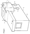
- a receptacle 1 intended for collecting the contents of a case of a coin receiving apparatus. This is for example a toll station for paid parking of motor vehicles.
- a receiving device 2 we see a small portion of such a receiving device 2 with its case 3 receiving coins.
- the receptacle 1 comprises a head 4 comprising two flanges 5 and 6 and slides 7 and 8 for its introduction under the receiving apparatus 2, in complementary slides 9 and 10.
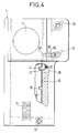
- the head 4 of the receptacle 1 is pierced with an upper opening 11 and is equipped with a sliding hatch 12, visible in FIG. 4, which is urged to close by a spring 13.
- the head 4 of the receptacle 1 forms at the same time a cover that folds down around a hinge 14 and closes on the box itself 15 with a security lock 16, called the second security lock, the key of which, called the second security key , is not in the possession of the terminal collector, but in the sole possession of the accountant responsible for the network of receiving devices.
- the head 4 of the receptacle 1 has a channel 17 (FIGS. 1 and 2) which opens at its upper end and at its lower end and into which is trapped a first security key 18 which comprises at its lower end an operating lug 19.
- the first key 18 is trapped in its channel thanks to a pin 20 introduced by a hole 21.
- the key 18 can move along the axis of its rod 22 between two limit positions, determined by the stop of the pin 20 against the ends upper 23 and lower 24 of a portion 30 of enlarged diameter of the channel 17.
- the key 18 is in the low position. In this position, as can be seen in the figure, the upper end of the key 18 is flush with the upper surface of the head 4.
- the key 18 carries a lug 25 which penetrates into a groove 26 formed in the channel 17.
- This arrangement which prevents the key from turning in the low position, aims to position it and therefore facilitate its introduction into a first security lock 27 ( Figure 3) carried by the receiving device 2. The role of this first security lock 27 will be defined later.
- the groove 26, in the lower end of the channel 17, after the enlargement 30, is angularly offset with respect to the groove portion 26 visible in FIG. 2 .
- the head 4 of the receptacle 1 also carries an operating key 28 of a control member 29 (FIG. 3) carried by the receiving device 2 and whose role will be explained below.
- the head 4 still carries a first finger 31, called the finger locking and a second finger 32.
- These two fingers 31 and 32 cooperate with the rod 22 of the security key 18.
- the rod 22 has a portion 33 of narrowed diameter.
- the fingers 31 and 32 are respectively provided with springs 34 and 35 for returning the fingers against the rod of the first safety key 18.
- the role of the locking finger 31 is to lock the sliding hatch 12, in the closed position, after collecting the money from the box 3 of the receiving device 2.
- the sliding hatch 12 carries a locking notch 36 ( Figure 4) which can penetrate the locking finger 31 ( Figure 10).
- the second finger 32 further cooperates with an arming lever 37 ( Figures 4 to 11).
- the cocking lever 37 cooperates with a pushing spring 38 which tends to push the curved end of the lever against the sliding hatch 12 while the other end of the lever carries an oblong light 39 crossed by a narrowed end 40 of the second finger 32.
- the purpose of the cocking lever 37 is to keep the sliding hatch 12 in the open position when, the receptacle 1 being empty, the network manager entrusts it to an attendant for the collection of a terminal (of a receiving apparatus).
- the sliding hatch 12 has a cocking notch 41 in which the end of the cocking lever 37 can be accommodated.
- the sliding hatch 12 is shown in the open position " army”. To arm the sliding hatch 12, the latter carries a handle 42 below (FIG. 2).
- This arming can only be carried out after opening of the head-cover 4 by means of the aforesaid second security key possessed only by the network manager.
- the role of the second finger 32 is twofold: it ensures the tilting of the cocking lever 37 and therefore its withdrawal from the cocking notch 41 when pushing up the first security key 18 for its introduction into the first security lock 27 of the receiving device 2. This action releases the hatch 12 which, pushed by the spring 13 (FIG. 4), begins to close, but is stopped in its movement by the end 40 of the second finger 32 which thus also serves stopper to the sliding hatch 12.
- Figures 7 and 8 show the mechanism in this position.
- the lower end of the receiving appliance 2 has a lower opening 43 closed by a sliding bottom 44.
- the sliding bottom 44 has an opening 45 which, in the open position of the sliding bottom, coincides with the lower opening 43.
- the receiving device 2 is provided with a sliding bar 46. Its sliding is perpendicular to the sliding of the sliding bottom 44 and it is guided by lights 47, 48 and guide pads 49 and 50.
- the bar 46 carries a lug of blocking 51, the function of which is to lock the sliding base 44 in the closed position.
- the sliding bottom 44 has a longitudinal notch 52 which can cooperate with the locking lug 51 when the bar 46 is in the unlocked position.
- the latter carries a rack 53 which cooperates with a pinion 54 belonging to the first security lock 27 actuated by the first security key 18 secured to the receptacle 1.
- the network manager gives an empty and locked receptacle 1 (Figure 1) to a collection attendant.
- the sliding hatch 12 is in the open position as seen in FIGS. 4, 5 and 6.
- the first safety key 18 is in the low position, its upper end flush with the upper face of the head 4 of the receptacle (as in seen in Figure 2) (In Figure 2 however, the hatch 12 is in the closed position).
- the attendant plugs his receptacle 1 under the receiving device 2 in the position shown in FIG. 2.
- the first finger 31 moves back while the second finger 32 advances, pushing the lever arming 37 against the force of the spring 38, the lever exiting from the arming notch 41.
- the hatch 12, pushed by the spring 13 (FIG. 4), is released and begins to close, but is immediately stopped by the end 40 of the second finger 32.
- the attendant then turns the security key 18 to advance the locking bar 46 (FIG. 3) so that the locking lug 51 is in front of the notch 52.
- the attendant then opens the sliding bottom 44 of the device 2 by actuating the operating key 28 ( Figure 1).
- the security key 18 in order to remove the receptacle 1 from below the receiving apparatus 2, the security key 18 must be lowered since it is located in the lock 27 which belongs to the apparatus 2, but that cannot be remove this key by turning it, that is to say again blocking the bottom 44, but for power, it is first necessary to close the bottom 44 with the operating key 28.
- the attendant closes the bottom 44 with the operating key 28, then blocks it in the closed position by turning the first security key 18. It is then, and only then that he can begin to lower the key 18 as shown in Figure 9, but in doing so, the second finger 32, pushed by the spring 35, back against the narrowed portion 33 of the key 18 so that the sliding door 12, which was retained in its closing movement by the part 40 of the second finger 32, is now free to close completely.
- the key 18 can only be placed in the low position, as can be seen in FIG. 10, and which is the only position of the key allowing the extraction of the receptacle 1 from below the receiving apparatus 2, only if the hatch 12 is completely closed so that the locking notch 36 is located exactly in front of the first finger 31. If this is not so, if for one reason or another, the hatch 12 is not not completely closed, the key cannot be lowered completely because the end of the first finger 31 abuts the hatch 12.
- FIG. 11 shows the finger 31 in the locking notch 36.
- FIGS. 10 and 11 therefore correspond to the terminal phase, and it is this which also corresponds to FIG. 2.
- the attendant can then extract the receptacle 1 from beneath the receiving apparatus 2.
Landscapes
- Physics & Mathematics (AREA)
- General Physics & Mathematics (AREA)
- Control Of Vending Devices And Auxiliary Devices For Vending Devices (AREA)
- Buckles (AREA)
Applications Claiming Priority (2)
| Application Number | Priority Date | Filing Date | Title |
|---|---|---|---|
| FR9013932 | 1990-11-09 | ||
| FR9013932A FR2669138B1 (fr) | 1990-11-09 | 1990-11-09 | Dispositif pour la collecte, sans risque de fraude, du contenu d'une caisse d'un appareil recepteur de pieces de monnaie. |
Publications (2)
| Publication Number | Publication Date |
|---|---|
| EP0484851A1 true EP0484851A1 (de) | 1992-05-13 |
| EP0484851B1 EP0484851B1 (de) | 1995-04-12 |
Family
ID=9402031
Family Applications (1)
| Application Number | Title | Priority Date | Filing Date |
|---|---|---|---|
| EP19910118763 Expired - Lifetime EP0484851B1 (de) | 1990-11-09 | 1991-11-04 | Vorrichtung zum Einsammeln des Inhalts eines Münzaufnahmegeräts ohne betrügerisches Risiko |
Country Status (2)
| Country | Link |
|---|---|
| EP (1) | EP0484851B1 (de) |
| FR (1) | FR2669138B1 (de) |
Cited By (5)
| Publication number | Priority date | Publication date | Assignee | Title |
|---|---|---|---|---|
| US5611483A (en) * | 1994-10-11 | 1997-03-18 | Glenview Security Systems | Coin and currency receptacle assembly for money operated machines |
| FR2819333A1 (fr) * | 2001-01-09 | 2002-07-12 | Philippe Benard | Obturateur coulissant pour bac a monnaie d'horodateur de parking |
| US6598787B1 (en) | 2002-01-17 | 2003-07-29 | Glenview Systems, Inc. | Coin receptacle assembly with door locking mechanism |
| KR20030082703A (ko) * | 2002-04-18 | 2003-10-23 | 미산메카트로닉스 주식회사 | 동전 출납기용 동전공급 콘테이너 장치 |
| EP1655701A1 (de) * | 2004-11-08 | 2006-05-10 | Ascom | Ver- bzw. Entriegelungsystem |
Citations (2)
| Publication number | Priority date | Publication date | Assignee | Title |
|---|---|---|---|---|
| US3677461A (en) * | 1970-07-23 | 1972-07-18 | Reynolds Products | Security device |
| US3961744A (en) * | 1975-04-23 | 1976-06-08 | Henry R. Stiffel | Coin collecting system for parking meters |
-
1990
- 1990-11-09 FR FR9013932A patent/FR2669138B1/fr not_active Expired - Fee Related
-
1991
- 1991-11-04 EP EP19910118763 patent/EP0484851B1/de not_active Expired - Lifetime
Patent Citations (2)
| Publication number | Priority date | Publication date | Assignee | Title |
|---|---|---|---|---|
| US3677461A (en) * | 1970-07-23 | 1972-07-18 | Reynolds Products | Security device |
| US3961744A (en) * | 1975-04-23 | 1976-06-08 | Henry R. Stiffel | Coin collecting system for parking meters |
Cited By (6)
| Publication number | Priority date | Publication date | Assignee | Title |
|---|---|---|---|---|
| US5611483A (en) * | 1994-10-11 | 1997-03-18 | Glenview Security Systems | Coin and currency receptacle assembly for money operated machines |
| FR2819333A1 (fr) * | 2001-01-09 | 2002-07-12 | Philippe Benard | Obturateur coulissant pour bac a monnaie d'horodateur de parking |
| US6598787B1 (en) | 2002-01-17 | 2003-07-29 | Glenview Systems, Inc. | Coin receptacle assembly with door locking mechanism |
| KR20030082703A (ko) * | 2002-04-18 | 2003-10-23 | 미산메카트로닉스 주식회사 | 동전 출납기용 동전공급 콘테이너 장치 |
| EP1655701A1 (de) * | 2004-11-08 | 2006-05-10 | Ascom | Ver- bzw. Entriegelungsystem |
| FR2877646A1 (fr) * | 2004-11-08 | 2006-05-12 | Ascom Sa | Systeme de verrouillage/deverrouillage |
Also Published As
| Publication number | Publication date |
|---|---|
| FR2669138A1 (fr) | 1992-05-15 |
| EP0484851B1 (de) | 1995-04-12 |
| FR2669138B1 (fr) | 1992-12-31 |
Similar Documents
| Publication | Publication Date | Title |
|---|---|---|
| EP0509932B1 (de) | Verriegelungsvorrichtung für einen Behälter mit Deckel und Behälter mit einer solchen Vorrichtung | |
| EP1001119B1 (de) | Kraftfahrzeugtürschloss mit innerer und/oder äusserer elektrischer Verriegelungs-/Entriegelungsvorrichtung | |
| EP0484851B1 (de) | Vorrichtung zum Einsammeln des Inhalts eines Münzaufnahmegeräts ohne betrügerisches Risiko | |
| FR2624287A1 (fr) | Receptacle amovible de stockage de pieces de monnaie pour machines actionnees par l'introduction de pieces de monnaie | |
| EP1805731B1 (de) | Mit wechselbarer münzaufnahme ausgestattete geldhandhabungseinheit | |
| WO2003006354A1 (fr) | Dispositif de verrouillage d'une porte paliere a deverrouillage de secours independant | |
| EP0305485B1 (de) | Schloss mit elektromagnetischer verriegelung/entriegelung | |
| EP0415805B1 (de) | Pfandvorrichtung für schiebbare Einkaufwagen und damit versehene Einkaufswagen | |
| EP0022694B1 (de) | Kassette für einen Stapel von Blättern in einer Maschine zum Abgeben derselben | |
| FR2814190A1 (fr) | Mecanisme de manoeuvre de porte | |
| FR2826682A1 (fr) | Serrure et porte correspondante | |
| FR2481735A1 (fr) | Dispositif de fermeture a ressort pour parties de vehicule verrouillables | |
| FR2482648A2 (fr) | Systeme de verrouillage, notamment pour capot de vehicule | |
| EP3588526B1 (de) | Sicherungshalterung | |
| EP0316227B1 (de) | Münzbetätigte Vorrichtung | |
| FR2674282A1 (fr) | Serrure de commande de deux barres coulissantes de fermeture pour condamnation en deux points haut et bas. | |
| FR2681090A1 (fr) | Serrure dans laquelle la decondamnation du pene est commandee par un electro-aimant. | |
| CH339763A (fr) | Appareil collecteur de pièces de monnaie | |
| FR2646458A1 (fr) | Dispositif de fermeture a verrouillage automatique par commande centralisee pour porte ou analogue | |
| FR2463248A1 (fr) | Dispositif de fermeture perfectionne a verrouillage automatique | |
| FR2740586A1 (fr) | Ensemble d'un coffret et d'une tirelire a acces controle | |
| EP0774373B1 (de) | Vorrichtung zum Betanken des Kraftstoffbehälters eines Kraftfahrzeuges | |
| BE562983A (de) | ||
| BE389043A (de) | ||
| FR2506820A1 (fr) | Dispositif de fermeture et de blocage, en particulier pour des sacs, des valises et similaires |
Legal Events
| Date | Code | Title | Description |
|---|---|---|---|
| PUAI | Public reference made under article 153(3) epc to a published international application that has entered the european phase |
Free format text: ORIGINAL CODE: 0009012 |
|
| AK | Designated contracting states |
Kind code of ref document: A1 Designated state(s): CH ES FR IT LI SE |
|
| 17P | Request for examination filed |
Effective date: 19921102 |
|
| 17Q | First examination report despatched |
Effective date: 19940422 |
|
| RAP1 | Party data changed (applicant data changed or rights of an application transferred) |
Owner name: HII S.A. |
|
| GRAA | (expected) grant |
Free format text: ORIGINAL CODE: 0009210 |
|
| AK | Designated contracting states |
Kind code of ref document: B1 Designated state(s): CH ES FR IT LI SE |
|
| PG25 | Lapsed in a contracting state [announced via postgrant information from national office to epo] |
Ref country code: IT Free format text: LAPSE BECAUSE OF FAILURE TO SUBMIT A TRANSLATION OF THE DESCRIPTION OR TO PAY THE FEE WITHIN THE PRE;WARNING: LAPSES OF ITALIAN PATENTS WITH EFFECTIVE DATE BEFORE 2007 MAY HAVE OCCURRED AT ANY TIME BEFORE 2007. THE CORRECT EFFECTIVE DATE MAY BE DIFFERENT FROM THE ONE RECORDED.SCRIBED TIME-LIMIT Effective date: 19950412 Ref country code: ES Free format text: THE PATENT HAS BEEN ANNULLED BY A DECISION OF A NATIONAL AUTHORITY Effective date: 19950412 |
|
| PG25 | Lapsed in a contracting state [announced via postgrant information from national office to epo] |
Ref country code: SE Effective date: 19950712 |
|
| PG25 | Lapsed in a contracting state [announced via postgrant information from national office to epo] |
Ref country code: LI Effective date: 19951130 Ref country code: CH Effective date: 19951130 |
|
| PLBE | No opposition filed within time limit |
Free format text: ORIGINAL CODE: 0009261 |
|
| STAA | Information on the status of an ep patent application or granted ep patent |
Free format text: STATUS: NO OPPOSITION FILED WITHIN TIME LIMIT |
|
| 26N | No opposition filed | ||
| REG | Reference to a national code |
Ref country code: CH Ref legal event code: PL |
|
| PG25 | Lapsed in a contracting state [announced via postgrant information from national office to epo] |
Ref country code: FR Effective date: 19960731 |
|
| REG | Reference to a national code |
Ref country code: FR Ref legal event code: ST |