EP0415841A1 - Verfahren und Vorrichtung zur Bildung von magnetisierten Zonen auf einem magnetisierbaren Körper - Google Patents
Verfahren und Vorrichtung zur Bildung von magnetisierten Zonen auf einem magnetisierbaren Körper Download PDFInfo
- Publication number
- EP0415841A1 EP0415841A1 EP90402375A EP90402375A EP0415841A1 EP 0415841 A1 EP0415841 A1 EP 0415841A1 EP 90402375 A EP90402375 A EP 90402375A EP 90402375 A EP90402375 A EP 90402375A EP 0415841 A1 EP0415841 A1 EP 0415841A1
- Authority
- EP
- European Patent Office
- Prior art keywords
- conductor
- magnetic field
- magnetizing
- magnetic
- pairs
- Prior art date
- Legal status (The legal status is an assumption and is not a legal conclusion. Google has not performed a legal analysis and makes no representation as to the accuracy of the status listed.)
- Withdrawn
Links
- 238000000034 method Methods 0.000 title claims description 9
- 230000005415 magnetization Effects 0.000 claims abstract description 35
- 239000004020 conductor Substances 0.000 claims description 68
- 238000013016 damping Methods 0.000 claims description 15
- 230000035515 penetration Effects 0.000 claims description 4
- 238000004804 winding Methods 0.000 description 17
- 230000004907 flux Effects 0.000 description 9
- 239000012212 insulator Substances 0.000 description 5
- 238000004519 manufacturing process Methods 0.000 description 4
- 239000000463 material Substances 0.000 description 4
- 229920006395 saturated elastomer Polymers 0.000 description 3
- 208000031968 Cadaver Diseases 0.000 description 2
- RYGMFSIKBFXOCR-UHFFFAOYSA-N Copper Chemical compound [Cu] RYGMFSIKBFXOCR-UHFFFAOYSA-N 0.000 description 2
- XAGFODPZIPBFFR-UHFFFAOYSA-N aluminium Chemical compound [Al] XAGFODPZIPBFFR-UHFFFAOYSA-N 0.000 description 2
- 229910052782 aluminium Inorganic materials 0.000 description 2
- 229910052802 copper Inorganic materials 0.000 description 2
- 239000010949 copper Substances 0.000 description 2
- 241000357293 Leptobrama muelleri Species 0.000 description 1
- BQCADISMDOOEFD-UHFFFAOYSA-N Silver Chemical compound [Ag] BQCADISMDOOEFD-UHFFFAOYSA-N 0.000 description 1
- QJVKUMXDEUEQLH-UHFFFAOYSA-N [B].[Fe].[Nd] Chemical compound [B].[Fe].[Nd] QJVKUMXDEUEQLH-UHFFFAOYSA-N 0.000 description 1
- 230000015572 biosynthetic process Effects 0.000 description 1
- KPLQYGBQNPPQGA-UHFFFAOYSA-N cobalt samarium Chemical compound [Co].[Sm] KPLQYGBQNPPQGA-UHFFFAOYSA-N 0.000 description 1
- 238000010586 diagram Methods 0.000 description 1
- 230000004048 modification Effects 0.000 description 1
- 238000012986 modification Methods 0.000 description 1
- 229910001172 neodymium magnet Inorganic materials 0.000 description 1
- AJCDFVKYMIUXCR-UHFFFAOYSA-N oxobarium;oxo(oxoferriooxy)iron Chemical compound [Ba]=O.O=[Fe]O[Fe]=O.O=[Fe]O[Fe]=O.O=[Fe]O[Fe]=O.O=[Fe]O[Fe]=O.O=[Fe]O[Fe]=O.O=[Fe]O[Fe]=O AJCDFVKYMIUXCR-UHFFFAOYSA-N 0.000 description 1
- 150000002910 rare earth metals Chemical group 0.000 description 1
- 229910000938 samarium–cobalt magnet Inorganic materials 0.000 description 1
- 229910052709 silver Inorganic materials 0.000 description 1
- 239000004332 silver Substances 0.000 description 1
- 229910052712 strontium Inorganic materials 0.000 description 1
- CIOAGBVUUVVLOB-UHFFFAOYSA-N strontium atom Chemical compound [Sr] CIOAGBVUUVVLOB-UHFFFAOYSA-N 0.000 description 1
- 229910000859 α-Fe Inorganic materials 0.000 description 1
Images

Classifications
-
- H—ELECTRICITY
- H01—ELECTRIC ELEMENTS
- H01F—MAGNETS; INDUCTANCES; TRANSFORMERS; SELECTION OF MATERIALS FOR THEIR MAGNETIC PROPERTIES
- H01F41/00—Apparatus or processes specially adapted for manufacturing or assembling magnets, inductances or transformers; Apparatus or processes specially adapted for manufacturing materials characterised by their magnetic properties
- H01F41/02—Apparatus or processes specially adapted for manufacturing or assembling magnets, inductances or transformers; Apparatus or processes specially adapted for manufacturing materials characterised by their magnetic properties for manufacturing cores, coils, or magnets
-
- H—ELECTRICITY
- H01—ELECTRIC ELEMENTS
- H01F—MAGNETS; INDUCTANCES; TRANSFORMERS; SELECTION OF MATERIALS FOR THEIR MAGNETIC PROPERTIES
- H01F13/00—Apparatus or processes for magnetising or demagnetising
Definitions
- the present invention relates to the manufacture of magnets. It relates more particularly to a new apparatus and method for forming a plurality of magnetic poles on a magnetizable body in a series of successive steps when it is difficult, inconvenient or impossible to magnetize the entire magnetizable body in a single step.
- a conventional way of making magnets is to use a single stationary device which magnetizes the annular magnetizable element to simultaneously form all of the pairs of poles.
- Examples of devices and processes for making magnets to form all of pole pairs in one step are disclosed in US Patent No. 4,614,929 dated September 30, 1986 in the name of Tsukada et al, and entitled “Process for magnet manufacturing "; and in U.S. Patent No. 4,773,753 dated April 12, 1988 in the name of Claude Oudet, and entitled "A multipolar magnetization".
- the new method and apparatus according to the invention for magnetizing a magnetizable element can be used in cases where one is limited from the space point of view and where a one-stage magnetization apparatus cannot be used.
- the consecutive steps form a series of magnetized zones on a magnetizable body.
- this method one must overcome certain difficulties, if one is based on the method of magnetizing a magnetizable body in a single step as disclosed in US Patents No. 4,614,929 and 4,737,753.
- the apparatus should be designed in such a way that the extent of each pair of poles is carefully controlled to correspond to a predetermined area.
- the apparatus must also be designed in such a way that after the formation of the first or more pairs of poles, the application of any subsequent magnetization does not erase or significantly modify the pairs of poles already magnetized.
- magnetization over the entire length of a flat body or the entire circumference of an annular body, for example, must result in pairs of equidistant poles with flux levels of substantially equal amplitudes.
- the present invention involves a magnetization conductor.
- a source of electric current pulses delivers an electric current pulse into the magnetizing conductor to create a magnetic field.
- At least one means of damping the magnetic field is provided.
- the damping means is positioned in such a way that in its vicinity, the magnetic field created by the pulse delivered to the magnetizing conductor is damped. So an electrical current pulse delivered to the magnetizing conductor creates a magnetic field which penetrates the part of the magnetizable body adjacent to the magnetizing conductor, to create the zones of magnetized polar pairs desired, with practically no penetration of the part of the magnetizable body adjacent to the damping means.
- the new method of manufacturing a magnet consists in first forming, in a first step, at least one pair of poles on the magnetizable body in a predetermined area; then, during consecutive steps, to form pairs of additional magnetic poles on the magnetizable element until the entirety of the magnetizable element is magnetized with the number of pairs of poles desired. All the successive pairs of poles are formed without appreciably modifying the magnetization of the pairs of poles previously formed, so that the area of each pair of poles is carefully controlled and that the resulting magnet has pairs of poles whose levels of flows are substantially of the same magnitude.
- the apparatus of the invention for forming a series of magnetized zones on a magnetizable body comprises a support 10.
- the support 10 comprises several vertical bosses 12, 14, 16 and 18 which are horizontally separated and define several grooves 20, 22 , 24 horizontally spaced.
- a magnetizing conductor 26 is housed in the groove 22.
- Secondary electrical conductors 28 and 30 are housed in the grooves 20 and 24, respectively.
- the secondary electrical conductors 28 and 30 are also spaced horizontally and vertically from the magnetization conductor 26. They are also spaced horizontally from the magnetization body in opposite directions, and vertically in the same direction.
- a pulse generator 3 is used to deliver electrical pulses to the magnetization conductor 26, and in the parallel connection of the secondary electrical conductors 28 and 30.
- the intensity of the current flowing in the magnetization conductor 26 is double that of the current flowing in each of the secondary electrical conductors 28 and 30.
- the magnetizable body 34 may have any shape, including a thin, flat shape or an annular shape. If it is annular, the bosses 12, 14, 16 and 18 will have curved surfaces, as necessary to conform to the curvature of the body 34.
- the support 10 is placed against the element 34 to be magnetized.
- the pulse generator is then started to excite the magnetization conductor 26 and the secondary electrical conductors 28 and 30. As shown in FIG. 1, in the magnetizing conductor 26, the electric current leaves the surface of the paper (represented by the sign in the shape of a circular point), and in the conductors 28 and 30, it penetrates into the paper (represented by the circled cross) .
- An S pole forms on the upper part of the zone 36 of the body 34.
- An N pole forms on the lower part of the zone 36.
- an N pole forms on the upper part of the zone 38 of the body 34
- a pole S forms on the lower part of the zone 38.
- the magnetic flux and the direction of the magnetic flux can be represented by the arrows shown in FIG. 1. Note that the arrows are directed clockwise.
- a pair of poles means an N pole and an S pole which are shown to be spaced apart vertically in FIG. 1 and the other figures. Therefore, a pair of poles has been formed in zone 36; a second pair of poles has been formed in zone 38.
- the magnetizable element 34 can be made of barium ferrite, strontium ferrite, or of materials of the rare earth group, such as neodymium-iron-boron, or samarium-cobalt, and it is preferably anisotropic.
- a steel back 31 tends to straighten the path of the flux so that it is vertical through the magnetizable element 34.
- a pole S is formed in the upper part of the zone 40 of the body 34; an N pole is formed in the lower part of the zone 40.
- the image of the flow can be represented by the arrows which, in FIG. 2, are directed clockwise around the magnetizing conductor 26.
- the remaining part of the body 34 is magnetized by successively moving either the support 10 or the body 34 by the appropriate distance, and alternately reversing the direction of the current in the magnetization conductor 26 and the secondary electrical conductors 28 and 30 until the entire part 34 is magnetized by presenting the plurality of pairs of magnetic poles.
- the boss 18, the adjacent groove 24 and the conductor 30 housed in the groove 24, as well as the boss 12, the adjacent groove 20 and the conductor 28 housed in the groove 20 are important parts of the support 10. They each form a means magnetic field damping. They are spaced by a predetermined distance from the magnetic conductor 26, and positioned in such a way that the magnetic field created by the pulse delivered to the magnetization conductor 26 is damped by the field damping means. magnetic, so that the electric current pulse delivered to the magnetizing conductor 26 creates a magnetic field which only penetrates the zones 38 and 40 of the magnetizable body, FIG. 2, with practically no penetration of the parts of the body 34 adjacent to the damping means.
- the clockwise magnetic flux would pass into the zone 36 of the body 34 and would significantly erase or reduce the magnetic flux already formed in the zone 36.
- the entire zone 38 of the magnetizable body 34 doesn’t is not magnetically saturated. Namely that the part of the zone 38 closest to the magnetization conductor 26 is saturated, but that the amplitudes of the magnetic flux fall below the magnetic saturation in the parts of zone 38 furthest from the conductor of magnetization 26. However, as can be seen by observing FIG. 2, this part of zone 38 which was not saturated during of the step shown in FIG. 1 can be during the step shown in FIG. 2.
- the boundaries of the zones 36 and 38 are clearly defined by the location of the magnetization conductor 26 at each magnetization step.
- the continuous vertical line 37 indicates the clearly defined border during the magnetization of the zones 36 and 38.
- the continuous vertical line 39 indicates the clearly defined border of the zone 36 formed in an anterior magnetization step placing the magnetization conductor 26 at the above the vertical line 39.
- the zones can be modified by appropriately positioning the magnetizing conductor 26 on the magnetizable body 34.
- the zone 36 could be reduced, or increased, by placing the magnetizing conductor 26 at the above the broken line 42, or above the broken line 44, respectively, in the step preceding the step shown in FIG. 1.
- magnetic field isolators used with variable magnetic fields can be placed near the bosses 18 and 12, respectively.
- magnetic field isolators 45 and 47 shown in broken lines, can be accommodated in the grooves 20 and 24, respectively.
- the insulators are made of a material with high conductivity such as aluminum, copper or silver.
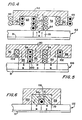
- the support 50 is provided with a plurality of vertical bosses 52, 54 and 56 defining the grooves 58 and 60.
- the magnetizing conductor is a winding 64 which is formed around the boss 54.
- the secondary electrical conductors are windings 66 and 68 which are formed around the bosses 52 and 56, respectively.
- a pair of poles is formed in the area 70 of the magnetizable body 62, as shown.
- the body of the support 50 is then moved along the magnetizable body 62, or else the magnetizable body 62 is moved relative to the body of the support 50 to the next area to be magnetized.
- the current in the magnetization winding 64 and the current in the secondary electrically conductive windings 66 and 68 are reversed to form a pair of poles in opposite directions with respect to the pair of poles of the zone 70.
- the magnetic field damping means comprises the secondary electric conductor winding 66 formed around the boss 52 and the secondary electric conductor winding 68 formed around the boss 56.
- windings are spaced from the magnetization winding 64 of a predetermined distance and are designed such that the magnetic field created by the pulses delivered to the magnetizing conductor is damped by the magnetic field damping means. Consequently, an electric current pulse supplied to the magnetizing conductor 64 creates a magnetic field which penetrates the area 70 of the magnetizable body 62 without practically any penetration of the parts of the magnetizable body adjacent to the damping means.
- the windings 64, 66 and 68 can be part of a single wire.
- the support 80 includes a plurality of bosses 82, 84, 86, 88 and 90 defining a plurality of separate grooves 92, 94, 96 and 98.
- the lower ends of the bosses 82 and 90 are spaced a predetermined distance from the magnetizable body 106.
- the magnetization conductor 100 is wound around the boss 86.
- Secondary electrical conductors 102 and 104 are housed in the grooves 92 and 98, respectively.
- the secondary electrical conductors 102 and 104 respectively housed in the grooves 92 and 98, ensure the damping of any magnetic field which would otherwise be present in the bosses 82 and 90, in order to prevent any magnetization of the adjacent parts of the body 106 to those which must be magnetized, to prevent the erasure or the modification of the pairs of poles previously formed on the body 106, and to magnetically saturate the zones which have not been completely so.
- the conductors 100, 102 and 104 can be part of a single wire.
- FIG. 6 An apparatus for forming a series of magnetic zones on a magnetizable body, it is also possible to use a material with high conductivity.
- a material with high conductivity such an arrangement is shown in FIG. 6.
- the support 110 is provided with a groove 112 centered horizontally, in which is housed the magnetizing conductor 114.
- an insulator of variable magnetic field 116 is provided as a magnetic insulator.
- the magnetic insulator 116 has bosses 118 and 120 spaced apart horizontally. These bosses are spaced a predetermined distance from the magnetizing conductor 114. They are both in contact with the magnetizable body 122.
- the high conductivity material used as a variable magnetic field insulator 116 can, for example , be based on aluminum or copper.
- the two zones of pole pairs shown are created. Then, either the magnetizable body 122, or the entire support 110 with its magnetic field isolator 116, is moved to the next location, and the magnetization current in the magnetization winding 114 is reversed to form the next pair of poles.
- the magnetic fields created by the current flow in the magnetization winding 114 are reflected by the magnetic field isolator 116.
- the magnetic field isolator 116 includes the bosses 118 and 120, these serve to dampen any field magnetic which could tend to penetrate the magnetizable element 122 near the zones of the pairs of poles formed.
Landscapes
- Engineering & Computer Science (AREA)
- Power Engineering (AREA)
- Manufacturing & Machinery (AREA)
- Manufacturing Cores, Coils, And Magnets (AREA)
- Magnetic Resonance Imaging Apparatus (AREA)
- Magnetic Treatment Devices (AREA)
- Hard Magnetic Materials (AREA)
Applications Claiming Priority (2)
| Application Number | Priority Date | Filing Date | Title |
|---|---|---|---|
| US07/400,635 US5025240A (en) | 1989-08-30 | 1989-08-30 | Method and apparatus for forming magnetized zones on a magnetizable body |
| US400635 | 1989-08-30 |
Publications (1)
| Publication Number | Publication Date |
|---|---|
| EP0415841A1 true EP0415841A1 (de) | 1991-03-06 |
Family
ID=23584405
Family Applications (1)
| Application Number | Title | Priority Date | Filing Date |
|---|---|---|---|
| EP90402375A Withdrawn EP0415841A1 (de) | 1989-08-30 | 1990-08-28 | Verfahren und Vorrichtung zur Bildung von magnetisierten Zonen auf einem magnetisierbaren Körper |
Country Status (8)
| Country | Link |
|---|---|
| US (1) | US5025240A (de) |
| EP (1) | EP0415841A1 (de) |
| JP (1) | JPH0636404B2 (de) |
| KR (1) | KR0171585B1 (de) |
| CN (1) | CN1044942C (de) |
| AU (1) | AU625366B2 (de) |
| BR (1) | BR9004279A (de) |
| FR (1) | FR2651367B1 (de) |
Families Citing this family (22)
| Publication number | Priority date | Publication date | Assignee | Title |
|---|---|---|---|---|
| JPH04120210U (ja) * | 1991-04-15 | 1992-10-27 | 鐘淵化学工業株式会社 | 等間隔着磁ヨーク |
| AU4683493A (en) * | 1992-07-17 | 1994-02-14 | Linaeum Corporation | Audio transducer with etched voice coil |
| JPH11513797A (ja) * | 1995-10-17 | 1999-11-24 | サイエンティフィック ジェネリクス リミテッド | 位置検出エンコーダー |
| US5777402A (en) * | 1996-06-24 | 1998-07-07 | Anorad Corporation | Two-axis motor with high density magnetic platen |
| US6819023B1 (en) * | 1997-07-11 | 2004-11-16 | Seagate Technology Llc | Magnetizing apparatus |
| US6467157B1 (en) * | 2000-01-26 | 2002-10-22 | Odin Technologies, Ltd. | Apparatus for construction of annular segmented permanent magnet |
| JP4617624B2 (ja) * | 2001-06-08 | 2011-01-26 | Nok株式会社 | 着磁装置及びこれを用いた回転着磁方法 |
| JP2003077725A (ja) * | 2001-09-04 | 2003-03-14 | Koyo Seiko Co Ltd | パルサーリングの製造方法 |
| US8026722B2 (en) * | 2004-12-20 | 2011-09-27 | Smith International, Inc. | Method of magnetizing casing string tubulars for enhanced passive ranging |
| US7538650B2 (en) * | 2006-07-17 | 2009-05-26 | Smith International, Inc. | Apparatus and method for magnetizing casing string tubulars |
| DE102006048829B4 (de) * | 2006-10-11 | 2016-05-25 | Thyssenkrupp Transrapid Gmbh | Empfangseinheit mit einer Empfängerspule zur berührungslosen Übertragung von elektrischer Energie und Verfahren zu ihrer Herstellung |
| US8754733B2 (en) * | 2009-08-07 | 2014-06-17 | Magnum Magnetics Corporation | Portable magnetizer systems |
| JP2011119621A (ja) * | 2009-12-07 | 2011-06-16 | Nippon Denji Sokki Kk | 着磁装置及び着磁ヘッド |
| CN103038838B (zh) * | 2010-04-19 | 2016-08-31 | 戴纳普斯公司 | 用于改变材料的电导率的方法 |
| JP4846863B2 (ja) * | 2010-05-27 | 2011-12-28 | 磁化発電ラボ株式会社 | 着磁装置及び着磁ヘッド |
| US9238959B2 (en) | 2010-12-07 | 2016-01-19 | Schlumberger Technology Corporation | Methods for improved active ranging and target well magnetization |
| US10073358B2 (en) * | 2013-05-23 | 2018-09-11 | Asml Netherlands B.V. | Lithographic apparatus and device manufacturing method |
| US10031153B2 (en) | 2014-06-27 | 2018-07-24 | Schlumberger Technology Corporation | Magnetic ranging to an AC source while rotating |
| US10094850B2 (en) | 2014-06-27 | 2018-10-09 | Schlumberger Technology Corporation | Magnetic ranging while rotating |
| US20170092409A1 (en) * | 2015-09-30 | 2017-03-30 | Apple Inc. | Preferentially Magnetically Oriented Ferrites for Improved Power Transfer |
| CN110783055A (zh) * | 2019-10-23 | 2020-02-11 | 华中科技大学 | 一种磁性软体机器人内部磁化特性的调控装置及方法 |
| CN113890290A (zh) * | 2021-09-22 | 2022-01-04 | 华中科技大学 | 一种充磁线圈磁场调控方法 |
Citations (5)
| Publication number | Priority date | Publication date | Assignee | Title |
|---|---|---|---|---|
| GB1047468A (de) * | 1964-09-16 | |||
| US4614929A (en) | 1984-03-30 | 1986-09-30 | Nihon Radiator Co., Ltd. | Method for manufacture of magnet |
| US4737753A (en) | 1984-02-22 | 1988-04-12 | Portescap | Multipolar magnetization device |
| US4773753A (en) | 1985-09-03 | 1988-09-27 | Daiichi Denshi Kogyo Kabushiki Kaisha | Fiber sensor |
| US4800353A (en) * | 1986-10-30 | 1989-01-24 | The State Of Oregon Acting By And Through The State Board Of Higher Education On Behalf Of The University Of Oregon | Micropole undulator |
Family Cites Families (6)
| Publication number | Priority date | Publication date | Assignee | Title |
|---|---|---|---|---|
| US3409853A (en) * | 1966-10-14 | 1968-11-05 | Collins Corp G L | Method and apparatus for producing duplicate magnetized articles and articles produced thereby |
| US4043297A (en) * | 1973-11-17 | 1977-08-23 | Basf Aktiengesellschaft | Device for the magnetic orientation of magnetic recording media |
| JPS5941295B2 (ja) * | 1982-04-27 | 1984-10-05 | 株式会社マグエツクス | 自動着磁方法 |
| JPS5927508A (ja) * | 1982-08-04 | 1984-02-14 | Asmo Co Ltd | 着磁方法 |
| JPS62274608A (ja) * | 1986-05-22 | 1987-11-28 | Denshi Jiki Kogyo Kk | スキユ−付きロ−タ−マグネツトの着磁方法 |
| SU1403110A1 (ru) * | 1986-09-19 | 1988-06-15 | Всесоюзный Научно-Исследовательский, Проектно-Конструкторский И Технологический Институт Релестроения | Способ намагничивани посто нных магнитов типа РЗМ-М в составе многополюсных роторов электрических машин в тангенциальном направлении |
-
1989
- 1989-08-30 US US07/400,635 patent/US5025240A/en not_active Expired - Lifetime
-
1990
- 1990-08-15 AU AU60983/90A patent/AU625366B2/en not_active Ceased
- 1990-08-28 FR FR9010713A patent/FR2651367B1/fr not_active Expired - Fee Related
- 1990-08-28 EP EP90402375A patent/EP0415841A1/de not_active Withdrawn
- 1990-08-29 KR KR1019900013384A patent/KR0171585B1/ko not_active Expired - Fee Related
- 1990-08-29 BR BR909004279A patent/BR9004279A/pt not_active Application Discontinuation
- 1990-08-30 CN CN90107446A patent/CN1044942C/zh not_active Expired - Fee Related
- 1990-08-30 JP JP2226837A patent/JPH0636404B2/ja not_active Expired - Lifetime
Patent Citations (5)
| Publication number | Priority date | Publication date | Assignee | Title |
|---|---|---|---|---|
| GB1047468A (de) * | 1964-09-16 | |||
| US4737753A (en) | 1984-02-22 | 1988-04-12 | Portescap | Multipolar magnetization device |
| US4614929A (en) | 1984-03-30 | 1986-09-30 | Nihon Radiator Co., Ltd. | Method for manufacture of magnet |
| US4773753A (en) | 1985-09-03 | 1988-09-27 | Daiichi Denshi Kogyo Kabushiki Kaisha | Fiber sensor |
| US4800353A (en) * | 1986-10-30 | 1989-01-24 | The State Of Oregon Acting By And Through The State Board Of Higher Education On Behalf Of The University Of Oregon | Micropole undulator |
Non-Patent Citations (4)
| Title |
|---|
| PATENT ABSTRACTS OF JAPAN vol. 12, no. 162 (E-609)(3009) 17 mai 1988, & JP-A-62 274608 (DENSHI JIKI KOGYO K.K.) * |
| PATENT ABSTRACTS OF JAPAN vol. 8, no. 111 (E-246)(1548) 24 mai 1984, & JP-A-59 27508 (ASUMO K.K.) * |
| PATENT ABSTRACTS OF JAPAN vol. 8, no. 25 (E-225)(1462) 02 février 1984, & JP-A-58 188107 (MAGUETSUKUSU K.K.) * |
| Soviet Inventions Illustrated Derwent semaine 88/51, publié le 8 février 1989, Londres & SU-A-1403-110 (RELAY ENG RES DES) * |
Also Published As
| Publication number | Publication date |
|---|---|
| JPH0391906A (ja) | 1991-04-17 |
| KR910005341A (ko) | 1991-03-30 |
| US5025240A (en) | 1991-06-18 |
| AU625366B2 (en) | 1992-07-09 |
| BR9004279A (pt) | 1991-09-03 |
| CN1044942C (zh) | 1999-09-01 |
| JPH0636404B2 (ja) | 1994-05-11 |
| CN1052213A (zh) | 1991-06-12 |
| KR0171585B1 (ko) | 1999-03-30 |
| FR2651367B1 (fr) | 1993-10-29 |
| AU6098390A (en) | 1991-03-28 |
| FR2651367A1 (fr) | 1991-03-01 |
Similar Documents
| Publication | Publication Date | Title |
|---|---|---|
| EP0415841A1 (de) | Verfahren und Vorrichtung zur Bildung von magnetisierten Zonen auf einem magnetisierbaren Körper | |
| EP0974185B1 (de) | Verbesserter linearantrieb | |
| EP0558362B1 (de) | Einphasiger elektromagnetischer Drehantrieb mit einer Strecke zwischen 60 und 120 Graden | |
| FR2533361A1 (fr) | Aimant permanent multipolaire a intensite de champ reglable | |
| EP1527658A1 (de) | Zyklotron mit neuen teilchenstrahl-ablenkungsmitteln | |
| EP0034552B1 (de) | Verfahren und Vorrichtung zur vielpoligen Magnetisierung eines streifenförmigen Materials | |
| WO2022218754A1 (fr) | Procédé et dispositif de recuperation d'energie electrique sur un câble de puissance monophasé ou multiphasé | |
| EP0623939A1 (de) | Davermagnetstruktur zur Herstellung einer stabilen und homogenen magnetischen Induktion in einem bestimmten Raum | |
| EP4473748A1 (de) | Magnetanordnung für elektrodynamischen lautsprechermotor, elektrodynamischer lautsprechermotor damit und zugehöriger elektrodynamischer lautsprecher | |
| FR2907204A1 (fr) | Dispositif reactif de protection contre l'agression par projectiles | |
| EP0268619B1 (de) | Elektromagnetische antriebsvorrichtung | |
| FR2467482A1 (fr) | Bloc de deviation pour des tubes cathodiques | |
| FR3062947A1 (fr) | Methode d'aimantation, dispositif d'aimantation et aimant pour codeur magnetique | |
| EP3652845A1 (de) | Elektromagnetischer energiewandler | |
| EP0103502A1 (de) | Verfahren zum zeitabhängigen Variieren der Flugbahn eines geladenen Teilchenstrahls | |
| FR2793066A1 (fr) | Procede et dispositif pour la demagnetisation de produits de faible epaisseur | |
| EP0107167B1 (de) | Schlagbolzen hoher Empfindlichkeit | |
| EP3189715B1 (de) | Einstellbarer magnetischer multipol | |
| CH459368A (fr) | Procédé d'aimantation de roues magnétiques pour engrenage magnétique et dispositif pour la mise en oevre du procédé | |
| FR2710449A1 (fr) | Dispositif de magnétisation ou de désaimantation d'un objet sans contact direct avec des pôles magnétiques ou des touches d'amenée de courant. | |
| FR2488765A1 (fr) | Transducteur electrodynamique | |
| FR2530013A1 (fr) | Detecteur magnetique | |
| FR2535924A1 (fr) | Procede de bobinage de machines electriques tournantes et machines ainsi bobinees | |
| FR3090990A1 (fr) | Noyau magnétique comportant une caractéristique constitutive variant spatialement | |
| EP1080612A1 (de) | Verfahren zum modulieren der konfiguration eines magnetischem feldes |
Legal Events
| Date | Code | Title | Description |
|---|---|---|---|
| PUAI | Public reference made under article 153(3) epc to a published international application that has entered the european phase |
Free format text: ORIGINAL CODE: 0009012 |
|
| AK | Designated contracting states |
Kind code of ref document: A1 Designated state(s): DE ES GB IT SE |
|
| 17P | Request for examination filed |
Effective date: 19910417 |
|
| 17Q | First examination report despatched |
Effective date: 19911209 |
|
| STAA | Information on the status of an ep patent application or granted ep patent |
Free format text: STATUS: THE APPLICATION IS DEEMED TO BE WITHDRAWN |
|
| 18D | Application deemed to be withdrawn |
Effective date: 19930323 |