EP0416265A1 - Procédé et appareil pour commander l'injection de carburant - Google Patents
Procédé et appareil pour commander l'injection de carburant Download PDFInfo
- Publication number
- EP0416265A1 EP0416265A1 EP19900114347 EP90114347A EP0416265A1 EP 0416265 A1 EP0416265 A1 EP 0416265A1 EP 19900114347 EP19900114347 EP 19900114347 EP 90114347 A EP90114347 A EP 90114347A EP 0416265 A1 EP0416265 A1 EP 0416265A1
- Authority
- EP
- European Patent Office
- Prior art keywords
- injection
- fuel
- solenoid valve
- duration
- adjustment signals
- Prior art date
- Legal status (The legal status is an assumption and is not a legal conclusion. Google has not performed a legal analysis and makes no representation as to the accuracy of the status listed.)
- Granted
Links
- 238000002347 injection Methods 0.000 title claims abstract description 64
- 239000007924 injection Substances 0.000 title claims abstract description 64
- 239000000446 fuel Substances 0.000 title claims abstract description 42
- 238000000034 method Methods 0.000 title claims abstract description 31
- 238000002485 combustion reaction Methods 0.000 claims abstract description 21
- 238000004519 manufacturing process Methods 0.000 claims description 3
- 230000004913 activation Effects 0.000 description 2
- 230000032683 aging Effects 0.000 description 2
- 238000012423 maintenance Methods 0.000 description 2
- 230000000717 retained effect Effects 0.000 description 2
- 239000012080 ambient air Substances 0.000 description 1
- 238000011161 development Methods 0.000 description 1
- 230000018109 developmental process Effects 0.000 description 1
- 239000007921 spray Substances 0.000 description 1
Images
Classifications
-
- F—MECHANICAL ENGINEERING; LIGHTING; HEATING; WEAPONS; BLASTING
- F02—COMBUSTION ENGINES; HOT-GAS OR COMBUSTION-PRODUCT ENGINE PLANTS
- F02D—CONTROLLING COMBUSTION ENGINES
- F02D41/00—Electrical control of supply of combustible mixture or its constituents
- F02D41/30—Controlling fuel injection
- F02D41/38—Controlling fuel injection of the high pressure type
- F02D41/40—Controlling fuel injection of the high pressure type with means for controlling injection timing or duration
- F02D41/402—Multiple injections
- F02D41/403—Multiple injections with pilot injections
-
- F—MECHANICAL ENGINEERING; LIGHTING; HEATING; WEAPONS; BLASTING
- F02—COMBUSTION ENGINES; HOT-GAS OR COMBUSTION-PRODUCT ENGINE PLANTS
- F02D—CONTROLLING COMBUSTION ENGINES
- F02D35/00—Controlling engines, dependent on conditions exterior or interior to engines, not otherwise provided for
- F02D35/02—Controlling engines, dependent on conditions exterior or interior to engines, not otherwise provided for on interior conditions
- F02D35/023—Controlling engines, dependent on conditions exterior or interior to engines, not otherwise provided for on interior conditions by determining the cylinder pressure
-
- F—MECHANICAL ENGINEERING; LIGHTING; HEATING; WEAPONS; BLASTING
- F02—COMBUSTION ENGINES; HOT-GAS OR COMBUSTION-PRODUCT ENGINE PLANTS
- F02D—CONTROLLING COMBUSTION ENGINES
- F02D41/00—Electrical control of supply of combustible mixture or its constituents
- F02D41/24—Electrical control of supply of combustible mixture or its constituents characterised by the use of digital means
- F02D41/2406—Electrical control of supply of combustible mixture or its constituents characterised by the use of digital means using essentially read only memories
- F02D41/2425—Particular ways of programming the data
- F02D41/2429—Methods of calibrating or learning
- F02D41/2451—Methods of calibrating or learning characterised by what is learned or calibrated
- F02D41/2464—Characteristics of actuators
- F02D41/2467—Characteristics of actuators for injectors
- F02D41/247—Behaviour for small quantities
-
- F—MECHANICAL ENGINEERING; LIGHTING; HEATING; WEAPONS; BLASTING
- F02—COMBUSTION ENGINES; HOT-GAS OR COMBUSTION-PRODUCT ENGINE PLANTS
- F02B—INTERNAL-COMBUSTION PISTON ENGINES; COMBUSTION ENGINES IN GENERAL
- F02B3/00—Engines characterised by air compression and subsequent fuel addition
- F02B3/06—Engines characterised by air compression and subsequent fuel addition with compression ignition
-
- F—MECHANICAL ENGINEERING; LIGHTING; HEATING; WEAPONS; BLASTING
- F02—COMBUSTION ENGINES; HOT-GAS OR COMBUSTION-PRODUCT ENGINE PLANTS
- F02D—CONTROLLING COMBUSTION ENGINES
- F02D41/00—Electrical control of supply of combustible mixture or its constituents
- F02D41/30—Controlling fuel injection
- F02D41/38—Controlling fuel injection of the high pressure type
- F02D41/40—Controlling fuel injection of the high pressure type with means for controlling injection timing or duration
- F02D41/402—Multiple injections
-
- Y—GENERAL TAGGING OF NEW TECHNOLOGICAL DEVELOPMENTS; GENERAL TAGGING OF CROSS-SECTIONAL TECHNOLOGIES SPANNING OVER SEVERAL SECTIONS OF THE IPC; TECHNICAL SUBJECTS COVERED BY FORMER USPC CROSS-REFERENCE ART COLLECTIONS [XRACs] AND DIGESTS
- Y02—TECHNOLOGIES OR APPLICATIONS FOR MITIGATION OR ADAPTATION AGAINST CLIMATE CHANGE
- Y02T—CLIMATE CHANGE MITIGATION TECHNOLOGIES RELATED TO TRANSPORTATION
- Y02T10/00—Road transport of goods or passengers
- Y02T10/10—Internal combustion engine [ICE] based vehicles
- Y02T10/40—Engine management systems
Definitions
- the invention relates to a method and a device for controlling fuel injection according to the preambles of the main claims.
- a method for controlling the fuel injection is known from DE-OS-37 20 544.
- a method for controlling the fuel injection of a high-pressure fuel pump is described there.
- the quantity of fuel to be injected into the internal combustion engine can be determined by means of a solenoid valve.
- the solenoid valve In the delivery phase of a pump element, the solenoid valve is selectively closed and opened so that a pre-injection and then a main injection are carried out. Due to manufacturing tolerances and signs of aging, there are variations in the amount of fuel injected into the individual cylinders of the internal combustion engine.
- the invention is based on the object of eliminating scatter in the injected fuel quantity in a method and a device for controlling the fuel injection of the type mentioned in the pre-injection. This object is achieved by the features characterized in the main claims.
- the method and device according to the invention have the advantage that the injected fuel quantity always has the same value for the same duration of the control signals for the pre-injection. This is achieved in that, in certain operating states, the duration of the control pulse for the solenoid valve is determined, during which a pre-injection is taking place.
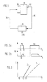
- Figure 1 shows a schematic representation of a device for performing the method according to claim 1.
- Figure 2 the control pulses for the pilot injection TV and the main injection TH are shown.
- Figure 3 shows the relationship between the duration of the drive pulse T and the injected fuel quantity QK.
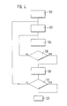
- a flow chart to explain the method is shown in FIG. 4.
- Figure 1 shows essential parts of a device for fuel injection into an internal combustion engine.
- the internal combustion engine 10 receives a certain amount of fuel from the fuel pump 30.
- Various sensors 40 record measured values 15 which characterize the operating state of the internal combustion engine and pass them to a control unit 20.
- the control unit 20 calculates, based on the measured values 15 and further variables 25, control pulses 35 with which the fuel pump 30 is acted upon.
- the internal combustion engine 10 is a self-igniting internal combustion engine.
- the control unit 20 calculates the amount of fuel to be injected into the internal combustion engine 10 in a known manner. This calculation is carried out depending on various measured values 15, e.g. Speed, engine temperature, actual start of injection and possibly other variables 25 that characterize the operating state of the internal combustion engine, these are e.g. the position of the accelerator pedal 25, the ambient air pressure.
- the control unit 20 then converts the desired fuel quantity into control pulses 35. These actuation pulses are then applied to the quantity-determining element of the fuel pump 30.
- a quantity-determining link e.g. serve a solenoid valve which is arranged so that the amount of fuel to be injected is determined by the opening or closing time of the solenoid valve.
- the solenoid valve is arranged, for example, in the high-pressure fuel pump in such a way that, during the delivery phase of the pump element, pressure builds up in the element space of the pump after the solenoid valve is closed, and the injection takes place automatically when a certain pressure value is exceeded. Opening the solenoid valve causes the Pressure in the element space and the injection is ended. By briefly closing and then opening the solenoid valve in the delivery phase of the pump element, a pre-injection can be achieved before the actual main injection.
- a separate high-pressure fuel pump with a solenoid valve that determines the fuel quantity to be injected can be provided for each cylinder, or a high-pressure fuel pump with a solenoid valve sequentially applies fuel to all cylinders.
- FIG. 2a shows a possible sequence of control pulses for a pre-injection TV and the subsequent main injection TH
- FIG. 2b shows the fuel quantity QK injected due to the control pulses shown in FIG. 2a over time t.
- FIGS. 2a and 2b show that the solenoid valve closes at time t1 and that fuel is injected after a short delay time t0. The solenoid valve opens at time t2 and the fuel supply ends.
- the control pulse for the pre-injection is significantly smaller than the control pulse for the main injection TH. Since solenoid valves can have different closing times for the same activation pulse, it can happen that different amounts of fuel are injected with the same duration of the activation pulse and otherwise the same operating parameters.
- control pulses for the pre-injection are usually very short, it can now occur that no pre-injection takes place for individual solenoid valves. On the other hand, however, it can also happen that the pilot injection becomes so large that the exhaust gas values of the internal combustion engine deteriorate.
- FIG. 3 shows the relationship between the duration of the drive pulse T and the injected fuel quantity Q for the solenoid valves 1 and 2.
- the solenoid valve 1 measures fuel in the event of a drive pulse of the time period T1.
- the Solenoid valves are supplied with a signal of duration T2, so pre-injection occurs only for solenoid valve 2, but not for solenoid valve 1.
- the aim of the method described below is to compensate for these variations. There are essentially two causes for this scattering, on the one hand there are tolerances in the manufacture of the solenoid valves and on the other hand there are signs of aging in the injection device. This process is particularly important in pump-nozzle systems.
- a method to compensate for these variations is now to be described with the aid of the flow chart of FIG.
- This method is not only limited to solenoid valve controlled fuel pumps, it can also be transferred to other electrically controlled signal boxes for high pressure fuel pumps at any time.
- a first step 100 it is checked whether the internal combustion engine is in an operating state in which the method can be carried out. These are preferably stationary operating points. However, it is also possible to initialize the process by means of a signal from an external control device. This is the case if the procedure is to be carried out in the factory by the engine manufacturer or as part of maintenance and possibly to be retained as the basic setting.
- the duration of the drive pulse is set to such a small value T0 that there is certainly no pre-injection.
- the drive pulses for the main injection are kept at a constant value in the following.
- the duration of the control pulse for the pre-injection is increased.
- the feedback signals like the operating parameters, are detected by suitable sensors 40. As feedback signals one or a combination of the signals from different sensors can be used in a particularly advantageous manner.
- Suitable sensors are sensors which detect the duration of the spray, the element pressure, the combustion chamber pressure, the engine structure-borne noise, the airborne noise, or a light signal in the combustion chamber. Possibly. the signals must be viewed in correlation with the control signal of the pilot injection. With a corresponding number of sensors, it is possible to consider each solenoid valve separately. If there is no feedback signal, the duration of the control pulse is increased further until a feedback signal is present. In the presence of a feedback signal, the duration of the actuation pulse is permanently stored 108 as an adjustment signal.
- the query unit 110 causes the procedure to be carried out for all cylinders. In step 120, the system jumps back to the main program for controlling the internal combustion engine, which is known per se.
- the procedure is carried out once in the factory at the engine manufacturer or as part of maintenance and is retained as the basic setting. Drifts over the term are compensated for in a controlled manner, depending on e.g. of the runtime weighted with speed and load. In operation, this procedure is carried out at stationary operating points. The adjustment signals are then used in the subsequent injection processes to adaptively improve the control of the pre-injection.
- the values determined with the aid of the method can be stored in a particularly advantageous manner in a map of load and speed and are then available for each pre-injection.
Landscapes
- Engineering & Computer Science (AREA)
- Chemical & Material Sciences (AREA)
- Combustion & Propulsion (AREA)
- Mechanical Engineering (AREA)
- General Engineering & Computer Science (AREA)
- Electrical Control Of Air Or Fuel Supplied To Internal-Combustion Engine (AREA)
- Combined Controls Of Internal Combustion Engines (AREA)
- Fuel-Injection Apparatus (AREA)
Applications Claiming Priority (2)
| Application Number | Priority Date | Filing Date | Title |
|---|---|---|---|
| DE3929747 | 1989-09-07 | ||
| DE3929747A DE3929747A1 (de) | 1989-09-07 | 1989-09-07 | Verfahren und einrichtung zum steuern der kraftstoffeinspritzung |
Publications (2)
| Publication Number | Publication Date |
|---|---|
| EP0416265A1 true EP0416265A1 (fr) | 1991-03-13 |
| EP0416265B1 EP0416265B1 (fr) | 1992-12-30 |
Family
ID=6388831
Family Applications (1)
| Application Number | Title | Priority Date | Filing Date |
|---|---|---|---|
| EP90114347A Expired - Lifetime EP0416265B1 (fr) | 1989-09-07 | 1990-07-26 | Procédé et appareil pour commander l'injection de carburant |
Country Status (4)
| Country | Link |
|---|---|
| US (1) | US5070836A (fr) |
| EP (1) | EP0416265B1 (fr) |
| JP (1) | JP3236915B2 (fr) |
| DE (2) | DE3929747A1 (fr) |
Cited By (13)
| Publication number | Priority date | Publication date | Assignee | Title |
|---|---|---|---|---|
| FR2720787A1 (fr) * | 1994-06-06 | 1995-12-08 | Renault Vehicules Ind | Procédé et dispositif de détermination des paramètres spécifiques des injecteurs d'un moteur à combustion, notamment d'un moteur diesel à pré-injection. |
| EP1450029A1 (fr) * | 2003-02-21 | 2004-08-25 | Delphi Technologies, Inc. | Méthode pour adapter de impulsions électriques pour commander un injecteur |
| FR2852360A1 (fr) * | 2003-03-13 | 2004-09-17 | Bosch Gmbh Robert | Procede de detection d'une valeur de decalage individuelle d'une grandeur electrique pour commander un injecteur d'un moteur a combustion interne |
| FR2864840A1 (fr) * | 2004-01-07 | 2005-07-08 | Bosch Gmbh Robert | Procede et dispositif de gestion d'un moteur a combustion interne |
| EP1813796A3 (fr) * | 2006-01-26 | 2007-12-19 | Delphi Technologies, Inc. | Contrôleur et procédé de contrôle pour une unité de contrôle de moteur |
| WO2008049704A1 (fr) * | 2006-10-25 | 2008-05-02 | Robert Bosch Gmbh | Procédé de détermination du diagramme caractéristique de la quantité d'injection au moyen de la grandeur électrique d'une soupape d'injection commandée électriquement |
| DE102008054409A1 (de) | 2008-12-09 | 2010-06-10 | Robert Bosch Gmbh | Verfahren und Vorrichtung zur Steuerung einer Brennkraftmaschine |
| FR2952120A1 (fr) * | 2009-11-02 | 2011-05-06 | Ems Concept | Dispositif de moteur pneumatique a injection pilotee par avance |
| EP2453124A1 (fr) * | 2010-11-16 | 2012-05-16 | Delphi Technologies Holding S.à.r.l. | Procédé permettant de déterminer les paramètres d'injection d'un injecteur |
| DE102013206600A1 (de) * | 2013-04-12 | 2014-10-16 | Continental Automotive Gmbh | Einspritzsystem zum Einspritzen von Kraftstoff in eine Brennkraftmaschine und Regelverfahren für ein solches Einspritzsystem |
| DE102014209194A1 (de) | 2014-05-15 | 2015-11-19 | Robert Bosch Gmbh | Verfahren und Vorrichtung zur Steuerung einer Brennkraftmaschine |
| US9435305B2 (en) | 2013-04-26 | 2016-09-06 | Continental Automotive Gmbh | Valve assembly for an injection valve and injection valve |
| US10746124B2 (en) | 2013-04-25 | 2020-08-18 | Continental Automotive Gmbh | Method for adapting an injection quantity |
Families Citing this family (47)
| Publication number | Priority date | Publication date | Assignee | Title |
|---|---|---|---|---|
| US5325837A (en) * | 1992-11-19 | 1994-07-05 | Robert Bosch Gmbh | Fuel injection apparatus for internal combustion engines |
| DE4312587C2 (de) * | 1993-04-17 | 2002-08-01 | Bosch Gmbh Robert | Verfahren und Vorrichtung zur Steuerung eines Kraftstoffeinspritzsystems |
| DE4411789C2 (de) * | 1994-04-06 | 2003-12-11 | Bosch Gmbh Robert | Verfahren und Vorrichtung zur Steuerung der Kraftstoffzumessung in eine Brennkraftmaschine |
| FR2754015B1 (fr) * | 1996-09-27 | 1998-10-30 | Inst Francais Du Petrole | Procede de controle de la quantite de carburant injecte dans un moteur diesel |
| DE19717493A1 (de) * | 1997-04-25 | 1998-10-29 | Bosch Gmbh Robert | Kraftstoffeinspritzsystem |
| US5986871A (en) * | 1997-11-04 | 1999-11-16 | Caterpillar Inc. | Method of operating a fuel injector |
| US6021754A (en) * | 1997-12-19 | 2000-02-08 | Caterpillar Inc. | Method and apparatus for dynamically calibrating a fuel injector |
| DE19809173A1 (de) | 1998-03-04 | 1999-09-09 | Bosch Gmbh Robert | Verfahren und Vorrichtung zum Steuern der Kraftstoffeinspritzung |
| US6289871B1 (en) * | 1998-03-06 | 2001-09-18 | Caterpillar Inc. | Method for achieving minimum liquid pilot fuel delivery to each cylinder of a dual fuel engine while operating in a dual fuel mode |
| US6116209A (en) * | 1998-05-27 | 2000-09-12 | Diesel Technology Company | Method of utilization of valve bounce in a solenoid valve controlled fuel injection system |
| DE19844746C1 (de) * | 1998-09-29 | 2000-04-20 | Siemens Ag | Verfahren und Vorrichtung zum Detektieren einer Voreinspritzung bei einer Brennkraftmaschine |
| JP3054702B2 (ja) * | 1998-11-10 | 2000-06-19 | 京都工芸繊維大学長 | 含芳香族ポリエステルの分解方法、含芳香族ポリエステル繊維の減量加工方法、含芳香族ポリエステル繊維および含芳香族ポリエステルの分解菌 |
| DE19917772B4 (de) * | 1999-04-20 | 2014-09-11 | Caterpillar Energy Solutions Gmbh | Ventilspielüberwachungseinrichtung |
| DE19931823B4 (de) * | 1999-07-08 | 2009-02-12 | Robert Bosch Gmbh | Verfahren und Vorrichtung zur Steuerung einer Brennkraftmaschine |
| DE19945618B4 (de) * | 1999-09-23 | 2017-06-08 | Robert Bosch Gmbh | Verfahren und Vorrichtung zur Steuerung eines Kraftstoffzumeßsystems einer Brennkraftmaschine |
| JP3867468B2 (ja) * | 2000-03-14 | 2007-01-10 | いすゞ自動車株式会社 | コモンレール式燃料噴射装置 |
| US6415762B1 (en) | 2000-07-13 | 2002-07-09 | Caterpillar Inc. | Accurate deliver of total fuel when two injection events are closely coupled |
| US6371077B1 (en) | 2000-07-13 | 2002-04-16 | Caterpillar Inc. | Waveform transitioning method and apparatus for multi-shot fuel systems |
| US6705277B1 (en) | 2000-07-13 | 2004-03-16 | Caterpillar Inc | Method and apparatus for delivering multiple fuel injections to the cylinder of an engine wherein the pilot fuel injection occurs during the intake stroke |
| US6467452B1 (en) | 2000-07-13 | 2002-10-22 | Caterpillar Inc | Method and apparatus for delivering multiple fuel injections to the cylinder of an internal combustion engine |
| US6363315B1 (en) | 2000-07-13 | 2002-03-26 | Caterpillar Inc. | Apparatus and method for protecting engine electronic circuitry from thermal damage |
| US6363314B1 (en) | 2000-07-13 | 2002-03-26 | Caterpillar Inc. | Method and apparatus for trimming a fuel injector |
| US6386176B1 (en) | 2000-07-13 | 2002-05-14 | Caterpillar Inc. | Method and apparatus for determining a start angle for a fuel injection associated with a fuel injection signal |
| US6480781B1 (en) | 2000-07-13 | 2002-11-12 | Caterpillar Inc. | Method and apparatus for trimming an internal combustion engine |
| US6453874B1 (en) | 2000-07-13 | 2002-09-24 | Caterpillar Inc. | Apparatus and method for controlling fuel injection signals during engine acceleration and deceleration |
| US6606974B1 (en) | 2000-07-13 | 2003-08-19 | Caterpillar Inc | Partitioning of a governor fuel output into three separate fuel quantities in a stable manner |
| US6390082B1 (en) | 2000-07-13 | 2002-05-21 | Caterpillar Inc. | Method and apparatus for controlling the current level of a fuel injector signal during sudden acceleration |
| US6450149B1 (en) | 2000-07-13 | 2002-09-17 | Caterpillar Inc. | Method and apparatus for controlling overlap of two fuel shots in multi-shot fuel injection events |
| US6516773B2 (en) | 2001-05-03 | 2003-02-11 | Caterpillar Inc | Method and apparatus for adjusting the injection current duration of each fuel shot in a multiple fuel injection event to compensate for inherent injector delay |
| US6516783B2 (en) | 2001-05-15 | 2003-02-11 | Caterpillar Inc | Camshaft apparatus and method for compensating for inherent injector delay in a multiple fuel injection event |
| DE10159016A1 (de) | 2001-12-01 | 2003-06-18 | Bosch Gmbh Robert | Verfahren und Vorrichtung zur Steuerung einer Brennkraftmaschine |
| FR2838775B1 (fr) * | 2002-04-17 | 2006-11-24 | Peugeot Citroen Automobiles Sa | Moteur diesel comportant un dispositif de controle du debit d'injection de carburant |
| DE10229019A1 (de) * | 2002-06-28 | 2004-01-29 | Robert Bosch Gmbh | Verfahren zur Steuerung eines Kraftstoffzumeßsystems einer Brennkraftmaschine |
| DE10254844A1 (de) | 2002-11-25 | 2004-06-03 | Robert Bosch Gmbh | Verfahren und Vorrichtung zum Betrieb eines Einspritzsystems einer Brennkraftmaschine |
| DE10257686A1 (de) | 2002-12-10 | 2004-07-15 | Siemens Ag | Verfahren zum Anpassen der Charakteristik eines Einspritzventils |
| FR2859282B1 (fr) * | 2003-09-03 | 2005-12-23 | Peugeot Citroen Automobiles Sa | Systeme de supervision du recalage d'au moins un parametre de controle du fonctionnement d'un moteur |
| DE10343759B4 (de) * | 2003-09-22 | 2015-01-15 | Robert Bosch Gmbh | Verfahren und Vorrichtung zur Bestimmung der Abweichung der tatsächlichen Einspritzmenge von einer berechneten Referenzeinspritzmenge eines Kraftstoffeinspritzsystems |
| JP4428201B2 (ja) * | 2004-11-01 | 2010-03-10 | 株式会社デンソー | 蓄圧式燃料噴射装置 |
| DE102006019317A1 (de) * | 2005-07-14 | 2007-01-25 | Robert Bosch Gmbh | Zur Dosierung von Kraftstoff zu Brennräumen eines Verbrennungsmotors dienendes Verfahren und Steuergerät |
| DE102006004738B4 (de) * | 2006-02-02 | 2020-04-09 | Volkswagen Ag | Verfahren zum Betreiben einer Brennkraftmaschine |
| DE102006015968B3 (de) * | 2006-04-05 | 2007-11-08 | Siemens Ag | Adaptionsverfahren und Adaptionsvorrichtung einer Einspritzanlage einer Brennkraftmaschine |
| DE102007057445A1 (de) | 2007-11-29 | 2009-06-04 | Robert Bosch Gmbh | Verfahren zum Betreiben eines Kraftstoffsystems einer Brennkraftmaschine und Kraftstoffsystem für eine Brennkraftmaschine |
| DE102011005773A1 (de) * | 2011-03-18 | 2012-01-19 | Continental Automotive Gmbh | Verfahren und Vorrichtung zum Steuern eines Einspritzventils zum Zumessen von Kraftstoff für eine Brennkraftmaschine |
| JP5648646B2 (ja) * | 2012-03-21 | 2015-01-07 | 株式会社デンソー | 燃料噴射制御装置 |
| EP2685074B1 (fr) * | 2012-07-13 | 2018-04-18 | Delphi Automotive Systems Luxembourg SA | Contrôle d'injection de carburant pour moteur à combustion interne |
| DE102013225152A1 (de) | 2013-12-06 | 2015-06-11 | Robert Bosch Gmbh | Verfahren zur Kalibrierung einer Hochdruckspeicher-Einspritzanlage einer Verbrennungskraftmaschine |
| DE102017214397A1 (de) | 2017-08-18 | 2019-02-21 | Robert Bosch Gmbh | Verfahren zur Steuerung einer Brennkraftmaschine |
Citations (4)
| Publication number | Priority date | Publication date | Assignee | Title |
|---|---|---|---|---|
| US3982519A (en) * | 1975-05-27 | 1976-09-28 | Ford Motor Company | Electronic-fuel-injection-system enrichment circuit for use during engine cranking |
| EP0078987A2 (fr) * | 1981-11-11 | 1983-05-18 | Nissan Motor Co., Ltd. | Système de détection d'injection de carburant pour moteur diesel |
| DE3430551A1 (de) * | 1984-08-20 | 1986-02-27 | Robert Bosch Gmbh, 7000 Stuttgart | Einrichtung zur aenderung von gespeicherten kenngroessen in elektronischen steuergeraeten fuer insbesondere brennkraftmaschinen |
| US4790277A (en) * | 1987-06-03 | 1988-12-13 | Ford Motor Company | Self-adjusting fuel injection system |
Family Cites Families (6)
| Publication number | Priority date | Publication date | Assignee | Title |
|---|---|---|---|---|
| US4579096A (en) * | 1983-12-08 | 1986-04-01 | Toyota Jidosha Kabushiki Kaisha | Diesel fuel injection pump with electromagnetic fuel spilling valve having pilot valve providing high responsiveness |
| JPH086627B2 (ja) * | 1985-06-04 | 1996-01-29 | 株式会社日本自動車部品総合研究所 | ディーゼルエンジンの燃料噴射制御方法及び制御装置 |
| JPS62206238A (ja) * | 1986-03-05 | 1987-09-10 | Nippon Denso Co Ltd | 燃料噴射ポンプのパイロツト噴射装置 |
| JPS635140A (ja) * | 1986-06-24 | 1988-01-11 | Diesel Kiki Co Ltd | 燃料噴射ポンプの噴射制御方法 |
| DE3629751C2 (de) * | 1986-09-01 | 1998-07-02 | Bosch Gmbh Robert | Voreinspritzvorrichtung für Brennkraftmaschinen |
| DE3715614A1 (de) * | 1987-05-11 | 1988-11-24 | Bosch Gmbh Robert | Kraftstoffeinspritzpumpe |
-
1989
- 1989-09-07 DE DE3929747A patent/DE3929747A1/de not_active Withdrawn
-
1990
- 1990-07-26 EP EP90114347A patent/EP0416265B1/fr not_active Expired - Lifetime
- 1990-07-26 DE DE9090114347T patent/DE59000690D1/de not_active Expired - Lifetime
- 1990-08-29 JP JP22545490A patent/JP3236915B2/ja not_active Expired - Lifetime
- 1990-09-05 US US07/577,754 patent/US5070836A/en not_active Expired - Lifetime
Patent Citations (4)
| Publication number | Priority date | Publication date | Assignee | Title |
|---|---|---|---|---|
| US3982519A (en) * | 1975-05-27 | 1976-09-28 | Ford Motor Company | Electronic-fuel-injection-system enrichment circuit for use during engine cranking |
| EP0078987A2 (fr) * | 1981-11-11 | 1983-05-18 | Nissan Motor Co., Ltd. | Système de détection d'injection de carburant pour moteur diesel |
| DE3430551A1 (de) * | 1984-08-20 | 1986-02-27 | Robert Bosch Gmbh, 7000 Stuttgart | Einrichtung zur aenderung von gespeicherten kenngroessen in elektronischen steuergeraeten fuer insbesondere brennkraftmaschinen |
| US4790277A (en) * | 1987-06-03 | 1988-12-13 | Ford Motor Company | Self-adjusting fuel injection system |
Non-Patent Citations (6)
| Title |
|---|
| PATENT ABSTRACTS OF JAPAN vol. 10, no. 37 (M-453) 14 Februar 1986, & JP-A-60 190637 (NIPPON DENSO K.K.) 28 September 1985, * |
| PATENT ABSTRACTS OF JAPAN vol. 12, no. 197 (M-706) 08 Juni 1988, & JP-A-63 005139 (NIPPON SOKEN INC.) 11 Januar 1988, * |
| PATENT ABSTRACTS OF JAPAN vol. 13, no. 225 (M-830) 25 Mai 1989, & JP-A-01 041643 (NIPPON DENSO CO.LTD.) 13 Februar 1989, * |
| PATENT ABSTRACTS OF JAPAN vol. 9, no. 286 (M-429) 13 November 1985, & JP-A-60 125753 (TOYOTA JIDOSHA K.K.) 05 Juli 1985, * |
| PATENT ABSTRACTS OF JAPAN vol. 9, no. 333 (M-443) 27 Dezember 1985, & JP-A-60 164661 (HITACHI LTD.) 27 August 1985, * |
| RESEARCH DISCLOSURE. no. 289, Mai 1988, HAVANT GB Seite 292 ,Disclosure Nr 28942: "Fuel Injector With Programmed Calibration" * |
Cited By (20)
| Publication number | Priority date | Publication date | Assignee | Title |
|---|---|---|---|---|
| FR2720787A1 (fr) * | 1994-06-06 | 1995-12-08 | Renault Vehicules Ind | Procédé et dispositif de détermination des paramètres spécifiques des injecteurs d'un moteur à combustion, notamment d'un moteur diesel à pré-injection. |
| EP0686762A1 (fr) * | 1994-06-06 | 1995-12-13 | Renault Vehicules Industriels | Procédé et dispositif de détermination des paramètres spécifiques des injecteurs d'un moteur à combustion, notamment Diesel à pré-injection |
| EP1450029A1 (fr) * | 2003-02-21 | 2004-08-25 | Delphi Technologies, Inc. | Méthode pour adapter de impulsions électriques pour commander un injecteur |
| FR2851616A1 (fr) * | 2003-02-21 | 2004-08-27 | Delphi Technologies | Procede de reglage de l'impulsion electrique de commande d'un injecteur |
| FR2852360A1 (fr) * | 2003-03-13 | 2004-09-17 | Bosch Gmbh Robert | Procede de detection d'une valeur de decalage individuelle d'une grandeur electrique pour commander un injecteur d'un moteur a combustion interne |
| FR2864840A1 (fr) * | 2004-01-07 | 2005-07-08 | Bosch Gmbh Robert | Procede et dispositif de gestion d'un moteur a combustion interne |
| EP1813796A3 (fr) * | 2006-01-26 | 2007-12-19 | Delphi Technologies, Inc. | Contrôleur et procédé de contrôle pour une unité de contrôle de moteur |
| WO2008049704A1 (fr) * | 2006-10-25 | 2008-05-02 | Robert Bosch Gmbh | Procédé de détermination du diagramme caractéristique de la quantité d'injection au moyen de la grandeur électrique d'une soupape d'injection commandée électriquement |
| DE102008054409A1 (de) | 2008-12-09 | 2010-06-10 | Robert Bosch Gmbh | Verfahren und Vorrichtung zur Steuerung einer Brennkraftmaschine |
| FR2952120A1 (fr) * | 2009-11-02 | 2011-05-06 | Ems Concept | Dispositif de moteur pneumatique a injection pilotee par avance |
| EP2453124A1 (fr) * | 2010-11-16 | 2012-05-16 | Delphi Technologies Holding S.à.r.l. | Procédé permettant de déterminer les paramètres d'injection d'un injecteur |
| WO2012066044A1 (fr) * | 2010-11-16 | 2012-05-24 | Delphi Technologies Holding S.À.R.L. | Procédé de détermination de paramètres d'injection pour un injecteur |
| DE102013206600A1 (de) * | 2013-04-12 | 2014-10-16 | Continental Automotive Gmbh | Einspritzsystem zum Einspritzen von Kraftstoff in eine Brennkraftmaschine und Regelverfahren für ein solches Einspritzsystem |
| DE102013206600B4 (de) * | 2013-04-12 | 2015-08-06 | Continental Automotive Gmbh | Einspritzsystem zum Einspritzen von Kraftstoff in eine Brennkraftmaschine und Regelverfahren für ein solches Einspritzsystem |
| CN105074180A (zh) * | 2013-04-12 | 2015-11-18 | 大陆汽车有限公司 | 用于喷射燃料到内燃机中的方法和装置 |
| CN105074180B (zh) * | 2013-04-12 | 2017-12-29 | 大陆汽车有限公司 | 用于喷射燃料到内燃机中的方法和装置 |
| US9903294B2 (en) | 2013-04-12 | 2018-02-27 | Continental Automotive Gmbh | Method and device for injecting fuel into an internal combustion engine |
| US10746124B2 (en) | 2013-04-25 | 2020-08-18 | Continental Automotive Gmbh | Method for adapting an injection quantity |
| US9435305B2 (en) | 2013-04-26 | 2016-09-06 | Continental Automotive Gmbh | Valve assembly for an injection valve and injection valve |
| DE102014209194A1 (de) | 2014-05-15 | 2015-11-19 | Robert Bosch Gmbh | Verfahren und Vorrichtung zur Steuerung einer Brennkraftmaschine |
Also Published As
| Publication number | Publication date |
|---|---|
| US5070836A (en) | 1991-12-10 |
| JPH03100350A (ja) | 1991-04-25 |
| DE59000690D1 (de) | 1993-02-11 |
| DE3929747A1 (de) | 1991-03-14 |
| JP3236915B2 (ja) | 2001-12-10 |
| EP0416265B1 (fr) | 1992-12-30 |
Similar Documents
| Publication | Publication Date | Title |
|---|---|---|
| EP0416265B1 (fr) | Procédé et appareil pour commander l'injection de carburant | |
| EP0416270B1 (fr) | Procédé et dispositif pour commander et régler un moteur à auto-allumage | |
| DE4312587C2 (de) | Verfahren und Vorrichtung zur Steuerung eines Kraftstoffeinspritzsystems | |
| DE102008043165B4 (de) | Verfahren und Vorrichtung zur Kalibrierung der Voreinspritzmenge einer Brennkraftmaschine, insbesondere eines Kraftfahrzeugs | |
| EP0940571B1 (fr) | Procédé et dispositif pour contrôler l'injection de carburant | |
| DE102010040283B3 (de) | Verfahren zur Regelung der Einspritzmenge eines Piezoinjektors eines Kraftstoffeinspritzsystems | |
| DE19945618A1 (de) | Verfahren und Vorrichtung zur Steuerung eines Kraftstoffzumeßsystems einer Brennkraftmaschine | |
| DE19536110A1 (de) | Verfahren und Vorrichtung zur Steuerung einer Brennkraftmaschine | |
| DE10143501C1 (de) | Verfahren zum Ansteuern eines piezobetriebenen Kraftstoff-Einspritzventils | |
| DE102008040227A1 (de) | Verfahren und Vorrichtung zur Druckwellenkompensation bei zeitlich aufeinander folgenden Einspritzungen in einem Einspritzsystem einer Brennkraftmaschine | |
| DE10305523A1 (de) | Verfahren und Vorrichtung zur Nullmengenkalibrierung eines Kraftstoffeinspritzsystems eines Kraftfahrzeuges im Fahrbetrieb | |
| DE102015217945A1 (de) | Vorrichtung zur Steuerung von wenigstens einem schaltbaren Ventil | |
| DE102011089296A1 (de) | Verfahren und Vorrichtung zur Kalibrierung eines Kraftstoffzumesssystems eines Kraftfahrzeugs | |
| DE19931823B4 (de) | Verfahren und Vorrichtung zur Steuerung einer Brennkraftmaschine | |
| DE10123035A1 (de) | Verfahren und Vorrichtung zur Steuerung einer Brennkraftmaschine | |
| WO1989011034A1 (fr) | Syteme de commande pour moteurs diesel | |
| DE4322270B4 (de) | Verfahren und Vorrichtung zur Steuerung einer Brennkraftmaschine | |
| EP1567758B1 (fr) | Procede et dispositif pour faire fonctionner un systeme d'injection d'un moteur a combustion interne | |
| DE102005058445B3 (de) | Verfahren zur Ermittlung einer in einen Zylinder einer Brennkraftmaschine mit einer Common-Rail-Einspritzanlage eingespritzten Kraftstoffmemge und Mittel zur Durchführung des Verfahrens | |
| DE102008005154A1 (de) | Verfahren und Vorrichtung zur Überwachung einer Motorsteuereinheit | |
| DE10315817A1 (de) | Verfahren und Vorrichtung zum Betrieb eines eine Mengenausgleichsregelung aufweisenden Einspritzsystems einer Brennkraftmaschine an der thermodynamischen Wirkgrenze für Voreinspritzungen | |
| DE102012212195A1 (de) | Verfahren zum Betreiben einer Brennkraftmaschine | |
| DE102008043575A1 (de) | Verfahren und Vorrichtung zur Kleinstmengenkalibrierung der Einspritzmenge von Teileinspritzungen in einer Brennkraftmaschine, insbesondere eines Kraftfahrzeugs | |
| DE102016217415A1 (de) | Verfahren und Vorrichtung zum Kalibrieren von Kraftstoffinjektoren mit Leerhub | |
| DE4204091A1 (de) | Verfahren und einrichtung zur steuerung eines magnetventilgesteuerten kraftstoffzumesssystems |
Legal Events
| Date | Code | Title | Description |
|---|---|---|---|
| PUAI | Public reference made under article 153(3) epc to a published international application that has entered the european phase |
Free format text: ORIGINAL CODE: 0009012 |
|
| AK | Designated contracting states |
Kind code of ref document: A1 Designated state(s): DE FR GB |
|
| 17P | Request for examination filed |
Effective date: 19910904 |
|
| 17Q | First examination report despatched |
Effective date: 19920110 |
|
| RAP3 | Party data changed (applicant data changed or rights of an application transferred) |
Owner name: ROBERT BOSCH GMBH |
|
| GRAA | (expected) grant |
Free format text: ORIGINAL CODE: 0009210 |
|
| AK | Designated contracting states |
Kind code of ref document: B1 Designated state(s): DE FR GB |
|
| GBT | Gb: translation of ep patent filed (gb section 77(6)(a)/1977) |
Effective date: 19921229 |
|
| REF | Corresponds to: |
Ref document number: 59000690 Country of ref document: DE Date of ref document: 19930211 |
|
| ET | Fr: translation filed | ||
| PLBE | No opposition filed within time limit |
Free format text: ORIGINAL CODE: 0009261 |
|
| STAA | Information on the status of an ep patent application or granted ep patent |
Free format text: STATUS: NO OPPOSITION FILED WITHIN TIME LIMIT |
|
| 26N | No opposition filed | ||
| REG | Reference to a national code |
Ref country code: GB Ref legal event code: IF02 |
|
| PGFP | Annual fee paid to national office [announced via postgrant information from national office to epo] |
Ref country code: FR Payment date: 20090720 Year of fee payment: 20 |
|
| PGFP | Annual fee paid to national office [announced via postgrant information from national office to epo] |
Ref country code: GB Payment date: 20090724 Year of fee payment: 20 |
|
| PGFP | Annual fee paid to national office [announced via postgrant information from national office to epo] |
Ref country code: DE Payment date: 20090918 Year of fee payment: 20 |
|
| REG | Reference to a national code |
Ref country code: GB Ref legal event code: PE20 Expiry date: 20100725 |
|
| PG25 | Lapsed in a contracting state [announced via postgrant information from national office to epo] |
Ref country code: GB Free format text: LAPSE BECAUSE OF EXPIRATION OF PROTECTION Effective date: 20100725 |
|
| PG25 | Lapsed in a contracting state [announced via postgrant information from national office to epo] |
Ref country code: DE Free format text: LAPSE BECAUSE OF EXPIRATION OF PROTECTION Effective date: 20100726 |