EP0416432A2 - A shaft body made of metal film and carbon fibers and method for manufacturing the same - Google Patents
A shaft body made of metal film and carbon fibers and method for manufacturing the same Download PDFInfo
- Publication number
- EP0416432A2 EP0416432A2 EP90116433A EP90116433A EP0416432A2 EP 0416432 A2 EP0416432 A2 EP 0416432A2 EP 90116433 A EP90116433 A EP 90116433A EP 90116433 A EP90116433 A EP 90116433A EP 0416432 A2 EP0416432 A2 EP 0416432A2
- Authority
- EP
- European Patent Office
- Prior art keywords
- metal film
- shaft body
- film
- carbon fiber
- resin
- Prior art date
- Legal status (The legal status is an assumption and is not a legal conclusion. Google has not performed a legal analysis and makes no representation as to the accuracy of the status listed.)
- Withdrawn
Links
Images



Classifications
-
- B—PERFORMING OPERATIONS; TRANSPORTING
- B32—LAYERED PRODUCTS
- B32B—LAYERED PRODUCTS, i.e. PRODUCTS BUILT-UP OF STRATA OF FLAT OR NON-FLAT, e.g. CELLULAR OR HONEYCOMB, FORM
- B32B1/00—Layered products having a non-planar shape
- B32B1/08—Tubular products
-
- B—PERFORMING OPERATIONS; TRANSPORTING
- B32—LAYERED PRODUCTS
- B32B—LAYERED PRODUCTS, i.e. PRODUCTS BUILT-UP OF STRATA OF FLAT OR NON-FLAT, e.g. CELLULAR OR HONEYCOMB, FORM
- B32B15/00—Layered products comprising a layer of metal
- B32B15/04—Layered products comprising a layer of metal comprising metal as the main or only constituent of a layer, which is next to another layer of the same or of a different material
- B32B15/08—Layered products comprising a layer of metal comprising metal as the main or only constituent of a layer, which is next to another layer of the same or of a different material of synthetic resin
-
- B—PERFORMING OPERATIONS; TRANSPORTING
- B32—LAYERED PRODUCTS
- B32B—LAYERED PRODUCTS, i.e. PRODUCTS BUILT-UP OF STRATA OF FLAT OR NON-FLAT, e.g. CELLULAR OR HONEYCOMB, FORM
- B32B15/00—Layered products comprising a layer of metal
- B32B15/14—Layered products comprising a layer of metal next to a fibrous or filamentary layer
-
- B—PERFORMING OPERATIONS; TRANSPORTING
- B32—LAYERED PRODUCTS
- B32B—LAYERED PRODUCTS, i.e. PRODUCTS BUILT-UP OF STRATA OF FLAT OR NON-FLAT, e.g. CELLULAR OR HONEYCOMB, FORM
- B32B7/00—Layered products characterised by the relation between layers; Layered products characterised by the relative orientation of features between layers, or by the relative values of a measurable parameter between layers, i.e. products comprising layers having different physical, chemical or physicochemical properties; Layered products characterised by the interconnection of layers
- B32B7/04—Interconnection of layers
- B32B7/12—Interconnection of layers using interposed adhesives or interposed materials with bonding properties
-
- B—PERFORMING OPERATIONS; TRANSPORTING
- B62—LAND VEHICLES FOR TRAVELLING OTHERWISE THAN ON RAILS
- B62K—CYCLES; CYCLE FRAMES; CYCLE STEERING DEVICES; RIDER-OPERATED TERMINAL CONTROLS SPECIALLY ADAPTED FOR CYCLES; CYCLE AXLE SUSPENSIONS; CYCLE SIDE-CARS, FORECARS, OR THE LIKE
- B62K19/00—Cycle frames
- B62K19/02—Cycle frames characterised by material or cross-section of frame members
- B62K19/16—Cycle frames characterised by material or cross-section of frame members the material being wholly or mainly of plastics
-
- B—PERFORMING OPERATIONS; TRANSPORTING
- B62—LAND VEHICLES FOR TRAVELLING OTHERWISE THAN ON RAILS
- B62K—CYCLES; CYCLE FRAMES; CYCLE STEERING DEVICES; RIDER-OPERATED TERMINAL CONTROLS SPECIALLY ADAPTED FOR CYCLES; CYCLE AXLE SUSPENSIONS; CYCLE SIDE-CARS, FORECARS, OR THE LIKE
- B62K21/00—Steering devices
- B62K21/12—Handlebars; Handlebar stems
-
- B—PERFORMING OPERATIONS; TRANSPORTING
- B32—LAYERED PRODUCTS
- B32B—LAYERED PRODUCTS, i.e. PRODUCTS BUILT-UP OF STRATA OF FLAT OR NON-FLAT, e.g. CELLULAR OR HONEYCOMB, FORM
- B32B2260/00—Layered product comprising an impregnated, embedded, or bonded layer wherein the layer comprises an impregnation, embedding, or binder material
- B32B2260/02—Composition of the impregnated, bonded or embedded layer
- B32B2260/021—Fibrous or filamentary layer
-
- B—PERFORMING OPERATIONS; TRANSPORTING
- B32—LAYERED PRODUCTS
- B32B—LAYERED PRODUCTS, i.e. PRODUCTS BUILT-UP OF STRATA OF FLAT OR NON-FLAT, e.g. CELLULAR OR HONEYCOMB, FORM
- B32B2260/00—Layered product comprising an impregnated, embedded, or bonded layer wherein the layer comprises an impregnation, embedding, or binder material
- B32B2260/04—Impregnation, embedding, or binder material
- B32B2260/046—Synthetic resin
-
- B—PERFORMING OPERATIONS; TRANSPORTING
- B32—LAYERED PRODUCTS
- B32B—LAYERED PRODUCTS, i.e. PRODUCTS BUILT-UP OF STRATA OF FLAT OR NON-FLAT, e.g. CELLULAR OR HONEYCOMB, FORM
- B32B2262/00—Composition or structural features of fibres which form a fibrous or filamentary layer or are present as additives
- B32B2262/10—Inorganic fibres
- B32B2262/106—Carbon fibres, e.g. graphite fibres
Definitions
- the present invention relates to a shaft body used for bicycles, motorcycles, automobiles, yachts, wind-surfing masts, etc. and a method for manufacturing the same and more particularly to shaft body obtained from a combination of metal films and carbon fibers and a method for manufacturing such a shaft body.
- the weight of the pipe becomes much heavier than a carbon fiber pipe itself. Even though the aluminum pipe is made thinner, thickness is limited as far as the existing aluminum pipes are used. Thus, it is unavoidable to reduce the weight. In addition, there is also a limitation to reducing the weight even though the inner diameter of the aluminum pipe is reduced as far as the existing aluminum pipes are used.
- the resin is thermally hardened by heating the prepreg.
- the inner aluminum expands and the carbon fibers shrink; as a result, the carbon fibers are placed under an extreme tension. Accordingly, when the pipe is cooled, a severe stress concentration occurs in various portions of the carbon fibers, and a latent danger of carbon fiber breakage is created.
- the aluminum pipe is located inside the carbon fiber layer, an actual danger would be minimal, though the quality of the resulted pipe is severely compromised.
- the technical problem of the present invention is to eliminate the drawbacks in prior art pipes used for frames for bicycles, etc.
- a shaft body can be obtained by rolling up and fixing, at least, a metal film and carbon fibers so as to form a shaft body obtained from a combination of the metal film and carbon fiber fabric.
- a metal film such as an aluminum foil is employed and existing metal pipes such as aluminum pipes are not used at all.
- existing metal pipes such as aluminum pipes are not used at all.
- the internal diameter and thickness of the pipes are limited.
- the internal diameter of the resulting metal-film pipe can be different as desired by merely selecting core material having different outer diameters, and the thickness of the shaft can be freely adjusted by altering the number of wrappings and/or thickness of the metal film.
- the metal layer can be formed inexpensively and the weight of the metal layer can be lightened.
- the thickness and weight, which the shaft body will have after the formation of the carbon layer can easily be adjusted.
- the method of the present invention can contribute a cost reduction and meet a small-scale production of various different types of shaft bodies.
- the thermal expansion of the metal film toward the outside is extremely small compared to that of metal pipes.
- the shaft body in the prior art is formed by metal pipe and carbon fiber fabric, e. g. the metal pipe is steel pipe or aluminum pipe. These pipes are rigid bodies. Then thermal expansion of the pipes tends toward the outside of the pipe.
- the shaft body in this invention is formed by metal film and carbon fiber fabric.
- this metal film is aluminum foil or metal wrapping film. This film is very transformably or distortably because of its thinness. So the thermal expansion tends toward the outside, inside or horizontal for the surface of the pipe. Accordingly, the effects giving for the carbon fiber fabric are less than the prior art.
- a stainless steel film, aluminum film, titanium film, chromium-molybdenum alloy film, etc. can be used as the metal film. Selection of the metal film depends on the intended use of the shaft body in view of different factors including weights, corrosion resistance, malleability, costs, etc.
- a titanium film is probably the most desirable material to be used as the shafts for bicycle frames. Though the existing titanium pipes have not general utility and therefore such pipes are not mass-produced, according to the present invention, a shaft body can be formed with a titanium film.
- a prepreg formed by a carbon fiber fabric impregnated with a liquid-form resin is used.
- Such methods include, for example, (a) a method in which the metal film is first wrapped around a core, the prepreg is wrapped thereon and then this assembly is hardened, (b) a method in which the metal film and prepreg are laid together and then wrapped around a core, and (c) a method in which the metal film is rolled up to form a cylinder, a core is inserted into this cylinder, and then the prepreg is wrapped aroung this assembly and hardened.
- the shaft body of the present invention is obtained as described above, the metal film (as a result of its malleability) can absorb and disperse any sudden shock received by the carbon fibers is prevented. Accordingly, the shock resistance and breaking strength of the shaft body are remarkably increased, and the safety of bicycles, motorcycles, automobiles, etc. built with the shaft body of the present invention is greatly improved.
- the shaft body manufactured in accordance with the present invention can also be used as tennis rackets, golf clubs, fishing poles, furniture, etc.
- a hollow shaft body can be formed by removing the mandrel after the resin has hardened.
- Pipes with various cross-sectional shapes can be formed by selecting mandrels of different cross-sectional shapes such as circular, triangular, square, hexagonal, etc.
- the foam core can be used.
- the weight of the core will become almost zero and curved pipes such as those used as bicycle handlebars can be easily manufactured. More specifically, if a titanium film and a carbon fiber fabric are wrapped around the circumference of a core shaped in handlebar, a handlebar pipe which is the same as an ordinary steel handlebar can be manufactured. In other words, according to the present invention, straight pipes as well as bent pipes can be manufactured.
- Fig. 1 is a partially cross-sectional perspective view of a completed shaft body 2 in which a carbon layer 6 is laminated and fixed on the surface or circumference of a metal layer 4.
- Figs. 2(A) through 2(G) show a manufacturing process of the shaft body 2 of Fig. 1.
- Fig. 2(A) illustrates a metal film 2a with a thickness of 20 microns to 50 microns, which is appropriate for the shaft body of the present invention. It goes without saying that films of other thicknesses may be used. If the film is too thick, wrapping will become difficult; and if the film is too thin, the cost of the film will be increased.
- a titanium film is used as the metal film; however, depending on the intended use, it would be possible to use a stainless steel film, an aluminum film, a chromium-molybdenum film, etc.
- the features of light weight and good corrosion resistance, etc. of titanium can be utilized to a great advantage for bicycle pipes. Materials such as titanium alloys, etc. can also be used in addition to pure titanium.
- the metal film 2a is washed with water after its surface is being roughened by etching or honing.
- Fig. 2(B) illustrates a process in which an adhesive film 2b is bonded to one side of the metal film 2a. It would be possible to apply a coating of an adhesive agent instead of the adhesive film. Since the surface of the metal film 2a has been roughened in the previous step, the area of contact between the metal film 2a and the adhesive film or adhesive agent is increased. Thus, a very high adhesive strength is obtainable.
- Fig. 2(C) shows the wrapping process of the metal film around the circumference of a core (mandrel) 8.
- the metal film 2a is wrapped so that the adhesive film 2b is on the outside.
- the number of wrappings varies case by case basis, and it is advisable to use several wrappings.
- Fig. 2(D) shows the resulting metal layer 4 wrapped around the circumference of the core material 8. Though the thickness of the metal layer 4 can be set differently, 0.03 to 0.3 mm is the most appropriate.
- Fig. 2(E) illustrates a process in which a prepreg 6a is wrapped around the circumference of the metal layer 4. Since the outer surface of the metal layer 4 is an adhesive film, the prepreg 6a is strongly bonded to the adhesive film.
- the prepreg 6a is formed by impregnating a liquid resin into a carbon fiber fabric.
- This carbon fiber fabric is a cloth formed by weaving or knitting carbon fibers or a non-woven fabric of carbon fibers.
- thermosetting resins of thermoplastic resins may also be utilized.
- polyamides, aromatic polyamide, polybenzothiazole, polyethersulfone, polyaminobismaleimide, etc. may be used.
- the number of wrappings of the prepreg 6a may be selected as desired. In most cases, ten or less wrappings will be most appropriate.
- Fig. 2(F) shows a completed intermediate part 10 formed by wrapping the metal layer 4 and carbon layer 6 around the core 8.
- the intermediate part 10 When, in the next step, the intermediate part 10 is placed in an electric oven and heated, the adhesive film 2b and liquid-form resin are hardened, and the metal layer 4 and carbon layer 6 are tightly settled overall. Thus, an integral pipe body is obtained.
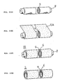
- Figs. 3(A) through 3(D) illustrate a second embodiment of the method of manufacturing a shaft body in accordance with the present invention.
- the metal film 2a and prepreg 6a are laid together or placed one on the other.
- the prepreg 6a is placed on the metal film 2a.
- this assembly is wrapped around a core B so as to form an intermediate part 10 wherein the metal film 2a and carbon fiber fabric are laminated in alternating layers.
- the intermediate part 10 is heated in an electric oven so that the resin is hardened, and the shaft body 2 is completed by removing the core 8.
- Figs. 4(A) through 4(D) illustrate a third embodiment of the present invention.
- the metal film 2a is rolled up to make a metal film cylinder 2c.
- a gap is left between the two ends of the cylindrical metal film 2a so that the gap becomes a slit 2d.
- Fig. 5(A) shows a cross section of the shaft body 2 of Fig. 1. From this figure, it can be easily seen that the carbon layer 6 is laminated on the metal layer 4.
- Figs. 5(B) through 5(D) illustrate the cross sections of the shaft bodies of other embodiments.
- Fig. 5(B) the carbon layer 6 is installed not only on the outside of the metal layer 4 but also on the inside thereof. Alternatively, it would be possible to install the metal layer 4 on the most outer surface and/or to install the metal layers 4 in plurality.
- Fig. 5(C) shows that the inside of the metal layer 4 is filled with a foam 12
- Fig. 5(D) shows a shaft body 2 having a square cross section as a result of use of a square core.
- Fig. 6 illustrates a bicycle handlebar 14.
- a foam is shaped into a bicycle handlebar and used as a core.
- a metal layer and carbon layer are formed on the outer surface of this foam by the same method as explained by way of Fig. 2, and the core remains in the shaft body without being removed. Since the core is made of a foam, the shaft body is extremely light.
- the handlebar 14 is formed with the core left inside.
- bent pipes can be formed as well as straight pipes.
- the present invention is not limited to the embodiments described above. Various modifications and design alterations, etc. are within the technical scope of the present invention as long as there is no departure from the technical spirit of the invention.
- shaft bodies are manufactured by laminating a carbon layer and a metal layer (a layer consisting of a metal film).
- a metal layer a layer consisting of a metal film.
- the brittleness of the carbon is compensated for the strength and malleability of the metal layer.
- the shock resistance and breaking strength are greatly improved.
- the shaft body which is light and extremely safe is manufactured which is utilized in a broad range of industrial fields including bicycles, motorcycles, automobiles, sport equipment, furniture, etc.
Landscapes
- Engineering & Computer Science (AREA)
- Mechanical Engineering (AREA)
- Laminated Bodies (AREA)
- Steering Devices For Bicycles And Motorcycles (AREA)
- Golf Clubs (AREA)
Abstract
Description
- The present invention relates to a shaft body used for bicycles, motorcycles, automobiles, yachts, wind-surfing masts, etc. and a method for manufacturing the same and more particularly to shaft body obtained from a combination of metal films and carbon fibers and a method for manufacturing such a shaft body.
- In recent years, bicycle competitions such as road races, triathlon events, mountain biking (ATB), etc. have become more and more popular. As bicycling becomes more popular and spreads to children and elderly people, a demand for lightening the bicycle frame as well as improvement in the safety in bicycle riding increases.
- In this trend, one of the techniques for lightening the bicycle weight is to replace steel pipes with aluminium pipes and even further with carbon fiber pipes. Recently revealed techniques decrease the weight of the bicycle dramatically by replacing various types of bicycle pipes, which make the bicycle body heavy, with carbon fiber pipes (CORP).
- Since carbon fiber pipes are strong and extremely light, such pipes are considered safe to be used in bicycles. However, when a partial breakage occurs in carbon fiber pipes as a result of an abrupt impact, there would be a danger that the carbon fiber pipes would break into pieces.
- Accordingly, it is necessary to endow carbon fiber pipes with the ability to absorb shocks before the point where the breakage occurs when such impacts are applied to the pipes. In order to achieve this, one type of pipe has been proposed. This pipe is made by wrapping a prepreg (formed by impregnating a resin into carbon fiber fabric) around an aluminum pipe, and then thermally hardening the resin in the prepreg so that an aluminum layer and carbon fiber layer are laminated on the pipe. In this pipe, the carbon fibers are reinforced and supported by the aluminum pipe so as to prevent the breakage caused by impacts.
- However, the above-mentioned two-layer pipe has drawbacks in spite of its general advantages.
- First, since the carbon fiber layer is laminated on the aluminum pipe, the weight of the pipe becomes much heavier than a carbon fiber pipe itself. Even though the aluminum pipe is made thinner, thickness is limited as far as the existing aluminum pipes are used. Thus, it is unavoidable to reduce the weight. In addition, there is also a limitation to reducing the weight even though the inner diameter of the aluminum pipe is reduced as far as the existing aluminum pipes are used.
- Furthermore, since the cost of the aluminum pipe is added to the cost of the carbon fibers, the pipe tends to be very expensive.
- The most serious problem with the above-described pipe is that the coefficient of linear expansion of aluminum is positive, while that of the carbon fibers is negative. In other words, when heated, aluminum undergoes thermal expansion, while the carbon fibers undergo thermal shrinkage.
- Furthermore, when the two-layer pipes described above are manufactured, the resin is thermally hardened by heating the prepreg. When this is performed, however, the inner aluminum expands and the carbon fibers shrink; as a result, the carbon fibers are placed under an extreme tension. Accordingly, when the pipe is cooled, a severe stress concentration occurs in various portions of the carbon fibers, and a latent danger of carbon fiber breakage is created. Of course, since the aluminum pipe is located inside the carbon fiber layer, an actual danger would be minimal, though the quality of the resulted pipe is severely compromised.
- Accordingly, the technical problem of the present invention is to eliminate the drawbacks in prior art pipes used for frames for bicycles, etc.
- The above problem is solved by the features as defined in claim 1.
- By means of the invention a shaft body can be obtained by rolling up and fixing, at least, a metal film and carbon fibers so as to form a shaft body obtained from a combination of the metal film and carbon fiber fabric.
- One of the most important features of the present invention is that a metal film such as an aluminum foil is employed and existing metal pipes such as aluminum pipes are not used at all. As mentioned above, in the existing metal pipes, the internal diameter and thickness of the pipes are limited. However, with the metal film rolled up or wrapped around the outer surface of the core as in the present invention, the internal diameter of the resulting metal-film pipe can be different as desired by merely selecting core material having different outer diameters, and the thickness of the shaft can be freely adjusted by altering the number of wrappings and/or thickness of the metal film.
- Accordingly, the metal layer can be formed inexpensively and the weight of the metal layer can be lightened. As a result, the thickness and weight, which the shaft body will have after the formation of the carbon layer, can easily be adjusted. Accordingly, the method of the present invention can contribute a cost reduction and meet a small-scale production of various different types of shaft bodies.
- When the thermal hardening of the resin is performed during the production of the shaft bodies via the method of the present invention, the thermal expansion of the metal film toward the outside is extremely small compared to that of metal pipes.
- The shaft body in the prior art is formed by metal pipe and carbon fiber fabric, e. g. the metal pipe is steel pipe or aluminum pipe. These pipes are rigid bodies. Then thermal expansion of the pipes tends toward the outside of the pipe. On the other hand, the shaft body in this invention is formed by metal film and carbon fiber fabric. For example this metal film is aluminum foil or metal wrapping film. This film is very transformably or distortably because of its thinness. So the thermal expansion tends toward the outside, inside or horizontal for the surface of the pipe. Accordingly, the effects giving for the carbon fiber fabric are less than the prior art.
- Accordingly, stress concentrations and residual stresses in the carbon fibers can be remarkably reduced. In addition, if a lengthy gap (or slit) is formed in the axial direction when the metal film is wrapped, the metal film which is thermally expanded will merely close this gap, and no increase in the inner diameter will occur. Thus, there is no outward-directed expanding force, and no excessive stresses are generated in the carbon fibers.
- In the present invention, a stainless steel film, aluminum film, titanium film, chromium-molybdenum alloy film, etc., can be used as the metal film. Selection of the metal film depends on the intended use of the shaft body in view of different factors including weights, corrosion resistance, malleability, costs, etc. A titanium film is probably the most desirable material to be used as the shafts for bicycle frames. Though the existing titanium pipes have not general utility and therefore such pipes are not mass-produced, according to the present invention, a shaft body can be formed with a titanium film.
- As to the carbon fibers used in the present invention, a prepreg formed by a carbon fiber fabric impregnated with a liquid-form resin is used.
- With regard to a method for combining the carbon fibers with the metal film in the present invention, various different methods can be employed. Such methods include, for example, (a) a method in which the metal film is first wrapped around a core, the prepreg is wrapped thereon and then this assembly is hardened, (b) a method in which the metal film and prepreg are laid together and then wrapped around a core, and (c) a method in which the metal film is rolled up to form a cylinder, a core is inserted into this cylinder, and then the prepreg is wrapped aroung this assembly and hardened.
- Since the shaft body of the present invention is obtained as described above, the metal film (as a result of its malleability) can absorb and disperse any sudden shock received by the carbon fibers is prevented. Accordingly, the shock resistance and breaking strength of the shaft body are remarkably increased, and the safety of bicycles, motorcycles, automobiles, etc. built with the shaft body of the present invention is greatly improved.
- The range of application of the present invention is extremely broad. In other words, the shaft body manufactured in accordance with the present invention can also be used as tennis rackets, golf clubs, fishing poles, furniture, etc.
- If a metal mandrel is used as a core, a hollow shaft body can be formed by removing the mandrel after the resin has hardened. Pipes with various cross-sectional shapes can be formed by selecting mandrels of different cross-sectional shapes such as circular, triangular, square, hexagonal, etc.
- If the core is not necessary to be removed, the foam core can be used. In this case, the weight of the core will become almost zero and curved pipes such as those used as bicycle handlebars can be easily manufactured. More specifically, if a titanium film and a carbon fiber fabric are wrapped around the circumference of a core shaped in handlebar, a handlebar pipe which is the same as an ordinary steel handlebar can be manufactured. In other words, according to the present invention, straight pipes as well as bent pipes can be manufactured.
-
- Figure 1 is a partially cross-sectional perspective view of one embodiment of a shaft body in accordance with the present invention;
- Figures 2(A) through 2(G) illustrate a process of manufacturing the shaft body of Figure 1;
- Figures 3(a) through 3(D) and 4(A) through 4(D), respectively, illustrate other shaft body manufacturing methods;
- Figures 5(a) through 5(D) show cross sections of various types of shaft bodies in accordance with the present invention; and
- Figure 6 is a perspective view of a bicycle handlebar produced in accordance with the present invention.
- Embodiments of the pipes of the present invention will be described in detail below.
- Fig. 1 is a partially cross-sectional perspective view of a completed
shaft body 2 in which acarbon layer 6 is laminated and fixed on the surface or circumference of ametal layer 4. - Figs. 2(A) through 2(G) show a manufacturing process of the
shaft body 2 of Fig. 1. - Fig. 2(A) illustrates a
metal film 2a with a thickness of 20 microns to 50 microns, which is appropriate for the shaft body of the present invention. It goes without saying that films of other thicknesses may be used. If the film is too thick, wrapping will become difficult; and if the film is too thin, the cost of the film will be increased. - In the embodiment described below, a titanium film is used as the metal film; however, depending on the intended use, it would be possible to use a stainless steel film, an aluminum film, a chromium-molybdenum film, etc. The features of light weight and good corrosion resistance, etc. of titanium can be utilized to a great advantage for bicycle pipes. Materials such as titanium alloys, etc. can also be used in addition to pure titanium.
- The
metal film 2a is washed with water after its surface is being roughened by etching or honing. - Fig. 2(B) illustrates a process in which an adhesive film 2b is bonded to one side of the
metal film 2a. It would be possible to apply a coating of an adhesive agent instead of the adhesive film. Since the surface of themetal film 2a has been roughened in the previous step, the area of contact between themetal film 2a and the adhesive film or adhesive agent is increased. Thus, a very high adhesive strength is obtainable. - Fig. 2(C) shows the wrapping process of the metal film around the circumference of a core (mandrel) 8. The
metal film 2a is wrapped so that the adhesive film 2b is on the outside. The number of wrappings varies case by case basis, and it is advisable to use several wrappings. - Fig. 2(D) shows the resulting
metal layer 4 wrapped around the circumference of thecore material 8. Though the thickness of themetal layer 4 can be set differently, 0.03 to 0.3 mm is the most appropriate. - Fig. 2(E) illustrates a process in which a prepreg 6a is wrapped around the circumference of the
metal layer 4. Since the outer surface of themetal layer 4 is an adhesive film, the prepreg 6a is strongly bonded to the adhesive film. - The prepreg 6a is formed by impregnating a liquid resin into a carbon fiber fabric. This carbon fiber fabric is a cloth formed by weaving or knitting carbon fibers or a non-woven fabric of carbon fibers.
- Ordinarily, an epoxy resin or a polyester resin is used as the liquid resin; however, other thermosetting resins of thermoplastic resins may also be utilized. In other words, polyamides, aromatic polyamide, polybenzothiazole, polyethersulfone, polyaminobismaleimide, etc. may be used.
- The number of wrappings of the prepreg 6a may be selected as desired. In most cases, ten or less wrappings will be most appropriate.
- Fig. 2(F) shows a completed
intermediate part 10 formed by wrapping themetal layer 4 andcarbon layer 6 around thecore 8. - When, in the next step, the
intermediate part 10 is placed in an electric oven and heated, the adhesive film 2b and liquid-form resin are hardened, and themetal layer 4 andcarbon layer 6 are tightly settled overall. Thus, an integral pipe body is obtained. - When the
core 8 is removed after this, a shaft body having a form of a pipe as shown in Fig. 2(G) is completed. - Figs. 3(A) through 3(D) illustrate a second embodiment of the method of manufacturing a shaft body in accordance with the present invention.
- First, the
metal film 2a and prepreg 6a are laid together or placed one on the other. In other words, the prepreg 6a is placed on themetal film 2a. Next, this assembly is wrapped around a core B so as to form anintermediate part 10 wherein themetal film 2a and carbon fiber fabric are laminated in alternating layers. After this, theintermediate part 10 is heated in an electric oven so that the resin is hardened, and theshaft body 2 is completed by removing thecore 8. - Figs. 4(A) through 4(D) illustrate a third embodiment of the present invention.
- The
metal film 2a is rolled up to make ametal film cylinder 2c. A gap is left between the two ends of thecylindrical metal film 2a so that the gap becomes aslit 2d. - After a
core 8 is inserted into thismetal film cylinder 2c, an adhesive film 2b is wrapped around themetal cylinder 2c. Then, a prepreg 6a is wrapped around the thus formed assembly so as to make anintermediate part 10. When thisintermediate part 10 is thermally hardened, themetal film cylinder 2c expands and closes theslit 2d, thus forming ametal layer 4. In this case, there is almost no change in the internal diameter of themetal cylinder 2. Since no expansion force acts in the outward direction, no excessive stresses are generated in thecarbon layer 6. As a result, an extremely high-quality shaft body is manufactured. - Fig. 5(A) shows a cross section of the
shaft body 2 of Fig. 1. From this figure, it can be easily seen that thecarbon layer 6 is laminated on themetal layer 4. - Figs. 5(B) through 5(D) illustrate the cross sections of the shaft bodies of other embodiments.
- In Fig. 5(B), the
carbon layer 6 is installed not only on the outside of themetal layer 4 but also on the inside thereof. Alternatively, it would be possible to install themetal layer 4 on the most outer surface and/or to install themetal layers 4 in plurality. Fig. 5(C) shows that the inside of themetal layer 4 is filled with afoam 12, and Fig. 5(D) shows ashaft body 2 having a square cross section as a result of use of a square core. - Fig. 6 illustrates a
bicycle handlebar 14. In this case, a foam is shaped into a bicycle handlebar and used as a core. A metal layer and carbon layer are formed on the outer surface of this foam by the same method as explained by way of Fig. 2, and the core remains in the shaft body without being removed. Since the core is made of a foam, the shaft body is extremely light. Thus, thehandlebar 14 is formed with the core left inside. As described above, according to the present invention, bent pipes can be formed as well as straight pipes. The present invention is not limited to the embodiments described above. Various modifications and design alterations, etc. are within the technical scope of the present invention as long as there is no departure from the technical spirit of the invention. As described above, according to the present invention, shaft bodies are manufactured by laminating a carbon layer and a metal layer (a layer consisting of a metal film). As a result, the brittleness of the carbon is compensated for the strength and malleability of the metal layer. Thus, the shock resistance and breaking strength are greatly improved. Accordingly, the shaft body which is light and extremely safe is manufactured which is utilized in a broad range of industrial fields including bicycles, motorcycles, automobiles, sport equipment, furniture, etc.
Claims (10)
Applications Claiming Priority (2)
| Application Number | Priority Date | Filing Date | Title |
|---|---|---|---|
| JP229833/89 | 1989-09-04 | ||
| JP1229833A JPH0764042B2 (en) | 1989-09-04 | 1989-09-04 | Method of manufacturing shaft-shaped member combining metal film and carbon fiber |
Publications (2)
| Publication Number | Publication Date |
|---|---|
| EP0416432A2 true EP0416432A2 (en) | 1991-03-13 |
| EP0416432A3 EP0416432A3 (en) | 1991-11-13 |
Family
ID=16898390
Family Applications (1)
| Application Number | Title | Priority Date | Filing Date |
|---|---|---|---|
| EP19900116433 Withdrawn EP0416432A3 (en) | 1989-09-04 | 1990-08-28 | A shaft body made of metal film and carbon fibers and method for manufacturing the same |
Country Status (2)
| Country | Link |
|---|---|
| EP (1) | EP0416432A3 (en) |
| JP (1) | JPH0764042B2 (en) |
Cited By (8)
| Publication number | Priority date | Publication date | Assignee | Title |
|---|---|---|---|---|
| US4957850A (en) * | 1986-06-27 | 1990-09-18 | Nippon Paint Co., Ltd. | Photosensitive flexographic resin plate |
| AT402409B (en) * | 1995-02-24 | 1997-05-26 | Oesterr Forsch Seibersdorf | Process for producing hollow bodies based on a metal- fibre composite |
| EP0938969A4 (en) * | 1997-08-21 | 2002-03-13 | Toray Industries | Light metal/cfrp structural member |
| WO2007048426A1 (en) * | 2005-10-26 | 2007-05-03 | Tom Batot Frazier | Titanium barrier |
| CN102092446A (en) * | 2011-01-24 | 2011-06-15 | 厦门新凯复材科技有限公司 | Bamboo joint type composite frame pipe fittings and forming method |
| EP2740657A1 (en) * | 2012-12-06 | 2014-06-11 | Yuan Min An Enterprise Co., Ltd. | Shock-absorbable bicycle frame and method of manufacturing the same |
| EP3088556A1 (en) | 2015-04-28 | 2016-11-02 | Technische Universität Dresden | Carbon fibre metal composite material |
| US11472962B2 (en) | 2018-01-17 | 2022-10-18 | Canon Kabushiki Kaisha | Compound, ink, resist composition for color filter, sheet for heat-sensitive transfer recording, and toner |
Families Citing this family (2)
| Publication number | Priority date | Publication date | Assignee | Title |
|---|---|---|---|---|
| DE102006007428A1 (en) * | 2006-02-17 | 2007-08-30 | Airbus Deutschland Gmbh | Reinforcing material for locally reinforcing a component formed with a composite material and method |
| US9090043B2 (en) * | 2011-08-03 | 2015-07-28 | The Boeing Company | Molybdenum composite hybrid laminates and methods |
Family Cites Families (4)
| Publication number | Priority date | Publication date | Assignee | Title |
|---|---|---|---|---|
| US4173670A (en) * | 1977-05-27 | 1979-11-06 | Exxon Research & Engineering Co. | Composite tubular elements |
| JPS5727402A (en) * | 1980-07-21 | 1982-02-13 | Matsushita Electric Ind Co Ltd | Production of tone arm |
| US4421827A (en) * | 1982-01-18 | 1983-12-20 | Scott Bader Company Limited | Composites and methods for providing metal clad articles and articles produced |
| FR2569817B1 (en) * | 1984-09-03 | 1987-03-20 | Viellard Paul | LOW WEIGHT HIGH MECHANICAL RESISTANCE COMPOSITE TUBE |
-
1989
- 1989-09-04 JP JP1229833A patent/JPH0764042B2/en not_active Expired - Lifetime
-
1990
- 1990-08-28 EP EP19900116433 patent/EP0416432A3/en not_active Withdrawn
Cited By (11)
| Publication number | Priority date | Publication date | Assignee | Title |
|---|---|---|---|---|
| US4957850A (en) * | 1986-06-27 | 1990-09-18 | Nippon Paint Co., Ltd. | Photosensitive flexographic resin plate |
| AT402409B (en) * | 1995-02-24 | 1997-05-26 | Oesterr Forsch Seibersdorf | Process for producing hollow bodies based on a metal- fibre composite |
| EP0938969A4 (en) * | 1997-08-21 | 2002-03-13 | Toray Industries | Light metal/cfrp structural member |
| US6468613B1 (en) | 1997-08-21 | 2002-10-22 | Toray Industries, Inc. | Light metal/CFRP structural member |
| WO2007048426A1 (en) * | 2005-10-26 | 2007-05-03 | Tom Batot Frazier | Titanium barrier |
| CN102092446A (en) * | 2011-01-24 | 2011-06-15 | 厦门新凯复材科技有限公司 | Bamboo joint type composite frame pipe fittings and forming method |
| CN102092446B (en) * | 2011-01-24 | 2012-09-26 | 厦门新凯复材科技有限公司 | Bamboo joint type composite frame pipe fittings and forming method |
| EP2740657A1 (en) * | 2012-12-06 | 2014-06-11 | Yuan Min An Enterprise Co., Ltd. | Shock-absorbable bicycle frame and method of manufacturing the same |
| EP3088556A1 (en) | 2015-04-28 | 2016-11-02 | Technische Universität Dresden | Carbon fibre metal composite material |
| DE102015207815A1 (en) | 2015-04-28 | 2016-11-03 | Technische Universität Dresden | Carbon fiber-metal composite material |
| US11472962B2 (en) | 2018-01-17 | 2022-10-18 | Canon Kabushiki Kaisha | Compound, ink, resist composition for color filter, sheet for heat-sensitive transfer recording, and toner |
Also Published As
| Publication number | Publication date |
|---|---|
| EP0416432A3 (en) | 1991-11-13 |
| JPH0764042B2 (en) | 1995-07-12 |
| JPH0392346A (en) | 1991-04-17 |
Similar Documents
| Publication | Publication Date | Title |
|---|---|---|
| EP1795370B1 (en) | Wheel having multiple tube frame structure. | |
| US7000499B2 (en) | Bicycle crank and method for manufacturing said crank | |
| US7314067B2 (en) | Design and manufacturing method for multi-material tube structures | |
| EP1803635B1 (en) | Bicycle having multiple tube frame structure | |
| US4995675A (en) | Bicycle wheel and the manufacturing method | |
| EP0416432A2 (en) | A shaft body made of metal film and carbon fibers and method for manufacturing the same | |
| US4900048A (en) | Integral seamless composite bicycle frame | |
| US4483729A (en) | Method of manufacturing continuous fiber reinforced plastic rims | |
| US4047731A (en) | Bicycle frame | |
| US7578563B2 (en) | Reinforced bicycle rim | |
| US6168179B1 (en) | Bicycle frame assembly having wooden appearance and enhanced mechanical properties | |
| TWI603863B (en) | Machine-made reinforcing fiber rim for a vehicle and method of manufacturing said rim | |
| US20240083123A1 (en) | Reinforce carbon fiber structures and manufacturing processes | |
| JP5236487B2 (en) | Ultralight saddle structure, in particular an ultralight saddle structure for pedal-driven vehicles, and a method of manufacturing a support frame thereof | |
| WO2003000543A1 (en) | Method for manufacturing a crank structure for bicycles and similar vehicles as well as crank structure obtained with this method | |
| EP1378433A1 (en) | Hollow bicycle crank | |
| US9463840B1 (en) | Bicycle component with reinforced structure and manufacturing method thereof | |
| EP2402238B1 (en) | Hollow composite bicycle component | |
| JPH04197740A (en) | Shaft-like member made by combining heat-expandable resin and carbon fiber and manufacture thereof | |
| WO2008056204A1 (en) | Bicycle having a single, hollow primary tube | |
| CN211685462U (en) | a bicycle | |
| TWI773114B (en) | Manufacturing method of aluminum alloy pipe for bicycle | |
| JPH068002U (en) | Bicycle rim | |
| JPH10314354A (en) | How to make metal tubes for bicycles | |
| JPH0524401U (en) | Bicycle rim |
Legal Events
| Date | Code | Title | Description |
|---|---|---|---|
| PUAI | Public reference made under article 153(3) epc to a published international application that has entered the european phase |
Free format text: ORIGINAL CODE: 0009012 |
|
| AK | Designated contracting states |
Kind code of ref document: A2 Designated state(s): DE FR GB IT |
|
| PUAL | Search report despatched |
Free format text: ORIGINAL CODE: 0009013 |
|
| AK | Designated contracting states |
Kind code of ref document: A3 Designated state(s): DE FR GB IT |
|
| 17P | Request for examination filed |
Effective date: 19920122 |
|
| RAP1 | Party data changed (applicant data changed or rights of an application transferred) |
Owner name: NIPPON OIL CO. LTD. Owner name: KABUSHIKI KAISHA FUKUROTANI SEISAKUSHO |
|
| 17Q | First examination report despatched |
Effective date: 19940310 |
|
| STAA | Information on the status of an ep patent application or granted ep patent |
Free format text: STATUS: THE APPLICATION HAS BEEN WITHDRAWN |
|
| 18W | Application withdrawn |
Withdrawal date: 19940803 |