EP0416530A2 - Platform or receptacle for stretcher - Google Patents
Platform or receptacle for stretcher Download PDFInfo
- Publication number
- EP0416530A2 EP0416530A2 EP90116961A EP90116961A EP0416530A2 EP 0416530 A2 EP0416530 A2 EP 0416530A2 EP 90116961 A EP90116961 A EP 90116961A EP 90116961 A EP90116961 A EP 90116961A EP 0416530 A2 EP0416530 A2 EP 0416530A2
- Authority
- EP
- European Patent Office
- Prior art keywords
- stretcher
- platform
- loading
- carrier
- receptacle
- Prior art date
- Legal status (The legal status is an assumption and is not a legal conclusion. Google has not performed a legal analysis and makes no representation as to the accuracy of the status listed.)
- Granted
Links
Images

Classifications
-
- A—HUMAN NECESSITIES
- A61—MEDICAL OR VETERINARY SCIENCE; HYGIENE
- A61G—TRANSPORT, PERSONAL CONVEYANCES, OR ACCOMMODATION SPECIALLY ADAPTED FOR PATIENTS OR DISABLED PERSONS; OPERATING TABLES OR CHAIRS; CHAIRS FOR DENTISTRY; FUNERAL DEVICES
- A61G3/00—Ambulance aspects of vehicles; Vehicles with special provisions for transporting patients or disabled persons, or their personal conveyances, e.g. for facilitating access of, or for loading, wheelchairs
- A61G3/02—Loading or unloading personal conveyances; Facilitating access of patients or disabled persons to, or exit from, vehicles
- A61G3/0218—Loading or unloading stretchers
- A61G3/0254—Loading or unloading stretchers by moving the stretcher on a horizontal path, e.g. sliding or rolling
-
- A—HUMAN NECESSITIES
- A61—MEDICAL OR VETERINARY SCIENCE; HYGIENE
- A61G—TRANSPORT, PERSONAL CONVEYANCES, OR ACCOMMODATION SPECIALLY ADAPTED FOR PATIENTS OR DISABLED PERSONS; OPERATING TABLES OR CHAIRS; CHAIRS FOR DENTISTRY; FUNERAL DEVICES
- A61G3/00—Ambulance aspects of vehicles; Vehicles with special provisions for transporting patients or disabled persons, or their personal conveyances, e.g. for facilitating access of, or for loading, wheelchairs
- A61G3/02—Loading or unloading personal conveyances; Facilitating access of patients or disabled persons to, or exit from, vehicles
- A61G3/0218—Loading or unloading stretchers
- A61G3/029—Loading or unloading stretchers by powered support
-
- A—HUMAN NECESSITIES
- A61—MEDICAL OR VETERINARY SCIENCE; HYGIENE
- A61G—TRANSPORT, PERSONAL CONVEYANCES, OR ACCOMMODATION SPECIALLY ADAPTED FOR PATIENTS OR DISABLED PERSONS; OPERATING TABLES OR CHAIRS; CHAIRS FOR DENTISTRY; FUNERAL DEVICES
- A61G3/00—Ambulance aspects of vehicles; Vehicles with special provisions for transporting patients or disabled persons, or their personal conveyances, e.g. for facilitating access of, or for loading, wheelchairs
- A61G3/08—Accommodating or securing wheelchairs or stretchers
- A61G3/0816—Accommodating or securing stretchers
- A61G3/0833—Accommodating or securing stretchers using other support
Definitions
- the invention relates to a stretcher platform or carrier for stretcher storage racks or ambulances or the like. for the lockable mounting of a stretcher that can be placed or pushed onto the stretcher platform or holder.
- Carrier platforms or receptacles of this type and associated carrier storage racks are generally known, cf. for example DE-U 81 02 460.
- Ambulance or ambulance vehicles usually have a tailgate through which the stretcher platform or cradle of the stretcher support frame can be accessed so that the stretcher with the injured or sick person to be transported can be placed on or removed from the stretcher support frame with displacement in the vehicle's longitudinal direction.
- the entire stretcher platform or receptacle can be arranged on the stretcher support frame between a transport position inserted into the vehicle and a loading position protruding from the rear door.
- extension parts which can be pulled out or folded out on the stretcher platform or receptacle through the opening of the rear door in order to push the stretcher onto the stretcher platform or receptacle or to remove the stretcher from the stretcher platform or to facilitate recording.
- stretcher carriers which are also referred to as stretcher beds, are advantageous in themselves because the patient transports particularly gently outside the vehicle and especially in the hospital area, i.e. can be driven, the stretcher can also be used as a means of transport to various examination stations in order to avoid an undesirable frequent transfer of the patient.
- stretcher when the stretcher is inserted into the ambulance or ambulance, a significantly increased effort is necessary, although the chassis of such stretcher can be folded in comparatively easily.
- the retractable undercarriage of the stretcher is basically designed so that it automatically folds out into the driving position when the stretcher is pulled down from the stretcher platform or holder.
- the driving position may not be completely reached, for example, because the ground clearance of the stretcher platform or support is too small and the unfolding undercarriage comes into contact with the ground prematurely. If the paramedic does not notice this in time, or if the paramedic slips or stumbles, the stretcher can be released from the stretcher platform or cradle before the chassis can support the stretcher.
- the transported patient falls down from a relatively high height with the stretcher.
- the chassis are stable even in the fully unfolded position, but such stretches are not generally used; In addition, such chassis make it difficult to push the stretcher onto the stretcher platform or cradle.
- a gripper unit which can be displaced in the longitudinal direction by spring unit or motor drive on the stretcher platform or receptacle, which grasp a carrying part at the loading end of the stretcher platform or receptacle and the stretcher on the stretcher platform or - Recording allowed to pull into the target or bolt position, and / or a restraining unit is arranged which, when unloading, the front end (head end) of the stretcher in the loading direction or a part on the stretcher side near this end of the stretcher at the loading end of the stretcher Carrier platform or carrier or on the way to the loading end of the carrier platform or carrier releasably holds or secures against falling.
- the stretcher is sufficient during loading to move the stretcher to the stretcher platform or receptacle in such a way that one end of the stretcher, usually its head end, projects beyond the loading end of the stretcher platform or receptacle to a certain extent and the gripper unit a support part, for example a frame cross member or an axis of the stretcher, can grasp.
- the stretcher can now be pulled onto the stretcher platform or mount with the support of the spring assembly or with motor power, the stretcher's chassis folding away after unlocking.
- the front end of the stretcher in the loading direction remains releasably supported by the restraint unit when unloading at the loading end of the stretcher platform or receptacle, so that the stretcher is only released from the stretcher platform or receptacle correctly after the stretcher has been correctly released and the stretcher falls down from the stretcher Carrier platform or cradle is avoided with sufficient certainty when the undercarriage is not fully extended.
- the gripper unit which also serves as a restraining unit, runs back to an arresting position at the loading end of the stretcher platform or receptacle during unloading or assumes the arresting position. In this way, a single unit can serve both as a loading aid and as a backup during unloading.
- the restraint or gripper unit is designed or arranged in such a way that it secures or allows the front end of the stretcher in the loading direction to be secured against a separation from the stretcher platform or receptacle before the retractable chassis of the stretcher is its leaves the stretcher supporting position. In this way, a particularly high level of safety is ensured even when loading. Because even if the paramedics slip or stumble when pushing the stretcher onto the stretcher platform or cradle, the stretcher can never slide down from the stretcher platform or cradle.
- the stretcher can be released from the restraint or gripper unit with a particularly high degree of safety if the front end of the stretcher in the loading direction is released by that this stretcher is raised relative to the stretcher platform or cradle or - when the stretcher of the stretcher is fully unfolded - rises.
- an actuating device for driving the gripper or restraining unit interacts when loading with such carrying parts which can only be brought into a position activating the actuating device after unlocking the retractable chassis of a stretcher or a carrying bed, or when the actuating device interacts with unloading parts which can only assume a position activating the actuating device after the chassis has been folded out into a ready-to-drive position.
- the gripper or restraint assembly and the stretcher to one another in such a way that the gripper or restraint assembly interacts with a part on the load-bearing side, which is coupled to the locking of the stretcher undercarriage in such a way that the undercarriage is automatically unlocked when the stretcher on the Carrier platform or cradle is pulled or automatically locked when the stretcher is released by the gripper or restraint unit.
- the actuating device of the drive of the gripper or restraint unit can interact with position sensors, for example contact plates, arranged on the stretcher platform or holder, which actuate the actuating device at predetermined positions of the stretcher on the stretcher platform or holder.
- spindle units are arranged to drive the gripper or restraining unit, which ensure self-locking without any further structural modifications.
- These spindle units can be driven by electric motors.
- Such a construction offers the further advantage that the spindle units and their electric motors can optionally be exchanged for fluid, in particular hydraulic piston-cylinder units, even without major structural modification of the stretcher platform or receptacle, the desired inhibition being ensured by corresponding valve units , which block the piston by closing the piston working spaces in the event of failure of the pressure source of the piston-cylinder unit.
- the carrier platform or receptacle designated overall by 1, has plate-shaped or trough-shaped bearing surfaces 2 arranged in the longitudinal direction for receiving a stretcher 20 which is only shown in FIG. 4 and which can be positively held on the bearing surfaces 2 by means of locking elements (not shown).
- the entire stretcher platform or cradle 1 is inside an ambulance 21 or the like. on a stretcher rack or the like, not shown. arranged, usually in such a way that a height adjustment of the stretcher platform or receptacle 1 and an optionally resilient or unsprung support is made possible.
- the stretcher platform or cradle 1 can generally be moved in the vehicle longitudinal direction between a transport position within the vehicle and a loading position shown in FIG. 4, in which the stretcher platform or cradle 1 protrudes outwards through a rear door of the vehicle .
- the stretcher platform or holder 1 can also be inclined in the loading position in order to lower the end of the stretcher platform or holder 1 protruding from the vehicle in order to facilitate the pushing on or removing of the stretcher.
- the tiltability of the stretcher platform or receptacle 1 about a transverse axis can also be used in the transport position to enable the patient to be stored head-down or head-up.
- the stretcher platform or cradle 1 is usually suitable for different types of stretcher, in particular also for so-called stretcher carriers 20 which have a retractable undercarriage or wheels 22 with retractable legs 22 (see FIG. 4), the undercarriage or the legs following Unlock when pushing on the stretcher on the bearing surfaces 2 of the stretcher platform or holder 1 fold over, so that the stretcher 20 takes up only about the height of a normal stretcher.
- the folding of the undercarriage or the legs requires an increased effort to push the stretcher 20 onto the bearing surfaces 2 of the stretcher platform or holder 1.
- care must be taken to ensure that the legs 22, which automatically fold out as soon as they come free from the stretcher platform or seat 1, actually reach their locked driving position.
- the stretcher platform In order to make it easier for the paramedics to push the stretcher and in particular a stretcher 20 onto the stretcher platform or cradle 1 and to secure the stretcher 20 when it is removed from the stretcher platform or cradle 1, the stretcher platform according to the invention has or Recording 1 a motor-driven restraint or gripper unit 3, which 1 in the longitudinal direction of the stretcher platform or is arranged displaceably and by means of a hook 4 or the like arranged on it. to grasp a supporting part and to pull the stretcher onto the stretcher platform or seat 1 or its storage surfaces 2 or to hold onto the stretcher platform or seat.
- the hook 4 is arranged on a carriage 5 or a carriage, which is movably guided with rollers on or in rails below the bearing surfaces 2 in the longitudinal direction of the carrier platform or holder 1.
- the hook 4 on the carriage 5 can be pivoted about a transverse axis 6 against the force of a suspension which tries to urge the hook 4 into the erected end position shown in FIG. 2 and allows the hook to be folded over in the direction in which the stretcher is carried Loading the stretcher platform or receptacle 1 is pulled onto the storage surfaces 2.
- a guide roller 7 is arranged on the side of the hook 4 and cooperates with the adjacent edge of the one bearing surface 2 or a separate guide bar.
- recesses with ramps 8 are arranged, which can be designed as flap-shaped spring-loaded parts and can be swiveled out of their inclined position against spring force into an end position in which the ramps 8 are each in the same plane how the bearing surfaces 2 and the guide bar carrying the ramps 8 are located.
- the hook 4 can grasp part of the respective stretcher near the ramps 8 and pull the same onto the stretcher platform or holder 1.
- the carriage 5 is shifted to the right, so that the hook 4 is again folded in by the interaction of its guide roller 7 with the upper ramp 8 and a later removal of the stretcher from the Carrier platform or receiving 1 can not hinder.
- a plurality of contact plates 23 'and 23' are arranged on the stretcher platform or receptacle 1, which are actuated by support rollers 24 on the stretcher side.
- the locking elements which immovably lock the stretcher 20 when traveling on the stretcher platform or holder 1 are unlocked.
- the hook 4 or its drive is set in motion, and the hook 4 is shifted into a securing position near the ramps 8. If the stretcher 20 is moved to the right in the drawing, the support rollers 24 first press the contact plates 23 'down.
- the hook 4 When loading or when pushing the stretcher 20 onto the stretcher platform or holder 1, the hook 4 is initially to the right of the ramps 8 in a folded position. As soon as the support rollers 24 press down the contact plates 23 ', the hook 4 automatically moves into the secured position. Now the legs 22 of the stretcher 20 are unlocked without the stretcher 20 falling down from the carrier platform or holder 1.
- the stretcher 20 can be pushed further to the left, the support rollers 24 depressing the contact plates 23 'to the left of the contact plates 23'. As a result, the drive of the hook 4 is switched on and the hook 4 moves into its left end position, the stretcher 20 being pulled onto the carrier platform or holder 1 with the legs 22 unlocked.
- a self-locking drive is provided to ensure that the carriage 5 in the event of a sudden standstill of the drive due to a malfunction, for example an interruption in the energy supply, can not suddenly release the stretcher recorded.
- the hook 4 in the upright position upper part of the same can be manually folded away about an axis 9 parallel to the longitudinal axis of the stretcher platform or support 1. So that the otherwise covered by the hook 4 carrying parts run over the hook 4 in any case.
- the free end of the hook 4 can be folded around the axis 9 against spring force, which tries to push the hook end back into the normal position. If necessary, it can be provided that the end of the hook 4 can be locked in the position folded away sideways.
- a linear drive 10 is used to drive the carriage 5.
- the linear drive 10 can be designed, for example, as an electrical spindle unit which moves the carriage 5 directly.
- the electric spindle unit provided as a linear drive 10 moves a roller 11 relative to the carrier platform or holder 1.
- a first rope or a first chain 12 runs over this roller 11, which is attached on the one hand to the carriage 5 and on the other hand to a fixed point 13 of the stretcher platform or holder 1.
- Another chain 14 or another rope or the like. runs from the carriage 5 in the opposite direction to the first chain 12 via a roller 15 which is immovably mounted at one end of the carrier platform or holder 1.
- the chain 14 runs to a roller 16, which is arranged immovably at the other end of the carrier platform or holder 1. From there, the chain 14 runs over the displaceable roller 11 or a further roller that can be displaced together with the roller 11 to a further fixed point 17.
- the carriage 5 is accordingly also compared to the roller 11 double displacement speed in one direction or the other relative to the carrier platform or holder 1 shifted.
- a hydraulic piston-cylinder unit can be arranged instead of the electric spindle unit without significantly changing the construction of the stretcher platform or holder.
- the desired inhibition of the drive in the event of a failure of the hydraulic pressure source can be ensured by valves which in such a case close off the piston working spaces of the piston-cylinder unit and thus immobilize the piston and accordingly the carriage 5.
- pneumatic units are also suitable if the like in the ambulance. a pneumatic pressure source is available.
- the pinion can be arranged instead of one of the rollers 15 or 16.
- a forced inhibition or locking can also be provided, which takes effect automatically when the drive is at a standstill or when the power supply to the drive is switched off.
- the ramps 8 can also be arranged in a fixed manner in the positions shown in FIG. 2.
- contact plates 23 'and 23 instead of the contact plates 23 'and 23 ⁇ other position sensors, e.g. Proximity switches or light barriers or the like can be arranged.
Landscapes
- Health & Medical Sciences (AREA)
- Public Health (AREA)
- Life Sciences & Earth Sciences (AREA)
- Animal Behavior & Ethology (AREA)
- General Health & Medical Sciences (AREA)
- Veterinary Medicine (AREA)
- Accommodation For Nursing Or Treatment Tables (AREA)
- Ladders (AREA)
- Dental Tools And Instruments Or Auxiliary Dental Instruments (AREA)
- Chair Legs, Seat Parts, And Backrests (AREA)
- Investigating Or Analysing Biological Materials (AREA)
- Materials For Medical Uses (AREA)
- Escalators And Moving Walkways (AREA)
- Invalid Beds And Related Equipment (AREA)
Abstract
An der Tragenplattform bzw. -aufnahme (1) ist ein motorisch angetriebenes Rückhalte- bzw. Greiferaggregat (3) angeordnet, welches am beladeseitigen Ende der Tragenplattform bzw. -aufnahme (1) eine Trage, insbesondere eine Fahrtrage bzw. ein Tragenbett mit einklappbarem Fahrwerk, zu erfassen und auf die Tragenplattform bzw. -aufnahme zu ziehen bzw. auf der Tragenplattform bzw. -aufnahme festzuhalten gestattet. 
Description
Die Erfindung betrifft eine Tragenplattform bzw. -aufnahme für Tragenlagerungsgestelle von Rettungs- bzw. Krankentransportwagen od.dgl. zur verriegelbaren Halterung einer auf die Tragenplattform bzw. -aufnahme auf setzbaren bzw. auf schiebbaren Trage.The invention relates to a stretcher platform or carrier for stretcher storage racks or ambulances or the like. for the lockable mounting of a stretcher that can be placed or pushed onto the stretcher platform or holder.
Derartige Tragenplattformen bzw. -aufnahmen sowie zugehörige Tragenlagerungsgestelle sind allgemein bekannt, vgl. beispielsweise das DE-U 81 02 460.Carrier platforms or receptacles of this type and associated carrier storage racks are generally known, cf. for example DE-U 81 02 460.
Rettungs- bzw. Krankentransportwagen besitzen üblicherweise eine Hecktür, durch die die Tragenplattform bzw. -aufnahme des Tragenlagerungsgestelles zugänglich ist, so daß die Trage mit dem zu transportierenden Verletzten oder Kranken unter Verschiebung in Fahrzeuglängsrichtung auf das Tragenlagerungsgestell aufgesetzt bzw. von demselben abgenommen werden kann.Ambulance or ambulance vehicles usually have a tailgate through which the stretcher platform or cradle of the stretcher support frame can be accessed so that the stretcher with the injured or sick person to be transported can be placed on or removed from the stretcher support frame with displacement in the vehicle's longitudinal direction.
Um das Be- und Entladen zu erleichtern, kann die gesamte Tragenplattform bzw. -aufnahme am Tragenlagerungsgestell zwischen einer in das Fahrzeug eingeschobenen Transportstellung und einer aus der Hecktür herausragenden Beladestellung verschiebbar angeordnet sein. Stattdessen ist es auch möglich, an der Tragenplattform bzw. -aufnahme durch die Öffnung der Hecktür hindurch herausziehbare bzw. herausklappbare Verlängerungsteile anzuordnen, um das Aufschieben der Trage auf die Tragenplattform bzw. -aufnahme bzw. das Abnehmen der Trage von der Tragenplattform bzw. -aufnahme zu erleichtern.In order to facilitate loading and unloading, the entire stretcher platform or receptacle can be arranged on the stretcher support frame between a transport position inserted into the vehicle and a loading position protruding from the rear door. Instead, it is also possible to arrange extension parts which can be pulled out or folded out on the stretcher platform or receptacle through the opening of the rear door in order to push the stretcher onto the stretcher platform or receptacle or to remove the stretcher from the stretcher platform or to facilitate recording.
Gleichwohl kann es für die Sanitäter relativ anstrengend sein, die mit dem zu transportierenden Patienten belastete Trage auf die Tragenplattform bzw. -aufnahme aufzuschieben. Dies gilt insbesondere dann, wenn eine Fahrtrage mit einklappbarem Fahrgestell verwendet wird. Zwar sind derartige, auch als Tragenbetten bezeichnete Fahrtragen an sich vorteilhaft, weil der Patient außerhalb des Fahrzeuges und vor allem im Krankenhausbereich besonders schonend transportiert, d.h. gefahren werden kann, wobei die Fahrtrage auch als Transportmittel zu verschiedenen Untersuchungsstationen eingesetzt werden kann, um ein unerwünscht häufiges Umbetten des Patienten zu erübrigen. Jedoch wird beim Einsetzen der Fahrtrage in den Rettungs- bzw. Krankentransportwagen ein deutlich erhöhter Kraftaufwand notwendig, obwohl sich das Fahrgestell derartiger Fahrtragen vergleichsweise leicht einklappen läßt.Nevertheless, it can be relatively exhausting for the paramedics to push the stretcher loaded with the patient to be transported onto the stretcher platform or cradle. This applies in particular if a stretcher with a retractable chassis is used. Such stretcher carriers, which are also referred to as stretcher beds, are advantageous in themselves because the patient transports particularly gently outside the vehicle and especially in the hospital area, i.e. can be driven, the stretcher can also be used as a means of transport to various examination stations in order to avoid an undesirable frequent transfer of the patient. However, when the stretcher is inserted into the ambulance or ambulance, a significantly increased effort is necessary, although the chassis of such stretcher can be folded in comparatively easily.
Darüber hinaus kann auch das Herausnehmen der mit dem Patienten belasteten Fahrtrage aus dem Fahrzeug schwierig werden. Zwar ist das einklappbare Fahrwerk der Fahrtragen grundsätzlich so ausgebildet, daß es selbsttätig in die Fahrstellung ausklappt, wenn die Fahrtrage von der Tragenplattform bzw. -aufnahme heruntergezogen wird. Jedoch wird die Fahrstellung unter Umständen nicht vollständig erreicht, beispielsweise weil der Bodenabstand der Tragenplattform bzw. -aufnahme zu gering ist und das sich ausklappende Fahrwerk vorzeitig Bodenberührung erhält. Sollte dies vom Sanitäter nicht rechtzeitig bemerkt werden, oder sollte der Sanitäter ausrutschen oder stolpern, so kann die Fahrtrage von der Tragenplattform bzw. -aufnahme freikommen, bevor das Fahrwerk die Trage abzustützen vermag. Hierbei fällt der transportierte Patient mit der Trage aus relativ großer Höhe herab. Zwar gibt es Fahr tragen, deren Fahrgestelle auch in nicht vollständig ausgeklappter Lage tragfähig sind, jedoch sind derartige Fahrtragen nicht allgemein gebräuchlich; darüber hinaus erschweren derartige Fahrgestelle das Aufschieben der Fahrtrage auf die Tragenplattform bzw. -aufnahme.In addition, removing the stretcher loaded with the patient from the vehicle can be difficult. The retractable undercarriage of the stretcher is basically designed so that it automatically folds out into the driving position when the stretcher is pulled down from the stretcher platform or holder. However, the driving position may not be completely reached, for example, because the ground clearance of the stretcher platform or support is too small and the unfolding undercarriage comes into contact with the ground prematurely. If the paramedic does not notice this in time, or if the paramedic slips or stumbles, the stretcher can be released from the stretcher platform or cradle before the chassis can support the stretcher. Here the transported patient falls down from a relatively high height with the stretcher. There is driving wear, the chassis are stable even in the fully unfolded position, but such stretches are not generally used; In addition, such chassis make it difficult to push the stretcher onto the stretcher platform or cradle.
Deshalb ist es Aufnahme der Erfindung, die Handhabung der Tragen, und insbesondere der Fahrtragen, beim Be- bzw. Entladen der Tragenplattform bzw. -aufnahme wesentlich zu erleichtern.Therefore, it is the inclusion of the invention to significantly facilitate the handling of the stretcher, and in particular the stretcher, when loading or unloading the stretcher platform or receptacle.
Diese Aufgabe wird erfindungsgemäß dadurch gelöst, daß an der Tragenplattform bzw. -aufnahme ein in deren Längsrichtung durch Federaggregat bzw. Motorantrieb verschiebbares Greiferaggregat, welches ein Tragenteil am beladeseitigen Ende der Tragenplattform bzw. -aufnahme zu erfassen und die Trage auf der Tragenplattform bzw. -aufnahme bis in die Soll- bzw. Riegellage zu ziehen gestattet, und/oder ein Rückhalteaggregat angeordnet ist, welches beim Entladen das in Beladerichtung vordere Ende (Kopfende) der Trage bzw. ein tragenseitiges Teil in der Nähe dieses Endes der Trage am beladeseitigen Ende der Tragenplattform bzw. -aufnahme bzw. auf dem Weg zum beladeseitigen Ende der Tragenplattform bzw. -aufnahme auslösbar festhält bzw. gegen Herabfallen sichert.This object is achieved according to the invention in that a gripper unit which can be displaced in the longitudinal direction by spring unit or motor drive on the stretcher platform or receptacle, which grasp a carrying part at the loading end of the stretcher platform or receptacle and the stretcher on the stretcher platform or - Recording allowed to pull into the target or bolt position, and / or a restraining unit is arranged which, when unloading, the front end (head end) of the stretcher in the loading direction or a part on the stretcher side near this end of the stretcher at the loading end of the stretcher Carrier platform or carrier or on the way to the loading end of the carrier platform or carrier releasably holds or secures against falling.
Aufgrund der Erfindung genügt es beim Beladen, die Fahrtrage derart an die Tragenplattform bzw. -aufnahme heranzufahren, daß das eine Ende der Trage, in der Regel deren Kopfende, das beladeseitige Ende der Tragenplattform bzw. -aufnahme um ein gewisses Maß überragt und das Greiferaggregat ein Tragenteil, beispielsweise ein Rahmenquerglied oder eine Achse der Trage, zu erfassen vermag. Nunmehr kann die Trage mit Unterstützung durch das Federaggregat oder mit Motorkraft auf die Tragenplattform bzw. -aufnahme gezogen werden, wobei das Fahrgestell der Trage nach Entriegelung wegklappt.Due to the invention, it is sufficient during loading to move the stretcher to the stretcher platform or receptacle in such a way that one end of the stretcher, usually its head end, projects beyond the loading end of the stretcher platform or receptacle to a certain extent and the gripper unit a support part, for example a frame cross member or an axis of the stretcher, can grasp. The stretcher can now be pulled onto the stretcher platform or mount with the support of the spring assembly or with motor power, the stretcher's chassis folding away after unlocking.
Andererseits bleibt das in Beladerichtung vordere Ende der Trage beim Entladen am beladeseitigen Ende der Tragenplattform bzw. -aufnahme durch das Rückhalteaggregat auslösbar gehaltert, so daß die Trage erst nach korrektem Auslösen von der Tragenplattform bzw. -aufnahme vollständig freikommt und ein Herabstürzen der Fahrtrage von der Tragenplattform bzw. -aufnahme bei nicht vollständig ausgeklapptem Fahrwerk hinreichend sicher vermieden wird.On the other hand, the front end of the stretcher in the loading direction remains releasably supported by the restraint unit when unloading at the loading end of the stretcher platform or receptacle, so that the stretcher is only released from the stretcher platform or receptacle correctly after the stretcher has been correctly released and the stretcher falls down from the stretcher Carrier platform or cradle is avoided with sufficient certainty when the undercarriage is not fully extended.
In zweckmäßiger Ausgestaltung der Erfindung ist vorgesehen, daß das auch als Rückhalteaggregat dienende Greiferaggregat beim Entladen bis in eine Arretierlage am beladeseitigen Ende der Tragenplattform bzw. -aufnahme zurückläuft bzw. die Arretierlage einnimmt. Auf diese Weise kann ein einziges Aggregat sowohl als Beladehilfe als auch als Sicherung beim Entladen dienen.In an expedient embodiment of the invention, it is provided that the gripper unit, which also serves as a restraining unit, runs back to an arresting position at the loading end of the stretcher platform or receptacle during unloading or assumes the arresting position. In this way, a single unit can serve both as a loading aid and as a backup during unloading.
In besonders bevorzugter Weise ist das Rückhalte- bzw. Greiferaggregat so ausgebildet bzw. angeordnet, daß es das in Beladerichtung vordere Tragenende beim Beladen gegen eine Trennung von der Tragenplattform bzw. -aufnahme sichert bzw. zu sichern gestattet, bevor das einklappbare Fahrwerk der Trage seine die Trage abstützende Lage verläßt. Auf diese Weise wird auch beim Beladen eine besonders hohe Sicherheit gewährleistet. Denn auch wenn die Sanitäter beim Aufschieben der Trage auf die Tragenplattform bzw. -aufnahme ausgleiten oder stolpern sollten, kann die Trage keinesfalls von der Tragenplattform bzw. -aufnahme herabrutschen.In a particularly preferred manner, the restraint or gripper unit is designed or arranged in such a way that it secures or allows the front end of the stretcher in the loading direction to be secured against a separation from the stretcher platform or receptacle before the retractable chassis of the stretcher is its leaves the stretcher supporting position. In this way, a particularly high level of safety is ensured even when loading. Because even if the paramedics slip or stumble when pushing the stretcher onto the stretcher platform or cradle, the stretcher can never slide down from the stretcher platform or cradle.
Das Auslösen der Trage aus dem Rückhalte- bzw. Greiferaggregat kann mit besonders hoher Sicherheit erfolgen, wenn die Freigabe des in Beladerichtung vorderen Tragenendes dadurch erfolgt, daß dieses Tragenende relativ zur Tragenplattform bzw. -aufnahme angehoben wird bzw. sich - bei Bodenberührung des vollständig ausgeklappten Fahrgestelles der Trage - anhebt.The stretcher can be released from the restraint or gripper unit with a particularly high degree of safety if the front end of the stretcher in the loading direction is released by that this stretcher is raised relative to the stretcher platform or cradle or - when the stretcher of the stretcher is fully unfolded - rises.
Des weiteren ist es zweckmäßig, wenn eine Betätigungsvorrichtung für den Antrieb des Greifer- bzw. Rückhalteaggregates beim Beladen mit solchen Tragenteilen zusammenwirkt, welche erst nach Entriegelung des einklappbaren Fahrgestelles einer Fahrtrage bzw. eines Tragenbettes in eine die Betätigungsvorrichtung aktivierende Lage gebracht werden können, bzw. wenn die Betätigungsvorrichtung beim Entladen mit solchen Tragenteilen zusammenwirkt, welche erst nach Ausklappen des Fahrgestells in eine fahrbereite Stellung eine die Betätigungsvorrichtung aktivierende Lage einnehmen können.Furthermore, it is expedient if an actuating device for driving the gripper or restraining unit interacts when loading with such carrying parts which can only be brought into a position activating the actuating device after unlocking the retractable chassis of a stretcher or a carrying bed, or when the actuating device interacts with unloading parts which can only assume a position activating the actuating device after the chassis has been folded out into a ready-to-drive position.
Auf diese Weise kann einerseits sichergestellt werden, daß weder die Tragenplattform bzw. -aufnahme noch die Fahrtrage beim Beladen beschädigt werden können, weil versäumt wurde, das Fahrwerk der Trage zu entriegeln, bevor dieselbe vom Greiferaggregat auf die Tragenplattform bzw. -aufnahme gezogen wird. Andererseits wird auch vermieden, daß die Trage freigegeben wird, bevor das Fahrwerk seine vollständig ausgeklappte Position erreicht hat.In this way, it can be ensured, on the one hand, that neither the stretcher platform or carrier nor the stretcher can be damaged during loading because the stretcher has not been unlocked before the stretcher unit is pulled onto the stretcher platform or carrier. On the other hand, it is also avoided that the stretcher is released before the undercarriage has reached its fully unfolded position.
Gegebenenfalls ist es auch möglich, das Greifer- bzw. Rückhalteaggregat und die Fahrtrage derart aneinander anzupassen, daß das Greifer- bzw. Rückhalteaggregat mit einem tragenseitigen Teil zusammenwirkt, welches mit der Verriegelung des Tragenfahrwerkes antriebsmäßig gekoppelt ist, derart, daß das Fahrwerk automatisch entriegelt wird, wenn die Trage auf die Tragenplattform bzw. -aufnahme gezogen wird, bzw. automatisch verriegelt wird, wenn die Trage vom Greifer- bzw. Rückhalteaggregat freigegeben wird.If necessary, it is also possible to adapt the gripper or restraint assembly and the stretcher to one another in such a way that the gripper or restraint assembly interacts with a part on the load-bearing side, which is coupled to the locking of the stretcher undercarriage in such a way that the undercarriage is automatically unlocked when the stretcher on the Carrier platform or cradle is pulled or automatically locked when the stretcher is released by the gripper or restraint unit.
In jedem Falle kann die Betätigungsvorrichtung des Antriebes des Greifer- bzw. Rückhalteaggregates mit an der Tragenplattform bzw. -aufnahme angeordneten Positionsgebern, beispielsweise Kontaktplatten, zusammenwirken, welche die Betätigungsvorrichtung bei vorgegebenen Positionen der Trage auf der Tragenplattform bzw. -aufnahme ansteuern.In any case, the actuating device of the drive of the gripper or restraint unit can interact with position sensors, for example contact plates, arranged on the stretcher platform or holder, which actuate the actuating device at predetermined positions of the stretcher on the stretcher platform or holder.
Bei einem plötzlichen Ausfall bzw. Stillstand des Antriebes des Greifer- bzw. Rückhalteaggregates sollte dasselbe gegen Rücklauf in eine die Trage freigebende Lage gesichert sein. Auch wenn ein derartiger Ausfall bzw. Stillstand sehr unwahrscheinlich ist, läßt sich ein solcher Fall nicht völlig ausschließen. Gerade die Seltenheit einer derartigen Störung bringt jedoch ein starkes Überraschungsmoment für das Sanitätspersonal mit sich. Deshalb sollte dann eine besonders hohe Sicherheit gewährleistet sein.In the event of a sudden failure or standstill of the drive of the gripper or restraining unit, the same should be secured against returning to a position releasing the stretcher. Even if such a failure or standstill is very unlikely, such a case cannot be completely ruled out. However, the rarity of such a disturbance brings with it a strong element of surprise for the medical personnel. Therefore, a particularly high level of security should then be guaranteed.
Dieser Forderung kann in konstruktiv besonders einfacher Weise dadurch entsprochen werden, daß ein das Greifer- bzw. Rückhalteaggregat antreibender Motor bzw. zwischen Motor und Greifer- bzw. Rückhalteaggregat angeordnete Getriebeelemente selbsthemmend ausgebildet sind.This requirement can be met in a structurally particularly simple manner in that a motor driving the gripper or restraint assembly or gear elements arranged between the motor and gripper or restraint assembly are designed to be self-locking.
Dazu ist es beispielsweise zweckmäßig, wenn zum Antrieb des Greifer- bzw. Rückhalteaggregates Spindelaggregate angeordnet sind, welche ohne weitere bauliche Modifikationen die Selbsthemmung gewährleisten.For this purpose, it is expedient, for example, if spindle units are arranged to drive the gripper or restraining unit, which ensure self-locking without any further structural modifications.
Diese Spindelaggregate lassen sich durch Elektromotore antreiben.These spindle units can be driven by electric motors.
Eine solche Konstruktion bietet den weiteren Vorteil, daß die Spindelaggregate sowie deren Elektromotore gegebenenfalls auch ohne größere bauliche Abänderung der Tragenplattform bzw. -aufnahme gegen fluidische, insbesondere hydraulische Kolben-Zylinder-Aggregate ausgetauscht werden können, wobei die gewünschte Hemmung durch entsprechende Ventilaggregate gewährleistet werden kann, welche bei Ausfall der Druckquelle des Kolben-Zylinder-Aggregates dessen Kolben durch Abschluß der Kolbenarbeitsräume blockieren.Such a construction offers the further advantage that the spindle units and their electric motors can optionally be exchanged for fluid, in particular hydraulic piston-cylinder units, even without major structural modification of the stretcher platform or receptacle, the desired inhibition being ensured by corresponding valve units , which block the piston by closing the piston working spaces in the event of failure of the pressure source of the piston-cylinder unit.
Um bei Ausfall des Antriebes des Greifer- bzw. Rückhalteaggregates die Tragenplattform bzw. -aufnahme in herkömmlicher Weise uneingeschränkt benutzen zu können, sollte die Möglichkeit bestehen, das Greifer- bzw. Rückhalteaggregat gegebenenfalls manuell in eine unwirksame Lage zu verstellen, in der die Trage in herkömmlicher Weise - rein manuell - auf die Tragenplattform bzw. -aufnahme aufgeschoben bzw. von derselben abgenommen werden kann.In order to be able to use the stretcher platform or receptacle in a conventional manner without restriction if the drive of the gripper or restraint unit fails, there should be the option of manually adjusting the gripper or restraint unit to an ineffective position in which the stretcher in conventionally - purely manually - can be pushed onto or removed from the stretcher platform or cradle.
Im übrigen wird hinsichtlich bevorzugter Merkmale der Erfindung auf die Ansprüche sowie die nachfolgende Erläuterung besonders vorteilhafter Ausführungsformen der Erfindung anhand der Zeichnung verwiesen.Otherwise, with regard to preferred features of the invention, reference is made to the claims and the following explanation of particularly advantageous embodiments of the invention with reference to the drawing.
Dabei zeigt
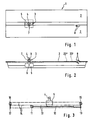
- Fig. 1 eine schematisierte Draufsicht auf die erfindungsgemäße Tragenplattform bzw. -aufnahme,
- Fig. 2 eine schematisierte, teilweise geschnittene Seitenansicht der Tragenplattform bzw. -aufnahme,
- Fig. 3 eine schematisierte Darstellung des motorischen Antriebes des Greifer- bzw. Rückhalteaggregates und
- Fig. 4 eine Seitenansicht des Heckbereiches eines Rettungs- bzw. Krankentransportwagens mit aus der geöffneten Hecktür herausragender, in Beladestellung befindlicher Tragenplattform bzw. -aufnahme.
- 1 is a schematic plan view of the stretcher platform or support according to the invention,
- 2 is a schematic, partially sectioned side view of the stretcher platform or cradle,
- Fig. 3 is a schematic representation of the motor drive of the gripper or restraint unit and
- Fig. 4 is a side view of the rear area of an ambulance or ambulance with a protruding from the open tailgate, in the loading position carrying platform or receptacle.
Die insgesamt mit 1 bezeichnete Tragenplattform bzw. -aufnahme besitzt in Längsrichtung angeordnete platten- oder rinnenförmige Lagerflächen 2 zur Aufnahme einer nur in Fig. 4 dargestellten Trage 20, welche auf den Lagerflächen 2 mittels nicht dargestellter Riegelorgane formschlüssig festgehalten werden kann.The carrier platform or receptacle, designated overall by 1, has plate-shaped or trough-shaped bearing
Die gesamte Tragenplattform bzw. -aufnahme 1 ist innerhalb eines Rettungswagens 21 od.dgl. auf einem nicht dargestellten Tragenlagerungsgestell od.dgl. angeordnet, in der Regel derart, daß eine Höhenverstellung der Tragenplattform bzw. -aufnahme 1 sowie eine wahlweise federbare oder unfederbare Abstützung ermöglicht wird. Darüber hinaus läßt sich die Tragenplattform bzw. -aufnahme 1 in der Regel in Fahrzeuglängsrichtung zwischen einer Transportstellung innerhalb des Fahrzeuges und einer aus Fig. 4 ersichtlichen Beladestellung verschieben, in der die Tragenplattform bzw. -aufnahme 1 durch eine Hecktür des Fahrzeuges hindurch nach außen herausragt. Dabei kann die Tragenplattform bzw. -aufnahme 1 in Beladestellung zusätzlich schräggestellt sein, um das aus dem Fahrzeug herausragende Ende der Tragenplattform bzw. -aufnahme 1 zur Erleichterung des Aufschiebens bzw. des Abnehmens der Trage tieferzulegen.The entire stretcher platform or cradle 1 is inside an
Die Kippbarkeit der Tragenplattform bzw. -aufnahme 1 um eine Querachse kann im übrigen in der Transportstellung auch dazu ausgenutzt werden, eine Kopf-Tief-Lagerung oder eine Kopf-Hoch-Lagerung des Patienten zu ermöglichen.The tiltability of the stretcher platform or receptacle 1 about a transverse axis can also be used in the transport position to enable the patient to be stored head-down or head-up.
Die Tragenplattform bzw. -aufnahme 1 ist üblicherweise für verschiedenartige Tragen geeignet, insbesondere auch für sogenannte Fahrtragen 20, welche ein einklappbares Fahrwerk bzw. mit Rädern versehene einklappbare Beine 22 besitzen (vgl. Fig. 4), wobei das Fahrwerk bzw. die Beine nach Entriegelung beim Auf schieben der Fahrtrage auf die Lagerflächen 2 der Tragenplattform bzw. -aufnahme 1 umklappen, so daß die Fahrtrage 20 insgesamt nur etwa die Höhe einer normalen Trage einnimmt.The stretcher platform or cradle 1 is usually suitable for different types of stretcher, in particular also for so-called
Jedoch wird durch das Zusammenklappen des Fahrwerkes bzw. der Beine ein erhöhter Kraftaufwand notwendig, um die Fahrtrage 20 auf die Lagerflächen 2 der Tragenplattform bzw. -aufnahme 1 zu schieben. Außerdem muß beim Abnehmen der Trage 20 von der Tragenplattform bzw. -aufnahme 1 sorgfältig darauf geachtet werden, daß die Beine 22, welche selbsttätig ausklappen, sobald sie von der Tragenplattform bzw. -aufnahme 1 freikommen, tatsächlich ihre verriegelte Fahrstellung erreichen.However, the folding of the undercarriage or the legs requires an increased effort to push the
Um nun den Sanitätern das Auf schieben der Trage und insbesondere einer Fahrtrage 20 auf die Tragenplattform bzw. -aufnahme 1 zu erleichtern, und um die Trage 20 beim Abnehmen von der Tragenplattform bzw. -aufnahme 1 zu sichern, besitzt die erfindungsgemäße Tragenplattform bzw. -aufnahme 1 ein motorisch angetriebenes Rückhalte- bzw. Greiferaggregat 3, welches in Längsrichtung der Tragenplattform bzw. -aufnahme 1 verschiebbar angeordnet ist und mittels eines an ihm angeordneten Hakens 4 od.dgl. ein Tragenteil zu erfassen und die Trage auf die Tragenplattform bzw. -aufnahme 1 bzw. deren Lagerflächen 2 zu ziehen bzw. an der Tragenplattform bzw. -aufnahme festzuhalten gestattet.In order to make it easier for the paramedics to push the stretcher and in particular a
Der Haken 4 ist an einem Wagen 5 oder einem Schlitten angeordnet, welcher mit Rollen an bzw. in Schienen unterhalb der Lagerflächen 2 in Längsrichtung der Tragenplattform bzw. -aufnahme 1 beweglich geführt ist. Dabei ist der Haken 4 am Wagen 5 um eine Querachse 6 gegen die Kraft einer Federung schwenkbar, welche den Haken 4 in die in Fig. 2 dargestellte aufgerichtete Endlage zu drängen sucht und ein Umklappen des Hakens in derjenigen Richtung zuläßt, in der die Trage beim Beladen der Tragenplattform bzw. -aufnahme 1 auf die Lagerflächen 2 gezogen wird.The
Seitlich am Haken 4 ist eine Führungsrolle 7 angeordnet, welche mit dem benachbarten Rand der einen Lagerfläche 2 bzw. einer gesonderten Führungsleiste zusammenwirkt.A
An dem genannten Rand der einen Lagerfläche 2 bzw. der Führungsleiste sind Aussparungen mit Rampen 8 angeordnet, welche als klappenförmige gefederte Teile ausgebildet sein können und sich aus ihrer dargestellten Schräglage gegen Federkraft in eine Endlage verschwenken lassen, in der die Rampen 8 jeweils in gleicher Ebene wie die Lagerflächen 2 bzw. die die Rampen 8 tragende Führungsleiste liegen.At the mentioned edge of the one
Wird der Wagen 5 mit dem Haken 4 aus der in Fig. 2 dargestellten Stellung nach links verschoben, so läuft die Führungsrolle 7 des Hakens 4 auf der Oberseite des zuge wandten Randes der einen Lagerfläche 2 (bzw. der Führungsleiste).If the
Wird der Wagen 5 nach rechts bewegt, so läuft die Führungsrolle 7 gegen die Unterseite der oberen Rampe 8. Dementsprechend wird der Haken 4 bei weiterer Verschiebung des Wagens 5 nach rechts von der Führungsrolle 7 niedergedrückt, welche sodann auf der Unterseite des zugewandten Randes der einen Lagerfläche 2 (bzw. der Führungsleiste) weiterläuft.If the
Bei nachfolgender Verschiebung des Wagens 5 nach links läuft die Führungsrolle 7 gegen die Oberseite der unteren Rampe 8, so daß sich der Haken 4 unter der ihn beaufschlagenden Federkraft wieder aufrichten kann und die Führungsrolle 7 auf der Oberseite des zugewandten Randes der einen Lagerfläche 2 (bzw. der Führungsleiste) weiterläuft.When the
Dementsprechend kann also der Haken 4 bei Verschiebung des Wagens 5 nach links jeweils nahe der Rampen 8 ein Teil der jeweiligen Trage erfassen und dieselbe auf die Tragenplattform bzw. -aufnahme 1 ziehen.Accordingly, when the
Sobald die Trage von der Tragenplattform bzw. -aufnahme 1 wieder abgenommen werden soll, wird der Wagen 5 nach rechts verschoben, so daß der Haken 4 durch Zusammenwirken seiner Führungsrolle 7 mit der oberen Rampe 8 wiederum eingeklappt wird und ein späteres Abnehmen der Trage von der Tragenplattform bzw. -aufnahme 1 nicht behindern kann.As soon as the stretcher is to be removed from the stretcher platform or receptacle 1 again, the
Die Betätigung des Rückhalte- bzw. Greiferaggregates 3 beim Aufschieben der Trage 20 auf die Tragenplattform bzw. -aufnahme 1 sowie beim Abnehmen der Trage 20 von der Tragen plattform bzw. -aufnahme 1 erfolgt selbsttätig und wird mittels Positionsgeber gesteuert, welche mit Teilen der Trage 20 zusammenwirken:The actuation of the restraint or
Als Positionsgeber sind an der Tragenplattform bzw. -aufnahme 1 mehrere Kontaktplatten 23′ und 23˝ angeordnet, die von tragenseitigen Stützrollen 24 betätigt werden.As a position sensor, a plurality of contact plates 23 'and 23' are arranged on the stretcher platform or receptacle 1, which are actuated by
Wenn die Trage 20 von der Tragenplattform bzw. -aufnahme 1 heruntergenommen und dazu in Fahrzeuglängsrichtung nach rückwärts verschoben werden soll, werden zuerst die Riegelorgane, welche die Trage 20 bei der Fahrt auf der Tragenplattform bzw. -aufnahme 1 unbeweglich arretieren, entriegelt. Damit wird der Haken 4 bzw. dessen Antrieb in Gang gesetzt, und der Haken 4 wird bis in eine Sicherungslage nahe der Rampen 8, verschoben. Wenn nun die Trage 20 in der Zeichnung nach rechts verschoben wird, so drücken die Stützrollen 24 zunächst die Kontaktplatten 23′ nieder. Bei weiterer Verschiebung der Trage 20 nach rechts klappen die Beine 22 in die Fahrstellung, so daß die Trage 20 bei weiterer Verschiebung nach rechts aufgrund der Neigung der Tragenplattform bzw. -aufnahme 1 Bodenberührung erhält und die Stützrollen 24 die Kontaktplatten 23′ entlasten. Diese nach vorangegangener Belastung erfolgende Entlastung der Kontaktplatten 23′ bewirkt, daß der Wagen bzw. Schlitten 5 mit dem Haken 4 über die Rampen 8 hinaus nach rechts verschoben wird, wobei der Haken 4 nach unten klappt und die Trage 20 freigibt.If the
Sollte das Fahrwerk der Trage 20 die Fahrstellung nicht korrekt erreichen, weil z.B. der Bodenabstand der Tragenplattform bzw. -aufnahme 1 zu gering ist und die Beine 22 durch vorzeitige Bodenberührung am Erreichen der verriegelten Fahrstellung gehindert werden, vermögen die Beine 22 die Trage 20 nicht auf dem Boden abzustützen. Damit können die Stützrollen 24 nicht von den Kontaktplatten 23′ abheben, und der Haken 4 bleibt in der Sicherungslage stehen. Auf diese Weise bleibt das Kopfende der Trage 20 mit der Tragenplattform bzw. -aufnahme 1 gekuppelt; auf keinen Fall kann die Trage 20 herabfallen.Should the undercarriage of the
Beim Beladen bzw. beim Auf schieben der Trage 20 auf die Tragenplattform bzw. -aufnahme 1 steht der Haken 4 zunächst rechts von den Rampen 8 in weggeklappter Lage. Sobald die Stützrollen 24 die Kontaktplatten 23′ niederdrücken, stellt sich der Haken 4 automatisch in die Sicherungslage. Nun werden die Beine 22 der Trage 20 entriegelt, ohne daß dabei die Trage 20 von der Tragenplattform bzw. -aufnahme 1 herabfallen könnte.When loading or when pushing the
Nach Entriegelung der Beine 22 läßt sich die Trage 20 weiter nach links schieben, wobei die Stützrollen 24 die Kontaktplatten 23˝ links von den Kontaktplatten 23′ niederdrücken. Dadurch wird der Antrieb des Hakens 4 eingeschaltet, und der Haken 4 bewegt sich in seine linke Endlage, wobei die Trage 20 - mit entriegelten Beinen 22 - auf die Tragenplattform bzw. -aufnahme 1 gezogen wird.After unlocking the
Zur Verschiebung des Wagens 5 ist ein selbsthemmender Antrieb vorgesehen, um zu gewährleisten, daß der Wagen 5 im Falle eines plötzlichen Stillstandes des Antriebes aufgrund einer Störung, beispielsweise einer Unterbrechung der Energiezufuhr, die jeweils erfaßte Trage nicht plötzlich freigeben kann.To move the
Um andererseits die Trage in jedem Falle auch bei stillstehendem Wagen 5 auf die Tragenplattform bzw. -aufnahme 1 auf schieben bzw. von derselben abnehmen zu können, ohne daß der aufrechtstehende Haken 4 stören kann, ist vorgesehen, daß das in aufrechter Stellung des Hakens 4 obere Teil desselben manuell um eine zur Längsachse der Tragenplattform bzw. -aufnahme 1 parallele Achse 9 weggeklappt werden kann. Damit laufen die andernfalls vom Haken 4 erfaßten Tragenteile in jedem Falle über den Haken 4 hinweg. Das Umklappen des freien Endes des Hakens 4 um die Achse 9 kann gegen Federkraft erfolgen, welche das Hakenende jeweils in die Normallage zurückzudrängen sucht. Dabei kann gegebenenfalls vorgesehen sein, daß sich das Ende des Hakens 4 in der seitwärts weggeklappten Stellung verrasten läßt.On the other hand, in order to be able to push the stretcher onto the stretcher platform or receptacle 1 or remove it from the stretcher in any case, even when the
Zum Antrieb des Wagens 5 dient ein Linearantrieb 10.A
Der Linearantrieb 10 kann beispielsweise als elektrisches Spindelaggregat ausgebildet sein, welches unmittelbar den Wagen 5 verschiebt.The
Im vorliegenden Falle ist jedoch vorgesehen, daß das als Linearantrieb 10 vorgesehene elektrische Spindelaggregat eine Rolle 11 relativ zur Tragenplattform bzw. -aufnahme 1 verschiebt. Über diese Rolle 11 läuft ein erstes Seil bzw. eine erste Kette 12, die einerseits am Wagen 5 und andererseits an einem Festpunkt 13 der Tragenplattform bzw. -aufnahme 1 befestigt ist. Eine weitere Kette 14 bzw. ein weiteres Seil od.dgl. läuft vom Wagen 5 aus in zur ersten Kette 12 entgegengesetzter Richtung über eine Rolle 15, die am einen Ende der Tragenplattform bzw. -aufnahme 1 unverschiebbar gelagert ist.In the present case, however, it is provided that the electric spindle unit provided as a
Von dort läuft die Kette 14 zu einer Rolle 16, welche am anderen Ende der Tragenplattform bzw. -aufnahme 1 unverschiebbar angeordnet ist. Von dort läuft die Kette 14 über die verschiebbare Rolle 11 bzw. eine weitere, zusammen mit der Rolle 11 verschiebbare Rolle zu einem weiteren Festpunkt 17. Bei Verschiebung der Rolle 11 in der einen oder anderen Richtung wird dementsprechend der Wagen 5 mit im Vergleich zur Rolle 11 doppelter Verschiebegeschwindigkeit in der einen oder anderen Richtung relativ zur Tragenplattform bzw. -aufnahme 1 verschoben.From there, the chain 14 runs to a
Falls anstelle eines Elektroantriebes ein hydraulischer Antrieb des Wagens 5 erwünscht ist, kann anstelle des elektrischen Spindelaggregates ein hydraulisches Kolben-Zylinder-Aggregat angeordnet werden, ohne die Konstruktion der Tragenplattform bzw. -aufnahme nennenswert zu ändern. Die erwünschte Hemmung des Antriebes für den Fall eines Ausfalles der hydraulischen Druckquelle kann durch Ventile gewährleistet werden, die in einem derartigen Falle die Kolbenarbeitsräume des Kolben-Zylinder-Aggregates abschließen und damit den Kolben und dementsprechend auch den Wagen 5 unbeweglich festhalten.If instead of an electric drive a hydraulic drive of the
Grundsätzlich sind auch pneumatische Aggregate geeignet, wenn im Rettungswagen od.dgl. eine pneumatische Druckquelle zur Verfügung steht.In principle, pneumatic units are also suitable if the like in the ambulance. a pneumatic pressure source is available.
Im übrigen ist es auch möglich und vorteilhaft, für den Antrieb des Rückhalte- bzw. Greiferaggregates 3 einen normalen Elektromotor zu verwenden, der die Kette 14 über ein Ritzel antreibt.In addition, it is also possible and advantageous to use a normal electric motor for driving the retaining or
Hierbei kann das Ritzel anstelle einer der Rollen 15 oder 16 angeordnet sein. Dabei genügt die Anordnung einer Kette 14, die mit dem Rückhalte- bzw. Greiferaggregat 3 verbunden ist und über die Rollen bzw. Ritzel 15 und 16 herumgeführt ist.Here, the pinion can be arranged instead of one of the
Anstelle eines selbsthemmenden Antriebes des Rückhalte- bzw. Greiferaggregates 3 kann auch eine Zwangshemmung oder -verriegelung vorgesehen sein, welche bei Stillstand des Antriebes bzw. bei ausgeschalteter Energieversorung des Antriebes automatisch wirksam wird.Instead of a self-locking drive of the retaining or
Abweichend von der dargestellten Ausführungsform können die Rampen 8 auch in den in Fig. 2 dargestellten Lagen fest angeordnet sein.In a departure from the embodiment shown, the
Außerdem können anstelle der Kontaktplatten 23′ und 23˝ auch andere Positionsgeber, z.B. Näherungsschalter oder Lichtschranken od.dgl., angeordnet sein.In addition, instead of the
Claims (13)
gekennzeichnet
- durch ein an der Tragenplattform bzw. -aufnahme (1) angeordnetes, in deren Längsrichtung durch Federaggregat bzw. Motorantrieb verschiebbares Greiferaggregat (3), welches ein Tragenteil am beladeseitigen Ende der Tragenplattform bzw. -aufnahme zu erfassen und die Trage auf der Tragenplattform bzw. -aufnahme (1) bis in die Soll- bzw. Riegellage zu ziehen gestattet, und/oder
- durch ein Rückhalteaggregat (3), welches beim Abnehmen bzw. Entladen der Trage von der Tragenplattform bzw. -aufnahme (1) das in Beladerichtung vordere Ende (Kopfende) der Trage bzw. ein tragenseitiges Teil in der Nähe dieses Endes der Trage am beladeseitigen Ende der Tragenplattform bzw. -aufnahme (1) bzw. auf dem Weg zum beladeseitigen Ende auslösbar festhält bzw. gegen Herabfallen sichert.1. stretcher platform or holder for stretcher storage racks of ambulances, ambulance or the like, for the lockable mounting of a stretcher that can be placed or pushed onto the stretcher platform or holder,
featured
- By a arranged on the stretcher platform or seat (1), in the longitudinal direction by spring unit or motor drive gripper unit (3), which grasp a carrying part at the loading end of the stretcher platform or seat and the stretcher on the stretcher platform or .-Recording (1) allowed to be pulled into the target or locking position, and / or
- By a restraining unit (3) which, when removing or unloading the stretcher from the stretcher platform or seat (1), the front end (head end) of the stretcher in the loading direction or a part on the stretcher side near this end of the stretcher on the loading side End of the stretcher platform or receptacle (1) or on the way to the loading end releasably holds or secures against falling.
Priority Applications (1)
| Application Number | Priority Date | Filing Date | Title |
|---|---|---|---|
| AT9090116961T ATE104538T1 (en) | 1989-09-08 | 1990-09-04 | PORTER PLATFORM OR. -RECORDING. |
Applications Claiming Priority (2)
| Application Number | Priority Date | Filing Date | Title |
|---|---|---|---|
| DE3929959 | 1989-09-08 | ||
| DE3929959A DE3929959C1 (en) | 1989-09-08 | 1989-09-08 |
Publications (3)
| Publication Number | Publication Date |
|---|---|
| EP0416530A2 true EP0416530A2 (en) | 1991-03-13 |
| EP0416530A3 EP0416530A3 (en) | 1991-11-06 |
| EP0416530B1 EP0416530B1 (en) | 1994-04-20 |
Family
ID=6388963
Family Applications (1)
| Application Number | Title | Priority Date | Filing Date |
|---|---|---|---|
| EP90116961A Expired - Lifetime EP0416530B1 (en) | 1989-09-08 | 1990-09-04 | Platform or receptacle for stretcher |
Country Status (3)
| Country | Link |
|---|---|
| EP (1) | EP0416530B1 (en) |
| AT (1) | ATE104538T1 (en) |
| DE (2) | DE3929959C1 (en) |
Cited By (4)
| Publication number | Priority date | Publication date | Assignee | Title |
|---|---|---|---|---|
| CN109674590A (en) * | 2018-12-17 | 2019-04-26 | 航宇救生装备有限公司 | A kind of stretcher fixed mechanism for aircraft |
| CN110151411A (en) * | 2019-06-05 | 2019-08-23 | 江苏日新医疗设备股份有限公司 | A kind of electrical stretcher storehouse |
| CN114524260A (en) * | 2022-01-30 | 2022-05-24 | 江苏悦达迪科汽车有限公司 | Automatic grabbing and releasing mechanism of electric boarding stretcher |
| CN117162894A (en) * | 2023-09-12 | 2023-12-05 | 徐州海伦哲特种车辆有限公司 | A multifunctional emergency support operation vehicle with rescue function |
Families Citing this family (5)
| Publication number | Priority date | Publication date | Assignee | Title |
|---|---|---|---|---|
| DE102008005900A1 (en) | 2008-01-24 | 2009-07-30 | Bayerisches Rotes Kreuz, Körperschaft des öffentlichen Rechts | Telescopic like extensible ambulance table for use in patient room in emergency vehicle, has actuator driven backwards and forwards in longitudinal direction, and control device controlling drive of actuator depending on position and load |
| ITRE20080040A1 (en) * | 2008-05-08 | 2009-11-09 | Stem Srl | '' STRETCHER AND PATIENT TRANSPORT SYSTEM '' |
| ES2364842B1 (en) * | 2009-01-29 | 2012-08-03 | Productos Metálicos Del Bages, S.L. | CAMILLA HOLDER. |
| DE102011078803B4 (en) | 2011-07-07 | 2017-04-06 | Markus Glaser | System and method for automatically pulling a stretcher into an ambulance |
| DE102014013898A1 (en) * | 2014-09-18 | 2016-03-24 | Rosenbauer International Ag | Rescue basket, as well as equipped Hubrettungsfahrzeug |
Family Cites Families (5)
| Publication number | Priority date | Publication date | Assignee | Title |
|---|---|---|---|---|
| DE8102460U1 (en) * | 1981-07-23 | Binz Gmbh & Co, 7073 Lorch | Stretcher platform frame for receiving a stretcher, in particular in ambulances | |
| DE8006792U1 (en) * | 1980-03-13 | 1980-06-19 | Binz Gmbh & Co, 7073 Lorch | DEVICE FOR LOCKING CARRIERS ON A CARRYING PAD |
| AT384166B (en) * | 1986-01-08 | 1987-10-12 | Zeibig Ernst | FLOATING FRAME FOR ADMINISTERING AN AMBULANCE |
| GB2203999A (en) * | 1987-03-11 | 1988-11-02 | Macclesfield Motor Bodies | Vehicle loading platform |
| DE3736635A1 (en) * | 1987-10-29 | 1989-05-11 | Thomas Strobel | Road vehicle for the horizontal transport of people, in particular ambulance vehicle |
-
1989
- 1989-09-08 DE DE3929959A patent/DE3929959C1/de not_active Expired - Fee Related
-
1990
- 1990-09-04 AT AT9090116961T patent/ATE104538T1/en not_active IP Right Cessation
- 1990-09-04 DE DE59005428T patent/DE59005428D1/en not_active Expired - Fee Related
- 1990-09-04 EP EP90116961A patent/EP0416530B1/en not_active Expired - Lifetime
Cited By (5)
| Publication number | Priority date | Publication date | Assignee | Title |
|---|---|---|---|---|
| CN109674590A (en) * | 2018-12-17 | 2019-04-26 | 航宇救生装备有限公司 | A kind of stretcher fixed mechanism for aircraft |
| CN109674590B (en) * | 2018-12-17 | 2024-04-09 | 航宇救生装备有限公司 | Stretcher fixing mechanism for aircraft |
| CN110151411A (en) * | 2019-06-05 | 2019-08-23 | 江苏日新医疗设备股份有限公司 | A kind of electrical stretcher storehouse |
| CN114524260A (en) * | 2022-01-30 | 2022-05-24 | 江苏悦达迪科汽车有限公司 | Automatic grabbing and releasing mechanism of electric boarding stretcher |
| CN117162894A (en) * | 2023-09-12 | 2023-12-05 | 徐州海伦哲特种车辆有限公司 | A multifunctional emergency support operation vehicle with rescue function |
Also Published As
| Publication number | Publication date |
|---|---|
| DE3929959C1 (en) | 1990-11-08 |
| ATE104538T1 (en) | 1994-05-15 |
| EP0416530A3 (en) | 1991-11-06 |
| DE59005428D1 (en) | 1994-05-26 |
| EP0416530B1 (en) | 1994-04-20 |
Similar Documents
| Publication | Publication Date | Title |
|---|---|---|
| DE69517713T2 (en) | Transfer device for the disabled | |
| DE69304628T2 (en) | Improved boarding device for a rail vehicle | |
| DE2516455C3 (en) | Device for loading and unloading piece goods | |
| EP0379687B1 (en) | Device for putting bedridden patients into other beds | |
| DE69800866T2 (en) | Portable pallet truck with telescopic lifting arm | |
| DE1904938B1 (en) | Transport device for large containers | |
| DE3518202A1 (en) | TRANSPORTABLE MAINTENANCE LIFT | |
| EP3020381B1 (en) | Auxiliary device for a stretcher | |
| EP0524949B1 (en) | Stretcher rack | |
| EP0416530B1 (en) | Platform or receptacle for stretcher | |
| DE1194715B (en) | Device for loading and unloading large, box-like containers on vehicles | |
| DE2325425A1 (en) | TRANSPORT FOR THE PHYSICALLY DISABLED | |
| EP2308442B1 (en) | Hospital and care bed with anti-tip element | |
| DE2758693A1 (en) | Container pick=up and tipping mechanism - has support and tipping frame extending over entire length of vehicle chassis with initial upward movement | |
| WO2011054581A1 (en) | Device for receiving a stretcher | |
| DE68904953T2 (en) | DEVICE FOR AUTOMATIC PARKING OF VEHICLES BY MEANS OF ADJUSTMENT OR. AUTOMATIC COLLECTION OF VEHICLES. | |
| DE3117803C2 (en) | High rack stacker | |
| EP3473580A1 (en) | Loading device | |
| CZ307874B6 (en) | Power-assisted stretchers loader | |
| DE69605284T2 (en) | LOADING VEHICLE | |
| DE4112017A1 (en) | Lifting platform for loading and unloading equipment - is used on fire-fighting vehicles and has combination of horizontal rail and vertical column with stay | |
| EP1870070A2 (en) | Hearse with plate | |
| DE19535918A1 (en) | Bicycle carrier for vehicle roof | |
| DE102015002448B4 (en) | Carrying loading system and ambulance | |
| DE2230328A1 (en) | CONTAINER VEHICLE |
Legal Events
| Date | Code | Title | Description |
|---|---|---|---|
| PUAI | Public reference made under article 153(3) epc to a published international application that has entered the european phase |
Free format text: ORIGINAL CODE: 0009012 |
|
| AK | Designated contracting states |
Kind code of ref document: A2 Designated state(s): AT DE ES FR GB IT NL |
|
| PUAL | Search report despatched |
Free format text: ORIGINAL CODE: 0009013 |
|
| RHK1 | Main classification (correction) |
Ipc: A61G 3/00 |
|
| AK | Designated contracting states |
Kind code of ref document: A3 Designated state(s): AT DE ES FR GB IT NL |
|
| 17P | Request for examination filed |
Effective date: 19920129 |
|
| 17Q | First examination report despatched |
Effective date: 19930629 |
|
| GRAA | (expected) grant |
Free format text: ORIGINAL CODE: 0009210 |
|
| AK | Designated contracting states |
Kind code of ref document: B1 Designated state(s): AT DE ES FR GB IT NL |
|
| PG25 | Lapsed in a contracting state [announced via postgrant information from national office to epo] |
Ref country code: IT Free format text: LAPSE BECAUSE OF FAILURE TO SUBMIT A TRANSLATION OF THE DESCRIPTION OR TO PAY THE FEE WITHIN THE PRE;WARNING: LAPSES OF ITALIAN PATENTS WITH EFFECTIVE DATE BEFORE 2007 MAY HAVE OCCURRED AT ANY TIME BEFORE 2007. THE CORRECT EFFECTIVE DATE MAY BE DIFFERENT FROM THE ONE RECORDED.SCRIBED TIME-LIMIT Effective date: 19940420 Ref country code: ES Free format text: THE PATENT HAS BEEN ANNULLED BY A DECISION OF A NATIONAL AUTHORITY Effective date: 19940420 Ref country code: FR Effective date: 19940420 Ref country code: GB Effective date: 19940420 Ref country code: NL Effective date: 19940420 |
|
| REF | Corresponds to: |
Ref document number: 104538 Country of ref document: AT Date of ref document: 19940515 Kind code of ref document: T |
|
| REF | Corresponds to: |
Ref document number: 59005428 Country of ref document: DE Date of ref document: 19940526 |
|
| PG25 | Lapsed in a contracting state [announced via postgrant information from national office to epo] |
Ref country code: AT Effective date: 19940904 |
|
| EN | Fr: translation not filed | ||
| NLV1 | Nl: lapsed or annulled due to failure to fulfill the requirements of art. 29p and 29m of the patents act | ||
| GBV | Gb: ep patent (uk) treated as always having been void in accordance with gb section 77(7)/1977 [no translation filed] |
Effective date: 19940420 |
|
| PLBE | No opposition filed within time limit |
Free format text: ORIGINAL CODE: 0009261 |
|
| STAA | Information on the status of an ep patent application or granted ep patent |
Free format text: STATUS: NO OPPOSITION FILED WITHIN TIME LIMIT |
|
| 26N | No opposition filed | ||
| PGFP | Annual fee paid to national office [announced via postgrant information from national office to epo] |
Ref country code: DE Payment date: 19981026 Year of fee payment: 9 |
|
| PG25 | Lapsed in a contracting state [announced via postgrant information from national office to epo] |
Ref country code: DE Free format text: LAPSE BECAUSE OF NON-PAYMENT OF DUE FEES Effective date: 20000701 |