EP0416530A2 - Plate-forme respectivement réceptacle pour brancard - Google Patents
Plate-forme respectivement réceptacle pour brancard Download PDFInfo
- Publication number
- EP0416530A2 EP0416530A2 EP90116961A EP90116961A EP0416530A2 EP 0416530 A2 EP0416530 A2 EP 0416530A2 EP 90116961 A EP90116961 A EP 90116961A EP 90116961 A EP90116961 A EP 90116961A EP 0416530 A2 EP0416530 A2 EP 0416530A2
- Authority
- EP
- European Patent Office
- Prior art keywords
- stretcher
- platform
- loading
- carrier
- receptacle
- Prior art date
- Legal status (The legal status is an assumption and is not a legal conclusion. Google has not performed a legal analysis and makes no representation as to the accuracy of the status listed.)
- Granted
Links
Images

Classifications
-
- A—HUMAN NECESSITIES
- A61—MEDICAL OR VETERINARY SCIENCE; HYGIENE
- A61G—TRANSPORT, PERSONAL CONVEYANCES, OR ACCOMMODATION SPECIALLY ADAPTED FOR PATIENTS OR DISABLED PERSONS; OPERATING TABLES OR CHAIRS; CHAIRS FOR DENTISTRY; FUNERAL DEVICES
- A61G3/00—Ambulance aspects of vehicles; Vehicles with special provisions for transporting patients or disabled persons, or their personal conveyances, e.g. for facilitating access of, or for loading, wheelchairs
- A61G3/02—Loading or unloading personal conveyances; Facilitating access of patients or disabled persons to, or exit from, vehicles
- A61G3/0218—Loading or unloading stretchers
- A61G3/0254—Loading or unloading stretchers by moving the stretcher on a horizontal path, e.g. sliding or rolling
-
- A—HUMAN NECESSITIES
- A61—MEDICAL OR VETERINARY SCIENCE; HYGIENE
- A61G—TRANSPORT, PERSONAL CONVEYANCES, OR ACCOMMODATION SPECIALLY ADAPTED FOR PATIENTS OR DISABLED PERSONS; OPERATING TABLES OR CHAIRS; CHAIRS FOR DENTISTRY; FUNERAL DEVICES
- A61G3/00—Ambulance aspects of vehicles; Vehicles with special provisions for transporting patients or disabled persons, or their personal conveyances, e.g. for facilitating access of, or for loading, wheelchairs
- A61G3/02—Loading or unloading personal conveyances; Facilitating access of patients or disabled persons to, or exit from, vehicles
- A61G3/0218—Loading or unloading stretchers
- A61G3/029—Loading or unloading stretchers by powered support
-
- A—HUMAN NECESSITIES
- A61—MEDICAL OR VETERINARY SCIENCE; HYGIENE
- A61G—TRANSPORT, PERSONAL CONVEYANCES, OR ACCOMMODATION SPECIALLY ADAPTED FOR PATIENTS OR DISABLED PERSONS; OPERATING TABLES OR CHAIRS; CHAIRS FOR DENTISTRY; FUNERAL DEVICES
- A61G3/00—Ambulance aspects of vehicles; Vehicles with special provisions for transporting patients or disabled persons, or their personal conveyances, e.g. for facilitating access of, or for loading, wheelchairs
- A61G3/08—Accommodating or securing wheelchairs or stretchers
- A61G3/0816—Accommodating or securing stretchers
- A61G3/0833—Accommodating or securing stretchers using other support
Definitions
- the invention relates to a stretcher platform or carrier for stretcher storage racks or ambulances or the like. for the lockable mounting of a stretcher that can be placed or pushed onto the stretcher platform or holder.
- Carrier platforms or receptacles of this type and associated carrier storage racks are generally known, cf. for example DE-U 81 02 460.
- Ambulance or ambulance vehicles usually have a tailgate through which the stretcher platform or cradle of the stretcher support frame can be accessed so that the stretcher with the injured or sick person to be transported can be placed on or removed from the stretcher support frame with displacement in the vehicle's longitudinal direction.
- the entire stretcher platform or receptacle can be arranged on the stretcher support frame between a transport position inserted into the vehicle and a loading position protruding from the rear door.
- extension parts which can be pulled out or folded out on the stretcher platform or receptacle through the opening of the rear door in order to push the stretcher onto the stretcher platform or receptacle or to remove the stretcher from the stretcher platform or to facilitate recording.
- stretcher carriers which are also referred to as stretcher beds, are advantageous in themselves because the patient transports particularly gently outside the vehicle and especially in the hospital area, i.e. can be driven, the stretcher can also be used as a means of transport to various examination stations in order to avoid an undesirable frequent transfer of the patient.
- stretcher when the stretcher is inserted into the ambulance or ambulance, a significantly increased effort is necessary, although the chassis of such stretcher can be folded in comparatively easily.
- the retractable undercarriage of the stretcher is basically designed so that it automatically folds out into the driving position when the stretcher is pulled down from the stretcher platform or holder.
- the driving position may not be completely reached, for example, because the ground clearance of the stretcher platform or support is too small and the unfolding undercarriage comes into contact with the ground prematurely. If the paramedic does not notice this in time, or if the paramedic slips or stumbles, the stretcher can be released from the stretcher platform or cradle before the chassis can support the stretcher.
- the transported patient falls down from a relatively high height with the stretcher.
- the chassis are stable even in the fully unfolded position, but such stretches are not generally used; In addition, such chassis make it difficult to push the stretcher onto the stretcher platform or cradle.
- a gripper unit which can be displaced in the longitudinal direction by spring unit or motor drive on the stretcher platform or receptacle, which grasp a carrying part at the loading end of the stretcher platform or receptacle and the stretcher on the stretcher platform or - Recording allowed to pull into the target or bolt position, and / or a restraining unit is arranged which, when unloading, the front end (head end) of the stretcher in the loading direction or a part on the stretcher side near this end of the stretcher at the loading end of the stretcher Carrier platform or carrier or on the way to the loading end of the carrier platform or carrier releasably holds or secures against falling.
- the stretcher is sufficient during loading to move the stretcher to the stretcher platform or receptacle in such a way that one end of the stretcher, usually its head end, projects beyond the loading end of the stretcher platform or receptacle to a certain extent and the gripper unit a support part, for example a frame cross member or an axis of the stretcher, can grasp.
- the stretcher can now be pulled onto the stretcher platform or mount with the support of the spring assembly or with motor power, the stretcher's chassis folding away after unlocking.
- the front end of the stretcher in the loading direction remains releasably supported by the restraint unit when unloading at the loading end of the stretcher platform or receptacle, so that the stretcher is only released from the stretcher platform or receptacle correctly after the stretcher has been correctly released and the stretcher falls down from the stretcher Carrier platform or cradle is avoided with sufficient certainty when the undercarriage is not fully extended.
- the gripper unit which also serves as a restraining unit, runs back to an arresting position at the loading end of the stretcher platform or receptacle during unloading or assumes the arresting position. In this way, a single unit can serve both as a loading aid and as a backup during unloading.
- the restraint or gripper unit is designed or arranged in such a way that it secures or allows the front end of the stretcher in the loading direction to be secured against a separation from the stretcher platform or receptacle before the retractable chassis of the stretcher is its leaves the stretcher supporting position. In this way, a particularly high level of safety is ensured even when loading. Because even if the paramedics slip or stumble when pushing the stretcher onto the stretcher platform or cradle, the stretcher can never slide down from the stretcher platform or cradle.
- the stretcher can be released from the restraint or gripper unit with a particularly high degree of safety if the front end of the stretcher in the loading direction is released by that this stretcher is raised relative to the stretcher platform or cradle or - when the stretcher of the stretcher is fully unfolded - rises.
- an actuating device for driving the gripper or restraining unit interacts when loading with such carrying parts which can only be brought into a position activating the actuating device after unlocking the retractable chassis of a stretcher or a carrying bed, or when the actuating device interacts with unloading parts which can only assume a position activating the actuating device after the chassis has been folded out into a ready-to-drive position.
- the gripper or restraint assembly and the stretcher to one another in such a way that the gripper or restraint assembly interacts with a part on the load-bearing side, which is coupled to the locking of the stretcher undercarriage in such a way that the undercarriage is automatically unlocked when the stretcher on the Carrier platform or cradle is pulled or automatically locked when the stretcher is released by the gripper or restraint unit.
- the actuating device of the drive of the gripper or restraint unit can interact with position sensors, for example contact plates, arranged on the stretcher platform or holder, which actuate the actuating device at predetermined positions of the stretcher on the stretcher platform or holder.
- spindle units are arranged to drive the gripper or restraining unit, which ensure self-locking without any further structural modifications.
- These spindle units can be driven by electric motors.
- Such a construction offers the further advantage that the spindle units and their electric motors can optionally be exchanged for fluid, in particular hydraulic piston-cylinder units, even without major structural modification of the stretcher platform or receptacle, the desired inhibition being ensured by corresponding valve units , which block the piston by closing the piston working spaces in the event of failure of the pressure source of the piston-cylinder unit.
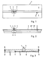
- the carrier platform or receptacle designated overall by 1, has plate-shaped or trough-shaped bearing surfaces 2 arranged in the longitudinal direction for receiving a stretcher 20 which is only shown in FIG. 4 and which can be positively held on the bearing surfaces 2 by means of locking elements (not shown).
- the entire stretcher platform or cradle 1 is inside an ambulance 21 or the like. on a stretcher rack or the like, not shown. arranged, usually in such a way that a height adjustment of the stretcher platform or receptacle 1 and an optionally resilient or unsprung support is made possible.
- the stretcher platform or cradle 1 can generally be moved in the vehicle longitudinal direction between a transport position within the vehicle and a loading position shown in FIG. 4, in which the stretcher platform or cradle 1 protrudes outwards through a rear door of the vehicle .
- the stretcher platform or holder 1 can also be inclined in the loading position in order to lower the end of the stretcher platform or holder 1 protruding from the vehicle in order to facilitate the pushing on or removing of the stretcher.
- the tiltability of the stretcher platform or receptacle 1 about a transverse axis can also be used in the transport position to enable the patient to be stored head-down or head-up.
- the stretcher platform or cradle 1 is usually suitable for different types of stretcher, in particular also for so-called stretcher carriers 20 which have a retractable undercarriage or wheels 22 with retractable legs 22 (see FIG. 4), the undercarriage or the legs following Unlock when pushing on the stretcher on the bearing surfaces 2 of the stretcher platform or holder 1 fold over, so that the stretcher 20 takes up only about the height of a normal stretcher.
- the folding of the undercarriage or the legs requires an increased effort to push the stretcher 20 onto the bearing surfaces 2 of the stretcher platform or holder 1.
- care must be taken to ensure that the legs 22, which automatically fold out as soon as they come free from the stretcher platform or seat 1, actually reach their locked driving position.
- the stretcher platform In order to make it easier for the paramedics to push the stretcher and in particular a stretcher 20 onto the stretcher platform or cradle 1 and to secure the stretcher 20 when it is removed from the stretcher platform or cradle 1, the stretcher platform according to the invention has or Recording 1 a motor-driven restraint or gripper unit 3, which 1 in the longitudinal direction of the stretcher platform or is arranged displaceably and by means of a hook 4 or the like arranged on it. to grasp a supporting part and to pull the stretcher onto the stretcher platform or seat 1 or its storage surfaces 2 or to hold onto the stretcher platform or seat.
- the hook 4 is arranged on a carriage 5 or a carriage, which is movably guided with rollers on or in rails below the bearing surfaces 2 in the longitudinal direction of the carrier platform or holder 1.
- the hook 4 on the carriage 5 can be pivoted about a transverse axis 6 against the force of a suspension which tries to urge the hook 4 into the erected end position shown in FIG. 2 and allows the hook to be folded over in the direction in which the stretcher is carried Loading the stretcher platform or receptacle 1 is pulled onto the storage surfaces 2.
- a guide roller 7 is arranged on the side of the hook 4 and cooperates with the adjacent edge of the one bearing surface 2 or a separate guide bar.
- recesses with ramps 8 are arranged, which can be designed as flap-shaped spring-loaded parts and can be swiveled out of their inclined position against spring force into an end position in which the ramps 8 are each in the same plane how the bearing surfaces 2 and the guide bar carrying the ramps 8 are located.
- the hook 4 can grasp part of the respective stretcher near the ramps 8 and pull the same onto the stretcher platform or holder 1.
- the carriage 5 is shifted to the right, so that the hook 4 is again folded in by the interaction of its guide roller 7 with the upper ramp 8 and a later removal of the stretcher from the Carrier platform or receiving 1 can not hinder.
- a plurality of contact plates 23 'and 23' are arranged on the stretcher platform or receptacle 1, which are actuated by support rollers 24 on the stretcher side.
- the locking elements which immovably lock the stretcher 20 when traveling on the stretcher platform or holder 1 are unlocked.
- the hook 4 or its drive is set in motion, and the hook 4 is shifted into a securing position near the ramps 8. If the stretcher 20 is moved to the right in the drawing, the support rollers 24 first press the contact plates 23 'down.
- the hook 4 When loading or when pushing the stretcher 20 onto the stretcher platform or holder 1, the hook 4 is initially to the right of the ramps 8 in a folded position. As soon as the support rollers 24 press down the contact plates 23 ', the hook 4 automatically moves into the secured position. Now the legs 22 of the stretcher 20 are unlocked without the stretcher 20 falling down from the carrier platform or holder 1.
- the stretcher 20 can be pushed further to the left, the support rollers 24 depressing the contact plates 23 'to the left of the contact plates 23'. As a result, the drive of the hook 4 is switched on and the hook 4 moves into its left end position, the stretcher 20 being pulled onto the carrier platform or holder 1 with the legs 22 unlocked.
- a self-locking drive is provided to ensure that the carriage 5 in the event of a sudden standstill of the drive due to a malfunction, for example an interruption in the energy supply, can not suddenly release the stretcher recorded.
- the hook 4 in the upright position upper part of the same can be manually folded away about an axis 9 parallel to the longitudinal axis of the stretcher platform or support 1. So that the otherwise covered by the hook 4 carrying parts run over the hook 4 in any case.
- the free end of the hook 4 can be folded around the axis 9 against spring force, which tries to push the hook end back into the normal position. If necessary, it can be provided that the end of the hook 4 can be locked in the position folded away sideways.
- a linear drive 10 is used to drive the carriage 5.
- the linear drive 10 can be designed, for example, as an electrical spindle unit which moves the carriage 5 directly.
- the electric spindle unit provided as a linear drive 10 moves a roller 11 relative to the carrier platform or holder 1.
- a first rope or a first chain 12 runs over this roller 11, which is attached on the one hand to the carriage 5 and on the other hand to a fixed point 13 of the stretcher platform or holder 1.
- Another chain 14 or another rope or the like. runs from the carriage 5 in the opposite direction to the first chain 12 via a roller 15 which is immovably mounted at one end of the carrier platform or holder 1.
- the chain 14 runs to a roller 16, which is arranged immovably at the other end of the carrier platform or holder 1. From there, the chain 14 runs over the displaceable roller 11 or a further roller that can be displaced together with the roller 11 to a further fixed point 17.
- the carriage 5 is accordingly also compared to the roller 11 double displacement speed in one direction or the other relative to the carrier platform or holder 1 shifted.
- a hydraulic piston-cylinder unit can be arranged instead of the electric spindle unit without significantly changing the construction of the stretcher platform or holder.
- the desired inhibition of the drive in the event of a failure of the hydraulic pressure source can be ensured by valves which in such a case close off the piston working spaces of the piston-cylinder unit and thus immobilize the piston and accordingly the carriage 5.
- pneumatic units are also suitable if the like in the ambulance. a pneumatic pressure source is available.
- the pinion can be arranged instead of one of the rollers 15 or 16.
- a forced inhibition or locking can also be provided, which takes effect automatically when the drive is at a standstill or when the power supply to the drive is switched off.
- the ramps 8 can also be arranged in a fixed manner in the positions shown in FIG. 2.
- contact plates 23 'and 23 instead of the contact plates 23 'and 23 ⁇ other position sensors, e.g. Proximity switches or light barriers or the like can be arranged.
Landscapes
- Health & Medical Sciences (AREA)
- Public Health (AREA)
- Life Sciences & Earth Sciences (AREA)
- Animal Behavior & Ethology (AREA)
- General Health & Medical Sciences (AREA)
- Veterinary Medicine (AREA)
- Accommodation For Nursing Or Treatment Tables (AREA)
- Ladders (AREA)
- Dental Tools And Instruments Or Auxiliary Dental Instruments (AREA)
- Chair Legs, Seat Parts, And Backrests (AREA)
- Investigating Or Analysing Biological Materials (AREA)
- Materials For Medical Uses (AREA)
- Escalators And Moving Walkways (AREA)
- Invalid Beds And Related Equipment (AREA)
Priority Applications (1)
| Application Number | Priority Date | Filing Date | Title |
|---|---|---|---|
| AT9090116961T ATE104538T1 (de) | 1989-09-08 | 1990-09-04 | Tragenplattform bzw. -aufnahme. |
Applications Claiming Priority (2)
| Application Number | Priority Date | Filing Date | Title |
|---|---|---|---|
| DE3929959 | 1989-09-08 | ||
| DE3929959A DE3929959C1 (fr) | 1989-09-08 | 1989-09-08 |
Publications (3)
| Publication Number | Publication Date |
|---|---|
| EP0416530A2 true EP0416530A2 (fr) | 1991-03-13 |
| EP0416530A3 EP0416530A3 (en) | 1991-11-06 |
| EP0416530B1 EP0416530B1 (fr) | 1994-04-20 |
Family
ID=6388963
Family Applications (1)
| Application Number | Title | Priority Date | Filing Date |
|---|---|---|---|
| EP90116961A Expired - Lifetime EP0416530B1 (fr) | 1989-09-08 | 1990-09-04 | Plate-forme respectivement réceptacle pour brancard |
Country Status (3)
| Country | Link |
|---|---|
| EP (1) | EP0416530B1 (fr) |
| AT (1) | ATE104538T1 (fr) |
| DE (2) | DE3929959C1 (fr) |
Cited By (4)
| Publication number | Priority date | Publication date | Assignee | Title |
|---|---|---|---|---|
| CN109674590A (zh) * | 2018-12-17 | 2019-04-26 | 航宇救生装备有限公司 | 一种用于飞行器的担架固定机构 |
| CN110151411A (zh) * | 2019-06-05 | 2019-08-23 | 江苏日新医疗设备股份有限公司 | 一种电动担架仓 |
| CN114524260A (zh) * | 2022-01-30 | 2022-05-24 | 江苏悦达迪科汽车有限公司 | 一种电动上车担架的自动抓取放出机构 |
| CN117162894A (zh) * | 2023-09-12 | 2023-12-05 | 徐州海伦哲特种车辆有限公司 | 一种具有救护功能的多功能应急保障作业车 |
Families Citing this family (5)
| Publication number | Priority date | Publication date | Assignee | Title |
|---|---|---|---|---|
| DE102008005900A1 (de) | 2008-01-24 | 2009-07-30 | Bayerisches Rotes Kreuz, Körperschaft des öffentlichen Rechts | Ambulanztisch für Rettungsfahrzeuge sowie ein Rettungsfahrzeug aufweisend einen derartigen Ambulanztisch und Verfahren zur Beförderung eines Krankentransportmittels auf einen Ambulanztisch, sowie Verfahren zur Ermittlung des Patientengewichts mittels eines Ambulanztisches |
| ITRE20080040A1 (it) * | 2008-05-08 | 2009-11-09 | Stem Srl | '' barella e sistema per il trasporto di pazienti '' |
| ES2364842B1 (es) * | 2009-01-29 | 2012-08-03 | Productos Metálicos Del Bages, S.L. | Porta-camilla. |
| DE102011078803B4 (de) | 2011-07-07 | 2017-04-06 | Markus Glaser | System und Verfahren zum automatisierten Hinaufziehen einer Fahrtrage in einen Rettungswagen |
| DE102014013898A1 (de) * | 2014-09-18 | 2016-03-24 | Rosenbauer International Ag | Rettungskorb, sowie damit ausgerüstetes Hubrettungsfahrzeug |
Family Cites Families (5)
| Publication number | Priority date | Publication date | Assignee | Title |
|---|---|---|---|---|
| DE8102460U1 (de) * | 1981-07-23 | Binz Gmbh & Co, 7073 Lorch | Tragenbühnengestell zur Aufnahme einer Krankentrage, insbesondere in Krankenfahrzeugen | |
| DE8006792U1 (de) * | 1980-03-13 | 1980-06-19 | Binz Gmbh & Co, 7073 Lorch | Vorrichtung zur arretierung von tragen auf einer tragenauflage |
| AT384166B (de) * | 1986-01-08 | 1987-10-12 | Zeibig Ernst | Schweberahmen zur aufnahme einer krankenbahre |
| GB2203999A (en) * | 1987-03-11 | 1988-11-02 | Macclesfield Motor Bodies | Vehicle loading platform |
| DE3736635A1 (de) * | 1987-10-29 | 1989-05-11 | Thomas Strobel | Strassenfahrzeug zum liegenden transport von personen, insbesondere rettungswagen |
-
1989
- 1989-09-08 DE DE3929959A patent/DE3929959C1/de not_active Expired - Fee Related
-
1990
- 1990-09-04 AT AT9090116961T patent/ATE104538T1/de not_active IP Right Cessation
- 1990-09-04 DE DE59005428T patent/DE59005428D1/de not_active Expired - Fee Related
- 1990-09-04 EP EP90116961A patent/EP0416530B1/fr not_active Expired - Lifetime
Cited By (5)
| Publication number | Priority date | Publication date | Assignee | Title |
|---|---|---|---|---|
| CN109674590A (zh) * | 2018-12-17 | 2019-04-26 | 航宇救生装备有限公司 | 一种用于飞行器的担架固定机构 |
| CN109674590B (zh) * | 2018-12-17 | 2024-04-09 | 航宇救生装备有限公司 | 一种用于飞行器的担架固定机构 |
| CN110151411A (zh) * | 2019-06-05 | 2019-08-23 | 江苏日新医疗设备股份有限公司 | 一种电动担架仓 |
| CN114524260A (zh) * | 2022-01-30 | 2022-05-24 | 江苏悦达迪科汽车有限公司 | 一种电动上车担架的自动抓取放出机构 |
| CN117162894A (zh) * | 2023-09-12 | 2023-12-05 | 徐州海伦哲特种车辆有限公司 | 一种具有救护功能的多功能应急保障作业车 |
Also Published As
| Publication number | Publication date |
|---|---|
| DE3929959C1 (fr) | 1990-11-08 |
| ATE104538T1 (de) | 1994-05-15 |
| EP0416530A3 (en) | 1991-11-06 |
| DE59005428D1 (de) | 1994-05-26 |
| EP0416530B1 (fr) | 1994-04-20 |
Similar Documents
| Publication | Publication Date | Title |
|---|---|---|
| DE69517713T2 (de) | Transfervorrichtung für Behinderte | |
| DE69304628T2 (de) | Verbesserte Einsteigevorrichtung für ein Schienenfahrzeug | |
| DE2516455C3 (de) | Vorrichtung zum Be- und Entladen von Stückgütern | |
| EP0379687B1 (fr) | Dispositif de changement de lit pour patients alités | |
| DE69800866T2 (de) | Transportabler Gabelhubwagen mit teleskopischem Hebearm | |
| DE1904938B1 (de) | Transportvorrichtung fuer Grossbehaelter | |
| DE3518202A1 (de) | Transportabler wartungslift | |
| EP3020381B1 (fr) | Dispositif auxiliaire pour un brancard | |
| EP0524949B1 (fr) | Chassis de civiere | |
| EP0416530B1 (fr) | Plate-forme respectivement réceptacle pour brancard | |
| DE1194715B (de) | Vorrichtung zum Auf- und Abladen grosser, wagenkastenartiger Behaelter auf Fahrzeuge | |
| DE2325425A1 (de) | Transportmittel fuer koerperbehinderte | |
| EP2308442B1 (fr) | Lit pour malades et pour les soins avec élément anti-basculant | |
| DE2758693A1 (de) | Kipp- und wechselvorrichtung fuer lastkraftwagen | |
| WO2011054581A1 (fr) | Dispositif pour recevoir un brancard | |
| DE68904953T2 (de) | Vorrichtung zum automatischen parken von fahrzeugen mit mitteln zum einstellen bzw. automatischen abholen von fahrzeugen. | |
| DE3117803C2 (de) | Hochregalstapler | |
| EP3473580A1 (fr) | Dispositif d'embarquement | |
| CZ307874B6 (cs) | Nakládací zařízení pro nosítka s posilovačem | |
| DE69605284T2 (de) | Lastaufnahme-fahrzeug | |
| DE4112017A1 (de) | Einrichtung an feuerwehrfahrzeugen oder dgl. zum be- oder entladen von geraeten | |
| EP1870070A2 (fr) | Corbillard doté d'une assiette | |
| DE19535918A1 (de) | Autodach-Fahrradträger | |
| DE102015002448B4 (de) | Tragenverladesystem und Krankentransportwagen | |
| DE2230328A1 (de) | Behaelter-fahrzeug |
Legal Events
| Date | Code | Title | Description |
|---|---|---|---|
| PUAI | Public reference made under article 153(3) epc to a published international application that has entered the european phase |
Free format text: ORIGINAL CODE: 0009012 |
|
| AK | Designated contracting states |
Kind code of ref document: A2 Designated state(s): AT DE ES FR GB IT NL |
|
| PUAL | Search report despatched |
Free format text: ORIGINAL CODE: 0009013 |
|
| RHK1 | Main classification (correction) |
Ipc: A61G 3/00 |
|
| AK | Designated contracting states |
Kind code of ref document: A3 Designated state(s): AT DE ES FR GB IT NL |
|
| 17P | Request for examination filed |
Effective date: 19920129 |
|
| 17Q | First examination report despatched |
Effective date: 19930629 |
|
| GRAA | (expected) grant |
Free format text: ORIGINAL CODE: 0009210 |
|
| AK | Designated contracting states |
Kind code of ref document: B1 Designated state(s): AT DE ES FR GB IT NL |
|
| PG25 | Lapsed in a contracting state [announced via postgrant information from national office to epo] |
Ref country code: IT Free format text: LAPSE BECAUSE OF FAILURE TO SUBMIT A TRANSLATION OF THE DESCRIPTION OR TO PAY THE FEE WITHIN THE PRE;WARNING: LAPSES OF ITALIAN PATENTS WITH EFFECTIVE DATE BEFORE 2007 MAY HAVE OCCURRED AT ANY TIME BEFORE 2007. THE CORRECT EFFECTIVE DATE MAY BE DIFFERENT FROM THE ONE RECORDED.SCRIBED TIME-LIMIT Effective date: 19940420 Ref country code: ES Free format text: THE PATENT HAS BEEN ANNULLED BY A DECISION OF A NATIONAL AUTHORITY Effective date: 19940420 Ref country code: FR Effective date: 19940420 Ref country code: GB Effective date: 19940420 Ref country code: NL Effective date: 19940420 |
|
| REF | Corresponds to: |
Ref document number: 104538 Country of ref document: AT Date of ref document: 19940515 Kind code of ref document: T |
|
| REF | Corresponds to: |
Ref document number: 59005428 Country of ref document: DE Date of ref document: 19940526 |
|
| PG25 | Lapsed in a contracting state [announced via postgrant information from national office to epo] |
Ref country code: AT Effective date: 19940904 |
|
| EN | Fr: translation not filed | ||
| NLV1 | Nl: lapsed or annulled due to failure to fulfill the requirements of art. 29p and 29m of the patents act | ||
| GBV | Gb: ep patent (uk) treated as always having been void in accordance with gb section 77(7)/1977 [no translation filed] |
Effective date: 19940420 |
|
| PLBE | No opposition filed within time limit |
Free format text: ORIGINAL CODE: 0009261 |
|
| STAA | Information on the status of an ep patent application or granted ep patent |
Free format text: STATUS: NO OPPOSITION FILED WITHIN TIME LIMIT |
|
| 26N | No opposition filed | ||
| PGFP | Annual fee paid to national office [announced via postgrant information from national office to epo] |
Ref country code: DE Payment date: 19981026 Year of fee payment: 9 |
|
| PG25 | Lapsed in a contracting state [announced via postgrant information from national office to epo] |
Ref country code: DE Free format text: LAPSE BECAUSE OF NON-PAYMENT OF DUE FEES Effective date: 20000701 |