EP0416537B1 - Coupleur à fibre optique - Google Patents
Coupleur à fibre optique Download PDFInfo
- Publication number
- EP0416537B1 EP0416537B1 EP90116975A EP90116975A EP0416537B1 EP 0416537 B1 EP0416537 B1 EP 0416537B1 EP 90116975 A EP90116975 A EP 90116975A EP 90116975 A EP90116975 A EP 90116975A EP 0416537 B1 EP0416537 B1 EP 0416537B1
- Authority
- EP
- European Patent Office
- Prior art keywords
- optical fiber
- cladding
- optical
- coupler
- core
- Prior art date
- Legal status (The legal status is an assumption and is not a legal conclusion. Google has not performed a legal analysis and makes no representation as to the accuracy of the status listed.)
- Expired - Lifetime
Links
- 239000013307 optical fiber Substances 0.000 title claims description 98
- 238000005253 cladding Methods 0.000 claims description 24
- 230000008878 coupling Effects 0.000 claims description 7
- 238000010168 coupling process Methods 0.000 claims description 7
- 238000005859 coupling reaction Methods 0.000 claims description 7
- 230000003287 optical effect Effects 0.000 claims description 6
- 230000001902 propagating effect Effects 0.000 claims description 6
- 238000004519 manufacturing process Methods 0.000 claims description 5
- 230000000644 propagated effect Effects 0.000 claims description 5
- 239000000835 fiber Substances 0.000 claims description 4
- 238000012544 monitoring process Methods 0.000 claims description 3
- 239000000470 constituent Substances 0.000 claims 5
- 235000012239 silicon dioxide Nutrition 0.000 description 5
- VYPSYNLAJGMNEJ-UHFFFAOYSA-N Silicium dioxide Chemical group O=[Si]=O VYPSYNLAJGMNEJ-UHFFFAOYSA-N 0.000 description 3
- 239000000853 adhesive Substances 0.000 description 3
- 238000009826 distribution Methods 0.000 description 3
- 238000000576 coating method Methods 0.000 description 2
- 238000003780 insertion Methods 0.000 description 2
- 230000037431 insertion Effects 0.000 description 2
- 238000005259 measurement Methods 0.000 description 2
- 238000000034 method Methods 0.000 description 2
- 239000010453 quartz Substances 0.000 description 2
- KRHYYFGTRYWZRS-UHFFFAOYSA-N Fluorane Chemical compound F KRHYYFGTRYWZRS-UHFFFAOYSA-N 0.000 description 1
- 239000011248 coating agent Substances 0.000 description 1
- 238000004891 communication Methods 0.000 description 1
- 238000013461 design Methods 0.000 description 1
- 238000010586 diagram Methods 0.000 description 1
- 230000004927 fusion Effects 0.000 description 1
- 239000003365 glass fiber Substances 0.000 description 1
- 229960002050 hydrofluoric acid Drugs 0.000 description 1
- 229910052739 hydrogen Inorganic materials 0.000 description 1
- 239000001257 hydrogen Substances 0.000 description 1
- 238000012986 modification Methods 0.000 description 1
- 230000004048 modification Effects 0.000 description 1
- 239000004065 semiconductor Substances 0.000 description 1
- 238000003892 spreading Methods 0.000 description 1
Images

Classifications
-
- G—PHYSICS
- G02—OPTICS
- G02B—OPTICAL ELEMENTS, SYSTEMS OR APPARATUS
- G02B6/00—Light guides; Structural details of arrangements comprising light guides and other optical elements, e.g. couplings
- G02B6/24—Coupling light guides
- G02B6/26—Optical coupling means
- G02B6/28—Optical coupling means having data bus means, i.e. plural waveguides interconnected and providing an inherently bidirectional system by mixing and splitting signals
- G02B6/293—Optical coupling means having data bus means, i.e. plural waveguides interconnected and providing an inherently bidirectional system by mixing and splitting signals with wavelength selective means
- G02B6/29331—Optical coupling means having data bus means, i.e. plural waveguides interconnected and providing an inherently bidirectional system by mixing and splitting signals with wavelength selective means operating by evanescent wave coupling
- G02B6/29332—Wavelength selective couplers, i.e. based on evanescent coupling between light guides, e.g. fused fibre couplers with transverse coupling between fibres having different propagation constant wavelength dependency
Definitions
- the present invention relates to an optical fiber coupler, and more particularly to a single-mode optical fiber coupler in which biconical optical fibers are coupled with each other.
- optical fiber coupler In a conventional optical fiber coupler, longitudinal coatings of the same kind of optical fibers are partly removed and exposed glass fiber portions of the optical fibers are fused with each other and elongated at the fused portion in order to accomplish optical branching and coupling.
- multi-mode optical fibers are used.
- Another conventional optical fiber coupler of the single mode type is described in prior art EP-A-0 293 289.
- the optical fiber coupler which is wavelength independent comprises two single mode fibers positioned side by side which are fused in a manner such that they taper down into a substantially circular cross section coupling region wherein the two cores of the fibers run therethrough.
- coupling of light is achieved across a relatively broad range of wavelengths.
- optical coupler for combining and branching light at a specified wavelength is being studied.
- optical fibers to be used are of different core diameters and have a difference in refractive indices between the core and the cladding of each optical fiber so as to combine and branch light of 1.53 ⁇ m and 0.83 ⁇ m.
- single-mode optical fibers having wavelengths which are comparatively far from each other, are used to thereby produce coupling of light in a cladding mode at a long wavelength by utilizing the fact that the optical fibers greatly differ from each other in distribution of light propagated. It is therefore impossible to perform combining and branching of light with wavelength selectivity at wavelengths close to each other.
- the present invention presents an optical fiber coupler comprising the features set out in claim 1.
- the present invention also provides a method for the manufacture of such an optical fiber coupler comprising the steps set out in claim 6.
- a plurality of single-mode optical fibers having respective claddings which are different in refractive index are fused with each other and then elongated at the fused portion.
- a branching characteristic like a band pass filter is shown at a wavelength at which the respective light propagation constants of the different optical fibers agree with each other and the optical fiber coupler exhibits wavelength selectivity.
- a light distribution/combination state results from an evanescent field spreading out of the core of an optical fiber so that the cladding thereof functions as a core, and the air which is an ambient medium functions as a cladding.
- the branching and combining of light are both performed in the tapered portion.
- the characteristics of the coupler depend on the condition of fusion between the two optical fibers and the cladding structure such as the shape of the tapered portion, refractive indices of the claddings and cores, and cladding diameter.
- the propagation constants ⁇ of the two optical fibers are equal to each other and, therefore, if the coupling length in the tapered portion is selected properly, it is possible to branch all light power propagating in one of the optical fibers into the other optical fiber at a desired wavelength.
- the constants ⁇ thereof are different from each other, so that the light power which can be branched is limited in proportion to the difference between the constants ⁇ .
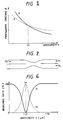
- FIGURE 1 shows that respective wavelength characteristics of propagation constants ⁇ of an optical fiber A having a large difference in refractive index between the cladding and core thereof and having small core diameter, and another optical fiber B having a small difference in refractive index between the cladding and core thereof and having a large core diameter. That is, the optical fiber A has a steeper inclination in its characteristic curve and a larger wave-length dependency in its propagation constant. On the other hand, the optical fiber B has a gentle inclination. There should be an accordant point between both the curves. Assuming the wavelength of the accordant point is ⁇ P , the difference in propagation constant ⁇ between the optical fibers becomes large as the wavelength becomes far from the wavelength ⁇ P .
- the input light power P0 is propagated from an input terminal of optical fiber 1 and the output light power P1 is propagated to an output terminal thereof.
- the branch light power P2 is branched to the branch optical fiber 2 and propagated to an output terminal thereof.
- the wavelength dependency of the branching ratio is shown in Fig. 6.
- the output shows a characteristic like a band pass filter at the wavelength of 1.31 ⁇ m.
- optical fiber coupler A specific example of the optical fiber coupler on the basis of the above discussion will be described below.
- optical fiber having a portion of pure silica acting as a cladding and another portion Ge-doped so as to increase its refractive index difference by 0.3% to thereby act as a core was used as the optical fiber 1.
- Another optical fiber having a portion of pure silica acting as a core and another portion F-doped so as to decrease its refractive index difference by 0.3% to thereby act as a cladding was used as the branch optical fiber 2.
- the parameters of each of the optical fibers were such that the mode thereof was a single-mode, the mode field diameter was about 10 ⁇ m, the cut-off wavelength was 1.2 ⁇ m, and the outer diameter of the cladding was 125 ⁇ m.
- the coating of the optical fiber 1 having the Ge-doped core was partly removed and etched with a fluoric acid so that the outer diameter of the cladding thereof became about 49 ⁇ m, and the optical fiber 1 was combined with the branch optical fiber 2 having the pure silica core and an outer diameter of 125 ⁇ m.
- the two optical fibers were fused with each other and then elongated at the fused portion using heat generated by an oxy-hydrogen burner.
- a semiconductor laser with a oscillating wavelength of 1.31 ⁇ m was connected to one end of the optical fiber 1 as an input source thereof, and a power meter was connected to the remote end of branch optical fiber 2. The elongation was performed while simultaneously monitoring the branch light power P2 output of the branch optical fiber 2.
- the elongation was continued until the branch light power P2 at the power meter reached a maximum value.
- the fused and elongated portion was fixed to a quartz case with an adhesive agent and then taken out, thereby making up a coupler.
- the adhesive agent was applied to the opposite ends of the fused and elongated portion so as not to allow the adhesive agent to make contact with the tapered portion 3.
- FIGURE 3 shows a schematic view of an optical fiber coupler according to the present invention.
- the length of the tapered portion 3 is about 30 mm, and the minimum diameter of the fused portion is about 20 ⁇ m.
- FIGURE 5 shows the result of measurement of the wavelength dependency of the insertion loss of this optical fiber coupler.
- a monochrometer was connected to one end of the optical fiber 1 having the Ge-doped core, and a power meter was connected to the side of the other end of the optical fiber 1 and branch optical fiber 2. While changing the wavelength of incident light, by varying the monochrometer, the output of the power meter was measured so as to measure the wavelength dependency.
- the optical fiber 1 at the input terminal was cut off and a power meter is connected to the cut-off portion of the optical fiber 1, and the incident power P0 was measured while changing the wavelength of the incident light in the same manner. Then, the differences (P1-P0) and (P2-P0) were calculated.
- an optical fiber coupler showing the same characteristics as that in the above discussion was obtained.
Landscapes
- Physics & Mathematics (AREA)
- General Physics & Mathematics (AREA)
- Optics & Photonics (AREA)
- Mechanical Coupling Of Light Guides (AREA)
- Optical Couplings Of Light Guides (AREA)
- Optical Filters (AREA)
- Optical Integrated Circuits (AREA)
Claims (7)
- Coupleur à fibres optiques comprenant :
au moins des première (1) et seconde (2) fibres optiques monomodes constitutives pour propager la lumière, chaque fibre optique comportant une âme et un gainage, lesdits gainages présentant des indices de réfraction différents ;
lesdites fibres optiques constitutives comportant une partie fondue (3) au niveau de laquelle lesdites fibres optiques ont été fondues latéralement ensemble et allongées ;
le gainage de ladite première fibre optique (1) présentant un indice de réfraction comparativement élevé par rapport à celui du gainage de ladite seconde fibre optique (2),
caractérisé en ce que le diamètre externe de ladite première fibre optique constitutive est inférieur à celui de ladite seconde fibre optique et ainsi, la partie fondue résultante (3) combine et branche la lumière propagée seulement pour une unique longueur d'onde spécifiée, ledit coupleur à fibres optiques fonctionnant de ce fait en tant que filtre passe-bande. - Coupleur à fibres optiques selon la revendication 1, ladite première fibre optique présentant un diamètre d'âme inférieur à celui de ladite seconde fibre optique.
- Coupleur à fibres optiques selon la revendication 1, dans lequel l'âme de ladite première fibre optique est dopée au Ge de manière à augmenter son indice de réfraction et le gainage de ladite seconde fibre optique est dopé au F de manière à diminuer son indice de réfraction.
- Coupleur à fibres optiques selon la revendication 1, dans lequel ladite partie fondue est d'une longueur prédéterminée de telle sorte que le coupleur optique présente une caractéristique de performance prédéterminée pour ladite unique longueur d'onde spécifiée.
- Coupleur à fibres optiques selon la revendication 1, dans lequel la longueur de couplage de la partie à flancs inclinés est telle que la totalité de la puissance lumineuse d'entrée se propageant selon ladite unique longueur d'onde spécifiée est couplée depuis l'une desdites première et seconde fibres optiques dans l'autre fibre optique.
- Procédé de fabrication d'un coupleur à fibres optiques, comprenant les étapes de :
sélection de première et seconde fibres optiques constitutives, lesdites fibres optiques comportant chacune une âme et un gainage ;
fusion ensemble de parties latérales respectives desdites première et seconde fibres optiques ;
allongement de ladite partie fondue ;
surveillance des caractéristiques dudit coupleur optique pendant l'allongement de manière à obtenir une performance souhaitée,
caractérisé en ce qu'il comprend en outre les étapes de :
dopage initial au Ge de l'âme de ladite première fibre optique constitutive de manière à augmenter l'indice de réfraction de ladite âme de ladite première fibre optique ;
dopage initial au F du gainage de ladite première fibre optique de manière à diminuer l'indice de réfraction dudit gainage de ladite seconde fibre optique ; et
enlèvement d'une partie dudit gainage de ladite première fibre optique de manière à réduire le diamètre externe de ladite première fibre optique avant la mise en oeuvre de ladite étape de fusion ; et mise en oeuvre de ladite étape de surveillance pour seulement une unique longueur d'onde spécifiée, pour permettre ainsi la production d'un coupleur à fibres optiques qui fonctionne en tant que filtre passe-bande pour ladite unique longueur d'onde spécifiée. - Procédé de fabrication d'un coupleur à fibres optiques selon la revendication 6, comprenant en outre l'étape de :
arrêt de l'allongement de la partie fondue lorsque la lumière se propage au travers de ladite partie fondue à une unique longueur d'onde spécifiée maximum.
Applications Claiming Priority (2)
| Application Number | Priority Date | Filing Date | Title |
|---|---|---|---|
| JP231046/89 | 1989-09-06 | ||
| JP1231046A JPH0799407B2 (ja) | 1989-09-06 | 1989-09-06 | 光ファイバカプラ |
Publications (3)
| Publication Number | Publication Date |
|---|---|
| EP0416537A2 EP0416537A2 (fr) | 1991-03-13 |
| EP0416537A3 EP0416537A3 (en) | 1991-07-24 |
| EP0416537B1 true EP0416537B1 (fr) | 1994-11-30 |
Family
ID=16917436
Family Applications (1)
| Application Number | Title | Priority Date | Filing Date |
|---|---|---|---|
| EP90116975A Expired - Lifetime EP0416537B1 (fr) | 1989-09-06 | 1990-09-04 | Coupleur à fibre optique |
Country Status (6)
| Country | Link |
|---|---|
| US (1) | US5129020A (fr) |
| EP (1) | EP0416537B1 (fr) |
| JP (1) | JPH0799407B2 (fr) |
| AU (1) | AU631006B2 (fr) |
| CA (1) | CA2024225C (fr) |
| DE (1) | DE69014493T2 (fr) |
Families Citing this family (13)
| Publication number | Priority date | Publication date | Assignee | Title |
|---|---|---|---|---|
| US5179603A (en) * | 1991-03-18 | 1993-01-12 | Corning Incorporated | Optical fiber amplifier and coupler |
| JPH04322207A (ja) * | 1991-04-23 | 1992-11-12 | Japan Aviation Electron Ind Ltd | 光ファイバカプラ |
| CA2071344C (fr) * | 1991-06-18 | 1997-04-15 | Hiroshi Suganuma | Procede pour l'obtention d'un connecteur de fibres optiques |
| JPH07128540A (ja) * | 1992-06-01 | 1995-05-19 | Polaroid Corp | 波長選択エネルギ伝送装置 |
| JP2957055B2 (ja) * | 1992-12-08 | 1999-10-04 | 株式会社精工技研 | 光分岐結合器 |
| US5295211A (en) * | 1993-01-07 | 1994-03-15 | Corning Incorporated | Fiber amplifier coupler |
| JPH06250042A (ja) * | 1993-03-01 | 1994-09-09 | Shin Etsu Chem Co Ltd | 広波長域光ファイバ型カプラおよびその製造方法 |
| AU721745B2 (en) | 1996-12-31 | 2000-07-13 | Corning Incorporated | Optical couplers with multilayer fibers |
| CA2289962C (fr) * | 1999-11-17 | 2006-01-17 | Itf Optical Technologies Inc.-Technologies Optiques Itf Inc. | Fabrication de photocoupleurs de fibres monomodes de multiplexage et de demultiplexage |
| EP1217400A1 (fr) * | 2000-12-22 | 2002-06-26 | Corning O.T.I. S.p.A. | Procédé pour fabriquer des épissures entre deux fibres optiques différentes l'une de l'autre |
| JP2007072433A (ja) * | 2005-08-11 | 2007-03-22 | Ricoh Co Ltd | 光集積素子及び光制御素子 |
| WO2007107163A1 (fr) * | 2006-03-17 | 2007-09-27 | Crystal Fibre A/S | Coupleur optique, son procede de fabrication et son utilisation |
| CN105785510A (zh) * | 2014-12-23 | 2016-07-20 | 北京邮电大学 | 基于拉锥方法的光纤耦合器及其制作方法 |
Family Cites Families (13)
| Publication number | Priority date | Publication date | Assignee | Title |
|---|---|---|---|---|
| BE525632A (fr) * | 1953-01-14 | |||
| GB2038017B (en) * | 1978-12-20 | 1982-11-24 | Standard Telephones Cables Ltd | Optical fibre directional coupler |
| DE2942318A1 (de) * | 1979-10-19 | 1981-04-30 | Licentia Patent-Verwaltungs-Gmbh, 6000 Frankfurt | Optisches verzweigungsglied und verfahren zur herstellung eines optischen verzweigungsglieds |
| US4490163A (en) * | 1982-03-22 | 1984-12-25 | U.S. Philips Corporation | Method of manufacturing a fiber-optical coupling element |
| JPS6057303A (ja) * | 1983-09-08 | 1985-04-03 | Nippon Telegr & Teleph Corp <Ntt> | フアイバ形結合子 |
| EP0209998A2 (fr) * | 1985-07-17 | 1987-01-28 | Andrew Corporation | Méthode de fabrication de connecteurs à fibres optiques et méthode d'accordage utilisant la diffusion |
| GB8519183D0 (en) * | 1985-07-30 | 1985-09-04 | British Telecomm | Optical fused couplers |
| JPS6350805A (ja) * | 1986-08-21 | 1988-03-03 | Nippon Telegr & Teleph Corp <Ntt> | 光結合器 |
| JPS63216008A (ja) * | 1987-03-05 | 1988-09-08 | Furukawa Electric Co Ltd:The | 広波長域シングルモ−ド溶融カプラ |
| US4822126A (en) * | 1987-05-21 | 1989-04-18 | Amphenol Corporation | Wavelength independent coupler and method of manufacture thereof |
| GB2209846B (en) * | 1987-09-17 | 1992-03-04 | Pirelli General Plc | Optical fibre wavelength filter having two cores |
| US4976512A (en) * | 1989-04-05 | 1990-12-11 | Safaai Jazi Ahmad | Narrowband fiberoptic spectral filter formed from fibers having a refractive index with a W profile and a step profile |
| US5011251A (en) * | 1989-12-08 | 1991-04-30 | Corning Incorporated | Achromatic fiber optic coupler |
-
1989
- 1989-09-06 JP JP1231046A patent/JPH0799407B2/ja not_active Expired - Fee Related
-
1990
- 1990-08-29 CA CA002024225A patent/CA2024225C/fr not_active Expired - Fee Related
- 1990-09-04 EP EP90116975A patent/EP0416537B1/fr not_active Expired - Lifetime
- 1990-09-04 DE DE69014493T patent/DE69014493T2/de not_active Expired - Fee Related
- 1990-09-04 AU AU62162/90A patent/AU631006B2/en not_active Ceased
- 1990-09-06 US US07/578,292 patent/US5129020A/en not_active Expired - Fee Related
Also Published As
| Publication number | Publication date |
|---|---|
| US5129020A (en) | 1992-07-07 |
| AU6216290A (en) | 1991-03-14 |
| JPH0394208A (ja) | 1991-04-19 |
| DE69014493D1 (de) | 1995-01-12 |
| CA2024225C (fr) | 1998-04-14 |
| JPH0799407B2 (ja) | 1995-10-25 |
| AU631006B2 (en) | 1992-11-12 |
| EP0416537A2 (fr) | 1991-03-13 |
| CA2024225A1 (fr) | 1991-03-07 |
| DE69014493T2 (de) | 1995-04-20 |
| EP0416537A3 (en) | 1991-07-24 |
Similar Documents
| Publication | Publication Date | Title |
|---|---|---|
| US4772085A (en) | Multimode fiber optic coupler and method for making | |
| EP0606583B1 (fr) | Coupleur achromatique pour fibres optiques | |
| US4877300A (en) | Non-adiabatically-tapered connector | |
| US4763977A (en) | Optical fiber coupler with tunable coupling ratio and method of making | |
| CA1294805C (fr) | Coupleurs de fibres optiques | |
| EP0783117B1 (fr) | Fibres optiques pour atténuation optique | |
| EP0607570B1 (fr) | Coupleur et amplificateur à fibres optiques | |
| US5129020A (en) | Wavelength selective optical fiber coupler | |
| JPH03186809A (ja) | アクロマチックファイバオプティックカプラおよびその製造方法 | |
| EP0293289A2 (fr) | Coupleur indépendant de la longueur d'onde et son procédé de fabrication | |
| JPH08262244A (ja) | 集積光学導波管用サイド・ギャップ・モード・テーパリング | |
| KR100358418B1 (ko) | 용융형 모드분할 방향성 결합기의 제조방법 | |
| CA2309564C (fr) | Methode de fabrication d'un coupleur a fibres optiques servant au maintien de la polarisation | |
| EP0610973B1 (fr) | Coupleur à fibre optique | |
| KR19980036474A (ko) | 모드 진화 광커플러 및 그 제조방법 | |
| US5035477A (en) | Method of changing the spot diameter of single-mode step-index fibers, and single-mode fiber coupling unit made by said method | |
| JP3784593B2 (ja) | シングル・マルチモード光ファイバカプラ及びその製造方法 | |
| US4775209A (en) | Fiber-optic coupler comprising intertwined monomode fibers of different diameter | |
| EP0295039A2 (fr) | Coupleur pour guide d'onde optique | |
| JP2635720B2 (ja) | 光ファイバカプラ | |
| JP3101958B2 (ja) | 広帯域カップラおよびその製造方法 | |
| JP2980248B2 (ja) | 光ファイバカップラ | |
| JPH08220369A (ja) | 光ファイバカプラおよびその製造方法 | |
| JP2000356723A (ja) | 伝搬モード変換素子およびその製造方法 | |
| JP2848832B2 (ja) | 広帯域形光ファイバカプラ |
Legal Events
| Date | Code | Title | Description |
|---|---|---|---|
| PUAI | Public reference made under article 153(3) epc to a published international application that has entered the european phase |
Free format text: ORIGINAL CODE: 0009012 |
|
| 17P | Request for examination filed |
Effective date: 19901220 |
|
| AK | Designated contracting states |
Kind code of ref document: A2 Designated state(s): DE FR GB IT NL |
|
| PUAL | Search report despatched |
Free format text: ORIGINAL CODE: 0009013 |
|
| AK | Designated contracting states |
Kind code of ref document: A3 Designated state(s): DE FR GB IT NL |
|
| 17Q | First examination report despatched |
Effective date: 19920903 |
|
| GRAA | (expected) grant |
Free format text: ORIGINAL CODE: 0009210 |
|
| AK | Designated contracting states |
Kind code of ref document: B1 Designated state(s): DE FR GB IT NL |
|
| REF | Corresponds to: |
Ref document number: 69014493 Country of ref document: DE Date of ref document: 19950112 |
|
| ITF | It: translation for a ep patent filed | ||
| ET | Fr: translation filed | ||
| PLBE | No opposition filed within time limit |
Free format text: ORIGINAL CODE: 0009261 |
|
| STAA | Information on the status of an ep patent application or granted ep patent |
Free format text: STATUS: NO OPPOSITION FILED WITHIN TIME LIMIT |
|
| 26N | No opposition filed | ||
| REG | Reference to a national code |
Ref country code: GB Ref legal event code: 746 Effective date: 19990614 |
|
| REG | Reference to a national code |
Ref country code: GB Ref legal event code: IF02 |
|
| PGFP | Annual fee paid to national office [announced via postgrant information from national office to epo] |
Ref country code: GB Payment date: 20020904 Year of fee payment: 13 |
|
| PGFP | Annual fee paid to national office [announced via postgrant information from national office to epo] |
Ref country code: FR Payment date: 20020910 Year of fee payment: 13 |
|
| PGFP | Annual fee paid to national office [announced via postgrant information from national office to epo] |
Ref country code: DE Payment date: 20020911 Year of fee payment: 13 |
|
| PGFP | Annual fee paid to national office [announced via postgrant information from national office to epo] |
Ref country code: NL Payment date: 20020930 Year of fee payment: 13 |
|
| PG25 | Lapsed in a contracting state [announced via postgrant information from national office to epo] |
Ref country code: GB Free format text: LAPSE BECAUSE OF NON-PAYMENT OF DUE FEES Effective date: 20030904 |
|
| PG25 | Lapsed in a contracting state [announced via postgrant information from national office to epo] |
Ref country code: NL Free format text: LAPSE BECAUSE OF NON-PAYMENT OF DUE FEES Effective date: 20040401 Ref country code: DE Free format text: LAPSE BECAUSE OF NON-PAYMENT OF DUE FEES Effective date: 20040401 |
|
| GBPC | Gb: european patent ceased through non-payment of renewal fee | ||
| PG25 | Lapsed in a contracting state [announced via postgrant information from national office to epo] |
Ref country code: FR Free format text: LAPSE BECAUSE OF NON-PAYMENT OF DUE FEES Effective date: 20040528 |
|
| NLV4 | Nl: lapsed or anulled due to non-payment of the annual fee |
Effective date: 20040401 |
|
| REG | Reference to a national code |
Ref country code: FR Ref legal event code: ST |
|
| PG25 | Lapsed in a contracting state [announced via postgrant information from national office to epo] |
Ref country code: IT Free format text: LAPSE BECAUSE OF NON-PAYMENT OF DUE FEES;WARNING: LAPSES OF ITALIAN PATENTS WITH EFFECTIVE DATE BEFORE 2007 MAY HAVE OCCURRED AT ANY TIME BEFORE 2007. THE CORRECT EFFECTIVE DATE MAY BE DIFFERENT FROM THE ONE RECORDED. Effective date: 20050904 |