EP0416794A1 - Commandes de soupape - Google Patents
Commandes de soupape Download PDFInfo
- Publication number
- EP0416794A1 EP0416794A1 EP90309371A EP90309371A EP0416794A1 EP 0416794 A1 EP0416794 A1 EP 0416794A1 EP 90309371 A EP90309371 A EP 90309371A EP 90309371 A EP90309371 A EP 90309371A EP 0416794 A1 EP0416794 A1 EP 0416794A1
- Authority
- EP
- European Patent Office
- Prior art keywords
- valve
- link
- drive pin
- pivot
- track
- Prior art date
- Legal status (The legal status is an assumption and is not a legal conclusion. Google has not performed a legal analysis and makes no representation as to the accuracy of the status listed.)
- Withdrawn
Links
- 230000007246 mechanism Effects 0.000 title claims abstract description 30
- GXCDLJXPZVCHBX-UHFFFAOYSA-N 3-methylpent-1-yn-3-yl carbamate Chemical compound CCC(C)(C#C)OC(N)=O GXCDLJXPZVCHBX-UHFFFAOYSA-N 0.000 abstract 1
- 230000015572 biosynthetic process Effects 0.000 description 2
- 230000003321 amplification Effects 0.000 description 1
- 238000002485 combustion reaction Methods 0.000 description 1
- 230000000295 complement effect Effects 0.000 description 1
- 238000012986 modification Methods 0.000 description 1
- 230000004048 modification Effects 0.000 description 1
- 238000003199 nucleic acid amplification method Methods 0.000 description 1
- 230000000979 retarding effect Effects 0.000 description 1
- 238000000926 separation method Methods 0.000 description 1
Images

Classifications
-
- F—MECHANICAL ENGINEERING; LIGHTING; HEATING; WEAPONS; BLASTING
- F01—MACHINES OR ENGINES IN GENERAL; ENGINE PLANTS IN GENERAL; STEAM ENGINES
- F01L—CYCLICALLY OPERATING VALVES FOR MACHINES OR ENGINES
- F01L1/00—Valve-gear or valve arrangements, e.g. lift-valve gear
- F01L1/30—Valve-gear or valve arrangements, e.g. lift-valve gear characterised by the provision of positively opened and closed valves, i.e. desmodromic valves
-
- F—MECHANICAL ENGINEERING; LIGHTING; HEATING; WEAPONS; BLASTING
- F01—MACHINES OR ENGINES IN GENERAL; ENGINE PLANTS IN GENERAL; STEAM ENGINES
- F01L—CYCLICALLY OPERATING VALVES FOR MACHINES OR ENGINES
- F01L1/00—Valve-gear or valve arrangements, e.g. lift-valve gear
- F01L1/02—Valve drive
- F01L1/10—Valve drive by means of crank-or eccentric-driven rods
-
- F—MECHANICAL ENGINEERING; LIGHTING; HEATING; WEAPONS; BLASTING
- F01—MACHINES OR ENGINES IN GENERAL; ENGINE PLANTS IN GENERAL; STEAM ENGINES
- F01L—CYCLICALLY OPERATING VALVES FOR MACHINES OR ENGINES
- F01L1/00—Valve-gear or valve arrangements, e.g. lift-valve gear
- F01L1/12—Transmitting gear between valve drive and valve
-
- F—MECHANICAL ENGINEERING; LIGHTING; HEATING; WEAPONS; BLASTING
- F01—MACHINES OR ENGINES IN GENERAL; ENGINE PLANTS IN GENERAL; STEAM ENGINES
- F01L—CYCLICALLY OPERATING VALVES FOR MACHINES OR ENGINES
- F01L13/00—Modifications of valve-gear to facilitate reversing, braking, starting, changing compression ratio, or other specific operations
- F01L13/0015—Modifications of valve-gear to facilitate reversing, braking, starting, changing compression ratio, or other specific operations for optimising engine performances by modifying valve lift according to various working parameters, e.g. rotational speed, load, torque
-
- Y—GENERAL TAGGING OF NEW TECHNOLOGICAL DEVELOPMENTS; GENERAL TAGGING OF CROSS-SECTIONAL TECHNOLOGIES SPANNING OVER SEVERAL SECTIONS OF THE IPC; TECHNICAL SUBJECTS COVERED BY FORMER USPC CROSS-REFERENCE ART COLLECTIONS [XRACs] AND DIGESTS
- Y10—TECHNICAL SUBJECTS COVERED BY FORMER USPC
- Y10T—TECHNICAL SUBJECTS COVERED BY FORMER US CLASSIFICATION
- Y10T74/00—Machine element or mechanism
- Y10T74/20—Control lever and linkage systems
- Y10T74/20576—Elements
- Y10T74/20582—Levers
-
- Y—GENERAL TAGGING OF NEW TECHNOLOGICAL DEVELOPMENTS; GENERAL TAGGING OF CROSS-SECTIONAL TECHNOLOGIES SPANNING OVER SEVERAL SECTIONS OF THE IPC; TECHNICAL SUBJECTS COVERED BY FORMER USPC CROSS-REFERENCE ART COLLECTIONS [XRACs] AND DIGESTS
- Y10—TECHNICAL SUBJECTS COVERED BY FORMER USPC
- Y10T—TECHNICAL SUBJECTS COVERED BY FORMER US CLASSIFICATION
- Y10T74/00—Machine element or mechanism
- Y10T74/20—Control lever and linkage systems
- Y10T74/20576—Elements
- Y10T74/20882—Rocker arms
Definitions
- the present invention relates to valve mechanisms and in particular, although not exclusively, to valve mechanisms for internal combustion engines.
- a valve mechanism comprises a valve having a valve stem which is located for axial movement in a valve guide and a valve head adapted, at one extreme of movement of the valve, to locate against and close a valve seat, characterised in that a valve lever is pivotally mounted at one end and is attached adjacent the other end to the end of the valve stem remote from the valve head, said valve lever defines a track, a drive pin engages in said track, said drive pin being mounted at one end of a first link, the other end of the first link being pivotally mounted at a fixed pivot, so as to constrain the drive pin to move in a fixed arcuate path, a second link is pivotally mounted at one end about a movable pivot, the first and second links being interconnected by an intermediate link pivotally attached to said first and second links at positions separated from their pivots, a drive link being pivotally connected at one end to the second link or the intermediate link at or adjacent the interconnection therebetween and at the other end to a crank, so that rotation of the crank will
- the mechanism described above provides desmodromic action, the valve lever controlling movement of the valve in both directions. There is consequently no need for the return springs used in conventional poppet valve mechanisms and the inherent disadvantages of such mechanisms, in particular valve bounce, are avoided so that the mechanism may be run at faster speeds.
- the variation in valve timing achieved by this mechanism may be achieved by varying the closing point of the valve while the opening point remains substantially constant.
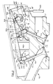
- FIG. 1 shows in cross-section, a cylinder head 10 with inlet valve 11 and exhaust valve 12, each valve slidably located in a valve guide 13.
- the valves 11 and 12 comprise a valve stem 14 which engages the valve guide 13 and a valve head 15 which is arranged to engage against a valve seat 16 to close a port 17.
- a valve lever 20 is pivotally mounted at one end on pivot 21.
- a ball formation 22 on the end of valve stem 14 engages in the complementary formation 23 on the end of valve lever 20 remote from the pivot 21, so as to permit limited pivotal movement between the valve member 20 and valve stem 14.
- Means is also provided to accommodate thermal expansion of the valve stem 14.
- a track 25 is provided on the valve lever 20, said track 25 having an arcuate portion 26 and a linear portion 27.
- a first link 30 is pivotally mounted at one end about a fixed pivot 31.
- a drive pin 32 is mounted on the other end of link 30, the drive pin 32 engaging in the track 25.
- the separation between the drive pin 32 and pivot 31 is equal to the radius of the arcuate portion 26 of the track 25 and the pivot 31 is located such that when the valve 11 is closed, the pin 32 will move freely around the arcuate portion 26 of the track 25.
- a second link 40 is pivotally mounted at one end about a pivot 41.
- An intermediate link 45 is pivotally connected at one end to the end of link 40 remote from pivot 41, by means of a pivot 46 and at the other end to the end of link 30 which carries a drive pin 32.
- a crankshaft 50 is mounted between the links 30 and 40 and a crank 51 thereon is connected to pivot 46 by drive link 52.
- Rotation of the crankshaft 50 which may be driven in suitable manner from the engine in the direction indicated by arrow M, will thus cause the linkage 52, 40, 45, 30 to oscillate causing drive pin 32 to reciprocate along an arcuate path defined by link 30.
- the linkage 52, 40, 45, 30 While the pin 32 engages the arcuate portion 26 of track 25, the valve 11 will remain closed. However, when the pin engages the linear portion 27 of the track 25, the lever will be moved to open and then close the valve 11.
- the opening and closing point of the valve 11 will correspond to when the drive pin 32 is located at the junction of the arcuate portion 26 and linear portion 27 of track 25.
- Means 55 is provided for adjusting the position of the pivot 41, said adjustment being axially of the link 40 when the linkage 40, 45, 30 is positioned such that the valve 11 is at its opening or closing point. Adjustment of the position of pivot 41 in this manner, will adjust the position of crank 51 relative to the opening and closing point of the valve 11 and thus vary the timing of duration of opening of the valve 11.
- pivot 46 will move down the arc X-X to point Y′ and the corresponding positions of crank 51 will move to O ⁇ and C ⁇ .
- the duration of opening of the valve is thus extended, the opening point O being advanced slightly, while the closing point C is retarded to a relatively significant degree.
- the basic timing of opening and closing of valve 11, the duration of opening and degree of opening are controlled by the geometry of the linkage 30, 40, 45, throw of crank 51 and geometry of lever 20 and the track 25 therein. Variation of this basic timing is achieved by movement of the pivot 41, which will preferably be controlled in response to engine speed in suitable manner, for example by hydraulic or screw adjustment means.
- variation in duration of opening of an inlet valve is achieved by variation of the closing point while the opening point remains substantially constant.
- the opening point of inlet valve 11 is preferably varied by up to 20 degrees, while the closing point may be varied by up to 60 degrees.
- the angle subtended between the intermediate link 45 and drive link 52, when inlet valve 11 is at its opening point is preferably less than 20 degrees.
- Variation in the duration of opening of the exhaust valve is not so critical and the exhaust valve timing may be fixed. However, when it is desirable to vary the timing of the exhaust valve this is preferably done by maintaining the closing point substantially constant and advancing or retarding the opening point.
- the opening point of the exhaust valve is preferably varied by up to 60 degrees and the closing point varied by up to 20 degrees, the angle subtended between the intermediate link 45 and drive link 52, when the exhaust valve is at its closing point preferably being less than 20 degrees.
- the crankshaft 50 may be arranged to control the inlet valves 11 and exhaust valves 12 of other cylinders of the engine through similar mechanisms, the cranks 51 being arranged to provide appropriate phase relationship between the valves. While the inlet valve 11 and exhaust valve 12 of each cylinder may be controlled by similar mechanisms, the variation in timing will normally be different. If it is not necessary to vary the timing of the exhaust valve, the pivot 41 of the mechanism controlling the exhaust valve may be fixed.
- the inlet and exhaust valves 11, 12 may be controlled by a common crank 51 as illustrated in Figure 2.
- the crankshaft 50 is located on the outside of exhaust valve 12.
- the crank 51 is drivingly connected to the inlet valve 11 in the manner illustrated in Figure 1, the valve lever 20 being pivotally supported by post 60 positioned between the valves 11 and 12.
- the pivot 41 for link 40 is provided at one end of an arm 61 which may be pivotted about pivot 62, by suitable means 63, to vary the position of the pivot 41 and thereby vary the timing of the inlet valve 11, as described above.
- a second valve lever 20′ is also pivotally attached at one end to the post 60 and is attached to the stem 14 of exhaust valve 12, in similar manner to that in which the inlet valve 11 is attached to valve lever 20.
- the second valve lever 20′ defines a track 25′ similar to that defined by lever 20.
- a drive pin 32′ engages in the track 25′, the drive pin 32′ being mounted at one end of a link 30′, the other end of link 30′ being pivotally mounted about a fixed pivot 31′, so that the drive pin 32′ is constrained to move along an arcuate path.
- the link 30′ is pivotally connected coaxially of the pin 32′ to one end of a link 65, the other end of the link 65 being pivotally connected to an extension of the drive link 52 by pivot 66.
- the pivot 66 will describe an ovoid path P which will cause the pin 32′ to move in reciprocating motion in the track 25, opening and closing the exhaust valve 12.
- the inlet valve 11 is opened and closed in similar manner, as described above.
- pins 32 and 32′ will move in the same direction while the tracks 25 and 25′ are reversed, one valve 11, 12 will be opening as the other valve 12, 11 and closes and vice versa.
- the relative timing of the inlet and exhaust valves 11 and 12 may be set as desired, by suitable design of the geometry of the linkage mechanism.
- intermediate link 45 is connected to the first link 30 at an point coincident with drive pin 32 and the drive link 52 is connected to the second link 40 at a point coincident with the connection to the intermediate link 45
- these connections may be separated in order to provide amplification of movement where desired.
- the drive link 52 may be connected directly to the intermediate link 45 at a point adjacent the connection between the intermediate link 45 and second link 40.
Landscapes
- Engineering & Computer Science (AREA)
- Mechanical Engineering (AREA)
- General Engineering & Computer Science (AREA)
- Valve Device For Special Equipments (AREA)
- Mechanically-Actuated Valves (AREA)
- Valve-Gear Or Valve Arrangements (AREA)
Applications Claiming Priority (2)
| Application Number | Priority Date | Filing Date | Title |
|---|---|---|---|
| GB8920361 | 1989-09-08 | ||
| GB898920361A GB8920361D0 (en) | 1989-09-08 | 1989-09-08 | Valve mechanisms |
Publications (1)
| Publication Number | Publication Date |
|---|---|
| EP0416794A1 true EP0416794A1 (fr) | 1991-03-13 |
Family
ID=10662770
Family Applications (1)
| Application Number | Title | Priority Date | Filing Date |
|---|---|---|---|
| EP90309371A Withdrawn EP0416794A1 (fr) | 1989-09-08 | 1990-08-28 | Commandes de soupape |
Country Status (4)
| Country | Link |
|---|---|
| US (1) | US5016581A (fr) |
| EP (1) | EP0416794A1 (fr) |
| JP (1) | JPH03100310A (fr) |
| GB (1) | GB8920361D0 (fr) |
Cited By (4)
| Publication number | Priority date | Publication date | Assignee | Title |
|---|---|---|---|---|
| EP1039103A3 (fr) * | 1999-03-26 | 2001-09-26 | Bayerische Motoren Werke Aktiengesellschaft | Dispositif pour varier la levée de soupape dans une culasse de moteur à combustion interne |
| GB2372071A (en) * | 2000-11-29 | 2002-08-14 | Bryan Nigel Victor Parsons | Desmodromic valve mechanism |
| WO2008149316A3 (fr) * | 2007-06-07 | 2009-03-12 | Manousos Pattakos | Actionnement de soupape variable desmodromique |
| WO2019130364A1 (fr) | 2017-12-29 | 2019-07-04 | Carlo Giacone | Système de commande, d'entraînement et de vérification pour vannes de machine |
Families Citing this family (13)
| Publication number | Priority date | Publication date | Assignee | Title |
|---|---|---|---|---|
| FR2705972B1 (fr) * | 1993-06-03 | 1995-07-21 | Staubli Sa Ets | Dispositif amortisseur pour machine à tisser. |
| US5791306A (en) * | 1997-08-13 | 1998-08-11 | Caterpillar Inc. | Internal combustion engine speed-throttle control |
| US6244228B1 (en) * | 1998-12-11 | 2001-06-12 | Damon Kuhn | Rotary-to-linear motion converter and use thereof |
| US7082912B2 (en) * | 2001-03-16 | 2006-08-01 | Folino Frank A | System and method for controlling engine valve lift and valve opening percentage |
| US6619250B2 (en) | 2001-03-16 | 2003-09-16 | Frank A. Folino | Desmodromic valve actuation system |
| US6953014B2 (en) * | 2001-03-16 | 2005-10-11 | Folino Frank A | Thermal compensating desmodromic valve actuation system |
| US6491008B1 (en) * | 2001-10-18 | 2002-12-10 | Ford Global Technologies, Inc. | Variable valve timing adjustable roller rocker arm assembly |
| BE1016217A5 (nl) * | 2004-09-28 | 2006-05-02 | Wiele Michel Van De Nv | Gaapvormingsinrichting en weefmachine voorzien van dergelijke gaapvormingsinrichting. |
| US8033261B1 (en) | 2008-11-03 | 2011-10-11 | Robbins Warren H | Valve actuation system and related methods |
| US9086171B2 (en) | 2012-11-15 | 2015-07-21 | Ken Meyer | KUSC positive return valve action |
| DE102016222280A1 (de) * | 2016-11-14 | 2018-05-17 | Man Diesel & Turbo Se | Gaswechselventil für eine Brennkraftmaschine und Brennkraftmaschine |
| EP3789645A1 (fr) * | 2019-09-03 | 2021-03-10 | HUSCO Automotive Holdings LLC | Systèmes et procédés pour un ensemble soupape-champignon |
| RU2730196C1 (ru) * | 2020-02-16 | 2020-08-19 | Владимир Витальевич Килин | Десмодромный кулачковый привод клапана газораспределительного механизма с регулировкой степени открытия клапана |
Citations (3)
| Publication number | Priority date | Publication date | Assignee | Title |
|---|---|---|---|---|
| GB520733A (en) * | 1938-10-28 | 1940-05-02 | Thomas Evenson | Mechanism for converting rotary motion into an oscillatory or rocking movement |
| US2954017A (en) * | 1958-03-29 | 1960-09-27 | Porsche Kg | Valve control arrangement for internal combustion engines |
| EP0311282A2 (fr) * | 1987-10-03 | 1989-04-12 | Jaguar Cars Limited | Commandes de soupape |
Family Cites Families (8)
| Publication number | Priority date | Publication date | Assignee | Title |
|---|---|---|---|---|
| US1586188A (en) * | 1921-03-31 | 1926-05-25 | Robert F Fisher | Internal-combustion engine |
| US1503384A (en) * | 1921-11-28 | 1924-07-29 | Edgar S Sewell | Valve gear for internal-combustion engines |
| GB420032A (en) * | 1932-12-15 | 1934-11-23 | Goetaverken Ab | Improvements in controlling means for varying the exhaust valve timing of two-strokecompression ignition engines |
| US2035166A (en) * | 1935-03-16 | 1936-03-24 | Ruggles Klingemann Mfg Company | Throttle valve |
| US2035222A (en) * | 1936-01-09 | 1936-03-24 | Charles G Curtis | Poppet valve gear for internal combustion or other engines |
| JPS50144925A (fr) * | 1974-05-11 | 1975-11-21 | ||
| US4457268A (en) * | 1982-01-25 | 1984-07-03 | Jones Darrell L | Valve position control device |
| LU84890A1 (fr) * | 1983-06-29 | 1985-03-29 | Wurth Paul Sa | Mecanisme pour actionner un clapet de dosage |
-
1989
- 1989-09-08 GB GB898920361A patent/GB8920361D0/en active Pending
-
1990
- 1990-08-28 EP EP90309371A patent/EP0416794A1/fr not_active Withdrawn
- 1990-09-06 US US07/578,785 patent/US5016581A/en not_active Expired - Fee Related
- 1990-09-07 JP JP2236014A patent/JPH03100310A/ja active Pending
Patent Citations (3)
| Publication number | Priority date | Publication date | Assignee | Title |
|---|---|---|---|---|
| GB520733A (en) * | 1938-10-28 | 1940-05-02 | Thomas Evenson | Mechanism for converting rotary motion into an oscillatory or rocking movement |
| US2954017A (en) * | 1958-03-29 | 1960-09-27 | Porsche Kg | Valve control arrangement for internal combustion engines |
| EP0311282A2 (fr) * | 1987-10-03 | 1989-04-12 | Jaguar Cars Limited | Commandes de soupape |
Cited By (4)
| Publication number | Priority date | Publication date | Assignee | Title |
|---|---|---|---|---|
| EP1039103A3 (fr) * | 1999-03-26 | 2001-09-26 | Bayerische Motoren Werke Aktiengesellschaft | Dispositif pour varier la levée de soupape dans une culasse de moteur à combustion interne |
| GB2372071A (en) * | 2000-11-29 | 2002-08-14 | Bryan Nigel Victor Parsons | Desmodromic valve mechanism |
| WO2008149316A3 (fr) * | 2007-06-07 | 2009-03-12 | Manousos Pattakos | Actionnement de soupape variable desmodromique |
| WO2019130364A1 (fr) | 2017-12-29 | 2019-07-04 | Carlo Giacone | Système de commande, d'entraînement et de vérification pour vannes de machine |
Also Published As
| Publication number | Publication date |
|---|---|
| JPH03100310A (ja) | 1991-04-25 |
| US5016581A (en) | 1991-05-21 |
| GB8920361D0 (en) | 1989-10-25 |
Similar Documents
| Publication | Publication Date | Title |
|---|---|---|
| US5016581A (en) | Valve mechanisms | |
| US4723516A (en) | Valve open duration and timing controller | |
| US6357405B1 (en) | Valve drive mechanism of four-stroke cycle engine | |
| US4530318A (en) | Intake and exhaust valve system for internal combustion engine | |
| EP0213759B1 (fr) | Mécanisme de fonctionnement de soupape | |
| JP2814613B2 (ja) | エンジンの弁作動装置 | |
| EP0311282B1 (fr) | Commandes de soupape | |
| CA1074197A (fr) | Mecanismes de reglage de distribution | |
| US20010037781A1 (en) | Variable valve mechanism having an eccentric-driven frame | |
| US4791893A (en) | Valve train arrangement for multi-valve engine | |
| US5787849A (en) | Valve timing phase changer | |
| EP0963508B1 (fr) | Mecanisme de reglage de soupapes | |
| EP0601570B1 (fr) | Commande de soupape pour moteur à combustion interne | |
| JP2703014B2 (ja) | 2‐ストロークサイクルエンジンの排気コントロールバルブ及び該バルブを使用する方法 | |
| US4836155A (en) | Variable duration valve opening mechanism | |
| US7117831B2 (en) | Engine with variable lift valve mechanism | |
| EP0434331A1 (fr) | Dispositif d'entraînement de soupapes pour moteur à combustion interne | |
| US6360705B1 (en) | Mechanism for variable valve lift and cylinder deactivation | |
| US4594972A (en) | Valve mechanism | |
| KR940007351A (ko) | 엔진의 밸브구동장치 | |
| JP4123879B2 (ja) | 可変動弁装置 | |
| JPH06280523A (ja) | 内燃機関の動弁装置 | |
| KR200161579Y1 (ko) | 자동차용 기관의 밸브 개폐 기구 | |
| KR101241595B1 (ko) | 가변 밸브타이밍 장치 | |
| JPH0543204Y2 (fr) |
Legal Events
| Date | Code | Title | Description |
|---|---|---|---|
| PUAI | Public reference made under article 153(3) epc to a published international application that has entered the european phase |
Free format text: ORIGINAL CODE: 0009012 |
|
| AK | Designated contracting states |
Kind code of ref document: A1 Designated state(s): DE FR GB IT SE |
|
| 17P | Request for examination filed |
Effective date: 19910829 |
|
| 17Q | First examination report despatched |
Effective date: 19920921 |
|
| STAA | Information on the status of an ep patent application or granted ep patent |
Free format text: STATUS: THE APPLICATION IS DEEMED TO BE WITHDRAWN |
|
| 18D | Application deemed to be withdrawn |
Effective date: 19930301 |