EP0416948B1 - Variable nozzle for a radial turbine - Google Patents
Variable nozzle for a radial turbine Download PDFInfo
- Publication number
- EP0416948B1 EP0416948B1 EP90309843A EP90309843A EP0416948B1 EP 0416948 B1 EP0416948 B1 EP 0416948B1 EP 90309843 A EP90309843 A EP 90309843A EP 90309843 A EP90309843 A EP 90309843A EP 0416948 B1 EP0416948 B1 EP 0416948B1
- Authority
- EP
- European Patent Office
- Prior art keywords
- platform
- blades
- periphery
- nozzle
- turbine nozzle
- Prior art date
- Legal status (The legal status is an assumption and is not a legal conclusion. Google has not performed a legal analysis and makes no representation as to the accuracy of the status listed.)
- Expired - Lifetime
Links
- 239000012530 fluid Substances 0.000 claims description 14
- 238000000034 method Methods 0.000 claims description 6
- 230000002093 peripheral effect Effects 0.000 claims description 3
- 230000000295 complement effect Effects 0.000 description 4
- 238000003754 machining Methods 0.000 description 4
- 230000000694 effects Effects 0.000 description 1
- 239000012634 fragment Substances 0.000 description 1
- 238000004519 manufacturing process Methods 0.000 description 1
- 125000006850 spacer group Chemical group 0.000 description 1
Images

Classifications
-
- F—MECHANICAL ENGINEERING; LIGHTING; HEATING; WEAPONS; BLASTING
- F01—MACHINES OR ENGINES IN GENERAL; ENGINE PLANTS IN GENERAL; STEAM ENGINES
- F01D—NON-POSITIVE DISPLACEMENT MACHINES OR ENGINES, e.g. STEAM TURBINES
- F01D9/00—Stators
- F01D9/02—Nozzles; Nozzle boxes; Stator blades; Guide conduits, e.g. individual nozzles
-
- F—MECHANICAL ENGINEERING; LIGHTING; HEATING; WEAPONS; BLASTING
- F01—MACHINES OR ENGINES IN GENERAL; ENGINE PLANTS IN GENERAL; STEAM ENGINES
- F01D—NON-POSITIVE DISPLACEMENT MACHINES OR ENGINES, e.g. STEAM TURBINES
- F01D9/00—Stators
- F01D9/02—Nozzles; Nozzle boxes; Stator blades; Guide conduits, e.g. individual nozzles
- F01D9/04—Nozzles; Nozzle boxes; Stator blades; Guide conduits, e.g. individual nozzles forming ring or sector
- F01D9/048—Nozzles; Nozzle boxes; Stator blades; Guide conduits, e.g. individual nozzles forming ring or sector for radial admission
-
- F—MECHANICAL ENGINEERING; LIGHTING; HEATING; WEAPONS; BLASTING
- F01—MACHINES OR ENGINES IN GENERAL; ENGINE PLANTS IN GENERAL; STEAM ENGINES
- F01D—NON-POSITIVE DISPLACEMENT MACHINES OR ENGINES, e.g. STEAM TURBINES
- F01D9/00—Stators
- F01D9/02—Nozzles; Nozzle boxes; Stator blades; Guide conduits, e.g. individual nozzles
- F01D9/04—Nozzles; Nozzle boxes; Stator blades; Guide conduits, e.g. individual nozzles forming ring or sector
- F01D9/045—Nozzles; Nozzle boxes; Stator blades; Guide conduits, e.g. individual nozzles forming ring or sector for radial flow machines or engines
Definitions
- This invention relates to fluid turbines, and in particular to (a) turbine nozzles, and (b) a method of varying the power of such nozzles.
- Fluid turbines for example, compressed air turbines
- a way of satisfying differing power requirements is to configure the nozzles thereof with differing numbers of blades. That is, for given circumstances, a nozzle can be formed with X number of blades for maximum power, X/2 for half power, and X/4 for one-quarter power.
- a nozzle ring, having at the inlet a throttle ring which is adjustable during operation, is known from DE-C-154 817.
- a turbine nozzle having a platform having a periphery defining a substantially circular shape; a plurality of equally spaced blades having leading and trailing edges arrayed on said platform, adjacent to said periphery and defining a plurality of nozzle passages; and characterized by means formed about portions of the periphery of said platform, integral with the leading edges of sequential ones of said blades, for preventing a flow of fluid through said nozzle passages.
- a method of increasing the power of a turbine nozzle including the steps of providing a turbine nozzle which includes a platform having a periphery defining a substantially circular shape, a plurality of equally spaced blades having leading and trailing edges arrayed on the periphery of said platform and defining a plurality of nozzle passages adjacent to said periphery, and characterized by a peripheral wall integral with said leading edges of said blades, for preventing a flow of fluid through said nozzle passages; and by removing portions of said wall to permit fluid flow through sequential ones of said nozzle passages.
- an end plate 10 for a compressed air turbine comprises a platform 12 which has two sets 14 and 16 of blades 18 thereon.
- the blades 18 extend from the platform 12 in a normal attitude thereto.
- a rotor shaft seal 20 is received in the central recess 22 in the platform 12 and a bladed rotor 24 is set into the seal.
- An O-ring seal 26 sets against the end plate 10, and a spacer 28, for a complementary end plate (not shown), only a fragment thereof being shown, is interposed between end plate 10 and the complementary end plate.
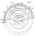
- the platform 12 as can be seen in Figures 1 and 2, has a full complement of blades 18. Accordingly, the blades and platform, comprising a nozzle 30, is bladed for full power. However, a pair of walls 32 and 34 are coupled to the periphery of nozzle 30, in proximate adjacency to sets 38 and 40 of blades 18. The walls 32 and 34, describing arcs of equal length, inhibit a fluid flow through the sets of blades 38 and 40. The arc lengths of the walls 32 and 34 are formed by machining away portions of the as cast wall which completely circumscribes the platform 12.
- the walls 32 and 34 having heights from the platform 12 substantially the same as the heights of the blades 18 (as can be perceived in Figure 1), are each of approximately ninety degrees of arc.
- machining away the walls in their entirety will provide a nozzle 30 capable of full power.
- machining away half -- complementary halves -- of each of the walls 32 and 34 will render the nozzle capable of approximately three-quarters of its full power potential.
- Fully complemented-bladed nozzles can be formed with walls, like the walls 32 and 34, which circumscribe half, three-quarters, one-quarter, etc., as one chooses, of the blades 18. Then, by the expedient of machining away so much of the walls as will power the nozzle to the level required, a large number of power levels can be provided, even by going as far as removing the walls entirely.
Landscapes
- Engineering & Computer Science (AREA)
- Mechanical Engineering (AREA)
- General Engineering & Computer Science (AREA)
- Turbine Rotor Nozzle Sealing (AREA)
- Control Of Turbines (AREA)
Applications Claiming Priority (2)
| Application Number | Priority Date | Filing Date | Title |
|---|---|---|---|
| US07/403,818 US5102296A (en) | 1989-09-07 | 1989-09-07 | Turbine nozzle, and a method of varying the power of same |
| US403818 | 1989-09-07 |
Publications (2)
| Publication Number | Publication Date |
|---|---|
| EP0416948A1 EP0416948A1 (en) | 1991-03-13 |
| EP0416948B1 true EP0416948B1 (en) | 1993-11-10 |
Family
ID=23597107
Family Applications (1)
| Application Number | Title | Priority Date | Filing Date |
|---|---|---|---|
| EP90309843A Expired - Lifetime EP0416948B1 (en) | 1989-09-07 | 1990-09-07 | Variable nozzle for a radial turbine |
Country Status (9)
| Country | Link |
|---|---|
| US (1) | US5102296A (da) |
| EP (1) | EP0416948B1 (da) |
| JP (1) | JP3091763B2 (da) |
| KR (1) | KR0160131B1 (da) |
| AU (1) | AU624530B2 (da) |
| CA (1) | CA2024786C (da) |
| DE (1) | DE69004533T2 (da) |
| DK (1) | DK170998B1 (da) |
| SE (1) | SE470067B (da) |
Families Citing this family (9)
| Publication number | Priority date | Publication date | Assignee | Title |
|---|---|---|---|---|
| US5443362A (en) * | 1994-03-16 | 1995-08-22 | The Hoover Company | Air turbine |
| US6077032A (en) * | 1998-07-16 | 2000-06-20 | Felchar Manufacturing Corporation | Housing assembly for a vacuum cleaner |
| ES2222930T3 (es) | 1999-10-05 | 2005-02-16 | Access Business Group International Llc | Produccion de energia hidraulica para sistema de tratamiento de las aguas. |
| US6885114B2 (en) | 1999-10-05 | 2005-04-26 | Access Business Group International, Llc | Miniature hydro-power generation system |
| DE10330352B4 (de) * | 2003-07-05 | 2008-03-20 | Man Diesel Se | Verfahren und Vorrichtungen zum Betrieb von Hubkolbenbrennkraftmaschinen |
| US7675188B2 (en) * | 2003-10-09 | 2010-03-09 | Access Business Group International, Llc | Miniature hydro-power generation system |
| KR20070022495A (ko) * | 2005-08-22 | 2007-02-27 | 허태복 | 응축기능을 갖는 팽창터빈 |
| WO2007024064A1 (en) * | 2005-08-22 | 2007-03-01 | Nam-Sik Ju | Power generation apparatus and method using turbine |
| JP7393339B2 (ja) | 2018-03-06 | 2023-12-06 | インディアナ ユニバーシティー リサーチ アンド テクノロジー コーポレーション | 血圧駆動補助ポンプ |
Family Cites Families (10)
| Publication number | Priority date | Publication date | Assignee | Title |
|---|---|---|---|---|
| DE154817C (da) * | 1903-03-13 | |||
| US768116A (en) * | 1903-10-07 | 1904-08-23 | W L Cook | Steam-turbine. |
| US980503A (en) * | 1910-05-31 | 1911-01-03 | Ellis F Edgar | Steam-turbine. |
| US1641665A (en) * | 1925-11-21 | 1927-09-06 | Gen Electric | Turbine-nozzle diaphragm |
| US2331076A (en) * | 1939-05-11 | 1943-10-05 | Bbc Brown Boveri & Cie | Turbine nozzle ring |
| DE1118801B (de) * | 1959-09-26 | 1961-12-07 | Kloeckner Humboldt Deutz Ag | Einrichtung zur Verhuetung von Schwingungsbruechen an Laufschaufeln von teilbeaufschlagten Turbinen |
| CH428774A (de) * | 1964-04-15 | 1967-01-31 | Linde Ag | Leitschaufelkranz für Entspannungsturbinen |
| US3909157A (en) * | 1972-01-27 | 1975-09-30 | Chromalloy American Corp | Turbine nozzle-vane construction |
| JPH0659502B2 (ja) * | 1987-03-26 | 1994-08-10 | 宇宙科学研究所長 | ロケット用高圧燃焼器の燃焼室及びその製造方法 |
| US4780057A (en) * | 1987-05-15 | 1988-10-25 | Westinghouse Electric Corp. | Partial arc steam turbine |
-
1989
- 1989-09-07 US US07/403,818 patent/US5102296A/en not_active Expired - Lifetime
-
1990
- 1990-09-05 AU AU62230/90A patent/AU624530B2/en not_active Ceased
- 1990-09-06 DK DK213890A patent/DK170998B1/da not_active IP Right Cessation
- 1990-09-06 KR KR1019900014071A patent/KR0160131B1/ko not_active Expired - Fee Related
- 1990-09-06 CA CA002024786A patent/CA2024786C/en not_active Expired - Fee Related
- 1990-09-07 EP EP90309843A patent/EP0416948B1/en not_active Expired - Lifetime
- 1990-09-07 JP JP02238850A patent/JP3091763B2/ja not_active Expired - Fee Related
- 1990-09-07 DE DE90309843T patent/DE69004533T2/de not_active Expired - Fee Related
- 1990-09-07 SE SE9002859A patent/SE470067B/sv unknown
Also Published As
| Publication number | Publication date |
|---|---|
| DE69004533D1 (de) | 1993-12-16 |
| CA2024786A1 (en) | 1991-03-08 |
| DK213890D0 (da) | 1990-09-06 |
| CA2024786C (en) | 1994-12-13 |
| DK170998B1 (da) | 1996-04-15 |
| SE9002859D0 (sv) | 1990-09-07 |
| AU6223090A (en) | 1991-03-14 |
| KR910006598A (ko) | 1991-04-29 |
| DE69004533T2 (de) | 1994-05-11 |
| US5102296A (en) | 1992-04-07 |
| KR0160131B1 (ko) | 1999-01-15 |
| JP3091763B2 (ja) | 2000-09-25 |
| SE9002859L (sv) | 1991-03-08 |
| SE470067B (sv) | 1993-11-01 |
| DK213890A (da) | 1991-03-08 |
| EP0416948A1 (en) | 1991-03-13 |
| JPH03172503A (ja) | 1991-07-25 |
| AU624530B2 (en) | 1992-06-11 |
Similar Documents
| Publication | Publication Date | Title |
|---|---|---|
| EP1312759B1 (en) | Steam turbine inlet and methods of retrofitting | |
| EP0795688B1 (en) | Centrifugal Fluid Assembly | |
| EP0416948B1 (en) | Variable nozzle for a radial turbine | |
| EP1662091B1 (en) | Multiform film cooling holes | |
| EP2948641B1 (en) | Seal assembly in a gas turbine engine including grooves in a radially outwardly facing side of a platform and in a inwardly facing side of an inner shroud | |
| US6602049B2 (en) | Compressor stator having a constant clearance | |
| EP1225304B1 (en) | Nozzle fillet backside cooling | |
| EP1502682A1 (en) | Manufacturing method especially for integrally bladed rotors | |
| JPH1085977A5 (da) | ||
| EP2249043A2 (de) | Strömungsarbeitsmaschine mit Fluidentnahme | |
| DE102004055439A1 (de) | Strömungsarbeitsmaschine mit dynamischer Strömungsbeeinflussung | |
| CA2434213A1 (en) | A turbine engine | |
| EP0733807B2 (en) | Multistage centrifugal compressor | |
| EP3277931B1 (en) | Turbine blade trailing edge with low flow framing channel | |
| WO1993011355A1 (en) | Automotive fuel pump with modular pump housing | |
| EP1895097A2 (en) | Low stress turbine bucket | |
| CA2363363A1 (en) | Cooling system for gas turbine stator nozzles | |
| EP0864758B1 (en) | Impeller for turbine pumps provided with vanes having an improved profile | |
| MY110847A (en) | Centrifugal fan and manufacturing method thereof and appararus having centrifugal fan. | |
| JP4171580B2 (ja) | ポンプインペラおよびその修正方法 | |
| US7713023B2 (en) | Steam turbine nozzle box and methods of fabricating | |
| JPS54105307A (en) | Electric fan | |
| JPH08200005A (ja) | 羽根付きロータ | |
| EP0080258A3 (en) | Radial flow turbine rotor | |
| JPS58162702A (ja) | 軸流タ−ボ機械 |
Legal Events
| Date | Code | Title | Description |
|---|---|---|---|
| PUAI | Public reference made under article 153(3) epc to a published international application that has entered the european phase |
Free format text: ORIGINAL CODE: 0009012 |
|
| AK | Designated contracting states |
Kind code of ref document: A1 Designated state(s): DE FR GB IT |
|
| 17P | Request for examination filed |
Effective date: 19910906 |
|
| 17Q | First examination report despatched |
Effective date: 19921208 |
|
| GRAA | (expected) grant |
Free format text: ORIGINAL CODE: 0009210 |
|
| AK | Designated contracting states |
Kind code of ref document: B1 Designated state(s): DE FR GB IT |
|
| REF | Corresponds to: |
Ref document number: 69004533 Country of ref document: DE Date of ref document: 19931216 |
|
| ITF | It: translation for a ep patent filed | ||
| ET | Fr: translation filed | ||
| PLBE | No opposition filed within time limit |
Free format text: ORIGINAL CODE: 0009261 |
|
| STAA | Information on the status of an ep patent application or granted ep patent |
Free format text: STATUS: NO OPPOSITION FILED WITHIN TIME LIMIT |
|
| 26N | No opposition filed | ||
| REG | Reference to a national code |
Ref country code: GB Ref legal event code: IF02 |
|
| PGFP | Annual fee paid to national office [announced via postgrant information from national office to epo] |
Ref country code: GB Payment date: 20070926 Year of fee payment: 18 |
|
| PGFP | Annual fee paid to national office [announced via postgrant information from national office to epo] |
Ref country code: DE Payment date: 20071031 Year of fee payment: 18 Ref country code: IT Payment date: 20070927 Year of fee payment: 18 |
|
| PGFP | Annual fee paid to national office [announced via postgrant information from national office to epo] |
Ref country code: FR Payment date: 20070917 Year of fee payment: 18 |
|
| GBPC | Gb: european patent ceased through non-payment of renewal fee |
Effective date: 20080907 |
|
| REG | Reference to a national code |
Ref country code: FR Ref legal event code: ST Effective date: 20090529 |
|
| PG25 | Lapsed in a contracting state [announced via postgrant information from national office to epo] |
Ref country code: IT Free format text: LAPSE BECAUSE OF NON-PAYMENT OF DUE FEES Effective date: 20080907 Ref country code: DE Free format text: LAPSE BECAUSE OF NON-PAYMENT OF DUE FEES Effective date: 20090401 |
|
| PG25 | Lapsed in a contracting state [announced via postgrant information from national office to epo] |
Ref country code: FR Free format text: LAPSE BECAUSE OF NON-PAYMENT OF DUE FEES Effective date: 20080930 |
|
| PG25 | Lapsed in a contracting state [announced via postgrant information from national office to epo] |
Ref country code: GB Free format text: LAPSE BECAUSE OF NON-PAYMENT OF DUE FEES Effective date: 20080907 |