EP0416970A2 - Verfahren und Vorrichtung zur Signalstabilisierung und Eichung für Kernspektroskopie - Google Patents
Verfahren und Vorrichtung zur Signalstabilisierung und Eichung für Kernspektroskopie Download PDFInfo
- Publication number
- EP0416970A2 EP0416970A2 EP90402278A EP90402278A EP0416970A2 EP 0416970 A2 EP0416970 A2 EP 0416970A2 EP 90402278 A EP90402278 A EP 90402278A EP 90402278 A EP90402278 A EP 90402278A EP 0416970 A2 EP0416970 A2 EP 0416970A2
- Authority
- EP
- European Patent Office
- Prior art keywords
- spectrum
- energy
- coincident
- detectors
- nuclear
- Prior art date
- Legal status (The legal status is an assumption and is not a legal conclusion. Google has not performed a legal analysis and makes no representation as to the accuracy of the status listed.)
- Withdrawn
Links
Images

Classifications
-
- G—PHYSICS
- G01—MEASURING; TESTING
- G01T—MEASUREMENT OF NUCLEAR OR X-RADIATION
- G01T1/00—Measuring X-radiation, gamma radiation, corpuscular radiation, or cosmic radiation
- G01T1/36—Measuring spectral distribution of X-rays or of nuclear radiation spectrometry
- G01T1/40—Stabilisation of spectrometers
-
- G—PHYSICS
- G01—MEASURING; TESTING
- G01V—GEOPHYSICS; GRAVITATIONAL MEASUREMENTS; DETECTING MASSES OR OBJECTS; TAGS
- G01V5/00—Prospecting or detecting by the use of ionising radiation, e.g. of natural or induced radioactivity
- G01V5/04—Prospecting or detecting by the use of ionising radiation, e.g. of natural or induced radioactivity specially adapted for well-logging
- G01V5/06—Prospecting or detecting by the use of ionising radiation, e.g. of natural or induced radioactivity specially adapted for well-logging for detecting naturally radioactive minerals
-
- G—PHYSICS
- G01—MEASURING; TESTING
- G01V—GEOPHYSICS; GRAVITATIONAL MEASUREMENTS; DETECTING MASSES OR OBJECTS; TAGS
- G01V5/00—Prospecting or detecting by the use of ionising radiation, e.g. of natural or induced radioactivity
- G01V5/04—Prospecting or detecting by the use of ionising radiation, e.g. of natural or induced radioactivity specially adapted for well-logging
- G01V5/08—Prospecting or detecting by the use of ionising radiation, e.g. of natural or induced radioactivity specially adapted for well-logging using primary nuclear radiation sources or X-rays
- G01V5/10—Prospecting or detecting by the use of ionising radiation, e.g. of natural or induced radioactivity specially adapted for well-logging using primary nuclear radiation sources or X-rays using neutron sources
- G01V5/101—Prospecting or detecting by the use of ionising radiation, e.g. of natural or induced radioactivity specially adapted for well-logging using primary nuclear radiation sources or X-rays using neutron sources and detecting the secondary Y-rays produced in the surrounding layers of the bore hole
-
- G—PHYSICS
- G01—MEASURING; TESTING
- G01V—GEOPHYSICS; GRAVITATIONAL MEASUREMENTS; DETECTING MASSES OR OBJECTS; TAGS
- G01V5/00—Prospecting or detecting by the use of ionising radiation, e.g. of natural or induced radioactivity
- G01V5/04—Prospecting or detecting by the use of ionising radiation, e.g. of natural or induced radioactivity specially adapted for well-logging
- G01V5/08—Prospecting or detecting by the use of ionising radiation, e.g. of natural or induced radioactivity specially adapted for well-logging using primary nuclear radiation sources or X-rays
- G01V5/12—Prospecting or detecting by the use of ionising radiation, e.g. of natural or induced radioactivity specially adapted for well-logging using primary nuclear radiation sources or X-rays using gamma or X-ray sources
Definitions
- the present invention relates to a method and an apparatus for the gain stabilization and the calibration of a signal issued from a nuclear detector device.
- Such devices are commonly used in many technical areas where measurements involve nuclear particles and radiation detection, one among others being e.g. the well logging techniques, wherein a tool is lowered in a well to carry out physical measurements.
- the nuclear spectroscopy tool by which energy spectra of the constituents of formation matrices and fluids are generated, more specifically in which gamma rays are detected, has been found to provide information of particular value in formation analysis.
- These gamma rays can be due to the natural radioactivity of the formations or result from the irradiation of these formations by a neutron or gamma ray source.
- the detection of these gamma rays, whether from natural or induced radioactivity, can be carried out separately for several distinct windows or energy ranges in order to obtain information on the energy spectrum of these gamma rays. Analysis of the obtained spectrum then furnishes information on the lithology of the formations.
- the detection system comprises a scintillation crystal, a photomultiplier, a linear amplifier and a pulse height analyzer.
- the pulse height analyzer the energy spectrum of the gamma rays is divided into five windows. The count rates of the different windows make it possible to calculate the thorium, uranium, and potassium (T,U,K,) contents of the formations. In this technique, as in all those using a spectral study i.e.
- a stabilization method frequently used, and described in the above mentioned patent consists of an auxiliary gamma ray source that emits a characteristic gamma ray whose energy is below the range of interest in the detected spectrum.
- an Americium source (Am 241) is chosen, the primary emission peak of which is located at 60 KeV.
- Two count rates M1 and N1 are measured in two windows of predetermined width located on each side of the 60 KeV energy and an error signal, which is a function of the difference (M1-N1), is used to control the high voltage of the photomultiplier through a negative feedback loop.
- the above described stabilization technique is suitable for those portions of the spectrum close to the emission peak.
- the spectrum energy scale is shifted by greater amounts at higher energies. Therefore, the detection of the shift at low energies is not entirely satisfactory for correcting shifts at higher energies and, due to statistical variations in the count rates, errors appear.
- the low energy gamma rays of the auxiliary source reach only a part of the crystal, which is all the more smaller when the crystal has high efficiency.
- the resulting stabilization is seriously affected by any crystal heterogeneity and/or temperature gradients in the crystal.
- the U.S. Pat. No. 3,101,409 proposes a stabilization using two peaks coming from two auxiliary gamma ray sources.
- One of the peaks is used to control the high voltage of the photomultiplier while the other peak is used to control the lower threshold of the pulse height discriminator.
- the two stabilization loops are independent and do not make it possible to solve the case in which one of the peaks in not present. In this patent, this problem is not addressed because the peaks come from two auxiliary monoenergetic gamma ray sources especially added to the apparatus for stabilization.
- a gain stabilization method is proposed wherein a reference radiation source (having a predetermined energy spectrum) is located adjacent to the scintillator.
- a reference signal representative of the relationship between the predetermined energy spectrum from the reference radiation source is produced.
- a gamma ray detection apparatus that includes a stabilization loop based upon the detection of several peaks at different energy levels located in the energy range of the detected spectrum.
- Discrimination means separates the electric pulses, representative of the gamma rays, the amplitudes of which fall within two first contiguous windows located on each side of a first predetermined value and within two second contiguous windows located on each side of a second predetermined value. These predetermined values correspond to two reference energies or peaks located in the detected spectrum of gamma rays coming from the formations.
- This known apparatus further includes another stabilization loop based upon an auxiliary gamma ray source the emission peak of which is located outside of the detected spectrum of the formations.
- This apparatus although being an improvement over the above mentioned apparatus, relies on high energy peaks which are part of the measurements themselves. Since these energy peaks have to be removed from the total energy spectrum, this decreases the reliability of the measurements.
- U.S. Patent 3,900,731 contemplates a method and apparatus for stabilizing the gain of a photomultiplier by compensating its variations through a modification of the illumination of its cathode.
- US patent 2,769,916 shows a neutron detecting device provided with two facing scintillation detectors between which is disposed a foil of neutron-gamma reactive material, i.e. able to produce, upon bombardment by an incident neutron, gamma rays, two of which are emitted simultaneously and thus detected simultaneously in both detectors.
- this device does not provide any gain stabilization.
- US patent 4,450,354 depicts a method for the natural gamma ray detection of the casing thickness in a cased well borehole, using an ancillary detector which is substantially smaller than the regular detector used for the measurements.
- the gain stabilization is achieved by using an ancillary nuclear source (Am 241) emitting practically simultaneously an alpha particle which is detected by the ancillary small detector, and a photon-gamma radiation of 60 Kev which is detected only by the regular large detector.
- Am 241 ancillary nuclear source
- a coincidence circuit each time an alpha particle and a photon-gamma are simultaneously detected, actuates a stabilizing circuit which increases or decreases the amplifier gain depending upon the actual energy (as measured) of the photon-gamma particle being below or above the theoretical energy value of 60 Kev.
- this method is not fully satisfactory.
- the reference energy peak is in the low part of the energy range.
- the ancillary source and the ancillary detector increases the complexity of the logging tool, thus the cost and size.
- the two detectors are different with regard to (i) size: one is small and the other is large, (ii) material: one detects alpha particle, the other detects gamma rays, and (iii) use: only one detector is sensitive to particles representative of the earth formation.
- the safety concern with respect to nuclear sources has indubitably increased over the years. Accordingly, the regulations have become more and more stringent. For example, the activity (measured in microCurie or nanoCurie) of the sources should not exceed a given value. It is, however, difficult to determine and find a nuclear source which complies with the regulations as well as the needs of the industry.
- US patent 3,633,030 shows a logging tool including means attempting to improve the energy resolution of the detector. It includes one or two NaI scintillator(s), disposed close to a semiconductor radiation detector which, upon receipt of a gamma ray coming from the formation, emits an electron and a positron. The positron produces two simultaneous, oppositely directed gamma rays, which are detected by each detectors. Scintillator signals are applied to a gating circuit which passes or inhibits the signal from the semiconductor detector, thus allowing delivery of a coincidence or anticoincidence spectrum. This device does not provide any gain stabilization, and is directed to the elimination of the Compton production radiation. Furthermore, the semiconductor requires thermal protection, which increases the costs.
- a second object of the invention is to propose a nuclear spectroscopy method and apparatus with an increased detection sensitivity.
- a spectroscopy method and apparatus including features for offset correction purpose.
- a nuclear spectroscopy method for the stabilization of an energy spectrum, made from a signal, emitted by a radiation detector, and containing nuclear events, represented by pulses, whose amplitude is a measure of the energy of the particles, such as gamma rays, collected by said radiation detector, said energy spectrum including at least a first reference energy peak coming from an ancillary nuclear source, wherein said method comprises the steps of:
- said ancillary nuclear source is placed between the respective facing ends of said two detectors.
- detectors are both made of bismuth germanate crystal, of the formula Bi4Ge3O12 (hereafter BGO).
- the nuclear activity of said ancillary source corresponds to a level which is substantially smaller than the activity level of the radiation under analysis.
- the method further includes, for each detector, establishing a non coincident spectrum representative of the non coincident events.
- the ancillary source is made of 22Na. Briefly, this source allows the simultaneous emission of (i) a positron which, by annihilation, emits a pair of opposed directions gamma rays of 0.511 Mev, and (ii) a 1.27 Mev gamma ray.
- the method includes a calibrating step (for offset correction purpose) using said first reference peak and a second reference energy peak.
- said second reference energy peak comes from said ancillary source.
- said first reference peak is at 0.511 MeV
- said second reference peak is at 1.78 MeV.
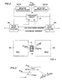
- a logging sonde 10 is shown suspended by an armored cable 12 in a borehole 14 surrounded by earth formations 16.
- a depth measuring device 13, disposed close to the surface, is associated in the usual manner to the cable 12 and to a surface recorder 11.
- the cable 12 includes, between the output of the sonde 10 and the surface recorder 11, a first link 12A, a second link 12B and a third link 12C.
- the nuclear measurements carried out in the sonde, as a function of depth, are transmitted along the cable 12 towards the surface recorder 11, successively via surface cable link 12A, a receiver 15, and a spectrum memory/plotter 17.
- Said memory/plotter 17 is connected to said recorder 11 via a line I corresponding to coincident spectra and a line II corresponding to non coincident spectra.
- the second link 12B is connected to line I at the output of the spectrum memory/plotter 17, and includes successively, a gain control unit 19, a modulator 21 and a high voltage control unit 23.
- the third link 12C is connected to said line I and comprises an offset control unit 25. It is meant here by "memory/plotter” a device designed to count and record (or memorize) counts so as to establish the corresponding energy spectrum.
- downhole devices including a first nuclear detector 100 associated to a first photomultiplier 101, which output feeds a first pulse height analyzer 102 linked to a transmitter 22 allowing transmission of data through cable 12.
- the downhole devices, inside the sonde 10 also comprise a second nuclear detector 200 associated to a second photomultiplier 201 feeding a second pulse height analyzer 202 itself also linked to the transmitter 22.
- the outputs of the respective photomultipliers 101, 201 are connected to a coincidence circuit 20, itself linked to additional inputs respectively provided in the first and second pulse height analyzers 102, 202.
- an ancillary nuclear source 30 in this case, a 22Na source.
- FIG. 2 shows in greater detail the relationship between the detectors, photomultipliers, pulse height analyzers and the coincidence circuit 20.
- the two detectors 100 and 200 are scintillation crystal detectors, and more particularly include bismuth germanate crystal, of the formula Bi4Ge3O12, hereafter referred to as BGO.
- BGO detectors 100 and 200 are of cylindrical shape of 8 inches (20.8 centimeters)) length in the longitudinal direction, and of 2 inches (5.1 centimeters) diameter (in the transverse direction).
- FIG. 3 is a symbolic illustration of the nuclear reaction taking place in the ancillary source 30.
- 22Na decays to 22Ne by emitting, over 90% of the time, a positron (i.e. a particle of the size of an electron and positively charged), and, less than 10% of the time, by electron capture.
- the positron is annihilated in a very short time (a few nanosecond) while emitting two gamma rays of the same energy 0.511 Mev and of opposed directions (i.e. 180 degrees apart).
- 22Ne atom (resulting from the decay of 22Na) decays in turn by emitting a gamma ray of 1.27 Mev energy. All these events occur in a very short time, such as a few nanoseconds. Since this time interval is much shorter than the time resolution of the measuring devices, the two 0.511 Mev gamma rays are considered to be emitted simultaneously with said 1.27 Mev gamma ray.
- FIG. 4 are schematically and partially represented, at an enlarged scale, the two detectors disposed end-to-end longitudinally (i.e. in the direction of the sonde axis).
- the distance separating the two detectors is preferably small, e.g. 0.1 inch (0.25 centimeter).
- the ancillary source 30 Between the facing ends of the two detectors, is disposed the ancillary source 30. Also shown symbolically is the emission of the two opposed gamma rays of 0.511 Mev and of the 1.27 Mev gamma ray.
- the source 30 may be placed in a container 31, made of a material having a high Z number (Z stands for the atomic number in the Mendeleev element classification).
- the container is made e.g. of stainless steel.
- the goal of the container 31 is to enhance the probability of annihilation of the emitted positron in a relatively short space, i.e. between the facing ends of the detectors.
- the respective emissions of the two 0.511 Mev gamma rays and the single 1.27 Mev gamma ray are simultaneous.
- the two detector ends are placed very close one to the other. Accordingly, there is a high probability that one detector detects one of the two 0.511 Mev gamma rays, and that the second detector detects, at the same instant, both the other 0.511 Mev and the single 1.27 Mev gamma ray.
- the first detector detects only the 1.27 Mev gamma ray
- the second detector detects one 0.511 Mev gamma ray (the other 0.511 Mev gamma ray having e.g. passed through said first detector without being detected).
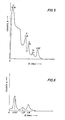
- FIG. 6 shows an example of a coincidence energy spectrum of the gamma rays detected, in one detector, in coincidence with gamma rays detected by the other detector.
- the coincidence spectrum shows a first energy peak at 0.511 Mev, a second energy peak at 1.78 Mev, and a third energy peak at 1.27 Mev.
- the second energy peak (1.78 Mev) corresponds to an energy which is the sum of the energies of first peak (0.511 Mev) and third peak (1.27 Mev).
- Said second energy peak corresponds to the sum of the energy of said first and third energy peaks.
- FIG. 5 represents an energy spectrum, for one detector, of the non coincident events, i.e. the events which are not simultaneous with the events detected in the other detector.
- the spectrum shown comprises the usual energy peaks corresponding to the natural radioactive constituents of the earth formations, i.e. 0.35 Mev and 1.76 Mev peaks representative of the uranium, a 1.46 Mev peak representative of the potassium, and a 2.1 and 2.62 Mev peaks representative of the thorium.
- each detector to wit a coincident spectrum and a non coincident spectrum.
- Coincident and non coincident spectra are respectively directed, by memory/plotter 17, to recorder 11, through respective line I and line II shown on FIG. 1.
- Each of the pulse height analyzers 102, 202 includes a memory (non coincident) and a second (coincident).
- data from a given detector is directed to said first memory of the corresponding pulse height analyzer, for establishing a non coincident spectrum.
- the coincident circuit 20 directs data to said second memory for the purpose of establishing said coincident spectrum.
- the coincident circuit 20 acts as a time coincident gate.
- the ancillary source may be designed to have a very low activity, a few nanoCurie for example. This low activity is of great importance since it allows the ancillary source (i) not to interfere with the measurements, and (ii) to be exempted from most of the stringent regulations related to nuclear sources, in addition to the fact that it is cheap.
- the energy spectrum may be subject to two kinds of deformation. Firstly, the energy spectrum may be uniformly shifted or translated, so that the spectrum energy scale does not pass through the origin. This shift is usually called “offset”, and the corresponding correction is hereafter referred to as “offset correction”. Secondly, the spectrum energy scale may be stretched so that its shape changes; in other words, the corresponding shift is not the same along the spectrum energy scale. The correction step for this shift change is hereafter referred to as "gain stabilization".
- the gain stabilization is based on a reference peak, in this case, said first peak at 0.511 Mev, and may be carried out in any of the usual manner, such as e.g. the one described in U.S. Pat. No. 3,922,541, especially on the Figure 4 and the corresponding description of said patent, which is hereto incorporated herein by reference, or such as one of the methods described in pages 670-672 of the book from Knoll (already referred to) under the paragraph entitled "Spectrum stabilization".
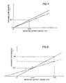
- the gain stabilization may be carried out in the following way, described further in relation with FIG. 7 where the plain line represents the theoretical linear response of a detector and the dotted line is a representation of the actual response of said detector, corresponding to the shifted spectrum.
- the centroid of the 0.511 Mev reference peak is assigned to a given reference channel (or count), e.g. No 55.1.
- the actual centroid of the reference peak is calculated regularly, e.g. every one minute, and in case said actual centroid does not fit the reference channel (or count), the peak is moved (through gain adjustment) to match said reference channel. During this calculation, it is assumed the spectrum is not subject to any offset.
- the resulting drift of the spectrum light be represented by a rotation (about the origin O) of the straight line (non shifted spectrum), which gives the dotted line (shifted spectrum).
- This calculation is made by software methods, known by the one skilled in the art, and by devices shows in FIG. 1, where the output of said gain control unit 19 is connected to the input of the modulator 21 furnishing, at its output, a voltage which is a given function of the voltage applied to its input.
- the modulator 21 is connected to the high-voltage control unit 23 which sends a signal to the high voltage power supply (not shown) in the sonde 10 to appropriately adjust this high voltage and thus the gain of the detectors.
- the method and apparatus of the invention allow one to calibrate (for offset correction) the energy spectrum curve.
- the calibrating step is carried out periodically, with a period sensibly longer (e.g. every ten minutes) than the period of the stabilizing step.
- two reference energy peaks are used, to wit the 0.511 Mev and 1.78 Mev peaks.
- the linear response of the detector on FIG. 8 thus goes from the plain line (non offsetted spectrum) to the dotted line (offsetted spectrum) by a rotation about the point A which abscissa is 0.511 Mev on the plain line of FIG. 8.
- the point A remains fixed since its abscissa 0.511 Mev has been assigned, during the hereinabove described stabilizing step, a given ordinate, i.e. a given channel.
- a particular relationship is calculated between the two channel (count) values corresponding to the respective reference 0.511 Mev and 1.78 Mev peaks, and is compared to a reference relationship value, through offset control 25, and an error signal is generated and fed into the appropriate control circuit of the detectors, inside the tool 10.
- Said relationship is e.g.: (channel of 0.511 Mev) x 1.274 / (channel of 1.78 Mev - channel of 0.511 Mev).
- a third reference peak the one at 1.27 Mev, may be used in combination with the first and second peaks (0.511 Mev and 1.78 Mev). This brings more accuracy to the offset correction, since three points (i.e. 0.511, 1.27 Mev, and 1.78 Mev), instead of two, are thus provided for determining the optimal response curve.
Landscapes
- Physics & Mathematics (AREA)
- High Energy & Nuclear Physics (AREA)
- Life Sciences & Earth Sciences (AREA)
- General Physics & Mathematics (AREA)
- General Life Sciences & Earth Sciences (AREA)
- Geophysics (AREA)
- Spectroscopy & Molecular Physics (AREA)
- Environmental & Geological Engineering (AREA)
- Geology (AREA)
- Health & Medical Sciences (AREA)
- Molecular Biology (AREA)
- Measurement Of Radiation (AREA)
- Geophysics And Detection Of Objects (AREA)
- Spectrometry And Color Measurement (AREA)
- Analysing Materials By The Use Of Radiation (AREA)
Applications Claiming Priority (2)
| Application Number | Priority Date | Filing Date | Title |
|---|---|---|---|
| US400847 | 1989-08-30 | ||
| US07/400,847 US5023449A (en) | 1989-08-30 | 1989-08-30 | Nuclear spectroscopy signal stabilization and calibration method and apparatus |
Publications (2)
| Publication Number | Publication Date |
|---|---|
| EP0416970A2 true EP0416970A2 (de) | 1991-03-13 |
| EP0416970A3 EP0416970A3 (en) | 1993-07-14 |
Family
ID=23585272
Family Applications (1)
| Application Number | Title | Priority Date | Filing Date |
|---|---|---|---|
| EP19900402278 Withdrawn EP0416970A3 (en) | 1989-08-30 | 1990-08-09 | Nuclear spectroscopy signal stabilization and calibration method and apparatus |
Country Status (6)
| Country | Link |
|---|---|
| US (1) | US5023449A (de) |
| EP (1) | EP0416970A3 (de) |
| JP (1) | JP2942603B2 (de) |
| AU (1) | AU627351B2 (de) |
| IE (1) | IE903132A1 (de) |
| NO (1) | NO301305B1 (de) |
Cited By (11)
| Publication number | Priority date | Publication date | Assignee | Title |
|---|---|---|---|---|
| EP0640848A1 (de) * | 1993-08-27 | 1995-03-01 | Halliburton Logging Services, Inc. | Gamma Strahlungsspektroskopie in verrohrten Bohrlöchern |
| US5406078A (en) * | 1992-05-28 | 1995-04-11 | Halliburton Logging Services, Inc. | Induced gamma ray spectorscopy well logging system |
| GB2463707A (en) * | 2008-09-23 | 2010-03-24 | Symetrica Ltd | Gamma-ray spectrometry |
| CN101443679B (zh) * | 2006-05-26 | 2012-05-23 | 塞莫尼根分析技术有限责任公司 | 中子和γ射线监测器 |
| CN103076622A (zh) * | 2012-10-31 | 2013-05-01 | 成都理工大学 | 一种稳谱用随机信号的产生方法 |
| WO2014023954A1 (en) * | 2012-08-10 | 2014-02-13 | Symetrica Limited | Gamma-ray spectrometer |
| EP2877879A1 (de) * | 2012-07-27 | 2015-06-03 | Symetrica Limited | Gammastrahlenspektrometer |
| EP2783246A4 (de) * | 2011-11-24 | 2015-06-24 | Services Petroliers Schlumberger | Verfahren und vorrichtung zur verstärkungsregelung bei einem gammastrahlendetektor |
| GB2579223A (en) * | 2018-11-26 | 2020-06-17 | Bae Systems Plc | Scintillation detector |
| US11415532B2 (en) | 2018-02-15 | 2022-08-16 | Bae Systems Plc | Radiation detector |
| US11650338B2 (en) | 2018-11-23 | 2023-05-16 | Bae Systems Plc | Scintillation detector |
Families Citing this family (33)
| Publication number | Priority date | Publication date | Assignee | Title |
|---|---|---|---|---|
| US5120955A (en) * | 1991-06-06 | 1992-06-09 | Schlumberger Technology Corporation | Logging method and apparatus for correcting natural gamma ray measurements for borehole fluid effects by calculating a borehole correction factor and applying the correction factor to calculated elemental yields |
| US5171986A (en) * | 1991-09-27 | 1992-12-15 | Schlumberger Technology Corporation | Methods and apparatus for calibration of BGO scintillator gamma ray energy spectra |
| US5331553A (en) * | 1992-04-15 | 1994-07-19 | Ugm Medical Systems, Inc. | Three dimensional image reconstruction for a positron emission tomograph |
| US5475727A (en) * | 1993-07-09 | 1995-12-12 | Halliburton Company | Intelligent automatic gain stabilization for radiation detection instrument |
| US5408097A (en) * | 1993-11-29 | 1995-04-18 | Schlumberger Technology Corporation | Method and apparatus for correcting natural gamma ray measurements for borehole fluid effects |
| US5550377A (en) * | 1994-09-20 | 1996-08-27 | Picker International, Inc. | Technique for balancing anger cameras using an externally irradiated crystal and single tube data |
| US5648268A (en) * | 1994-12-06 | 1997-07-15 | Ibm Corporation | Radionuclide exchange detection of ultra trace ionic impurities in water |
| US20030036700A1 (en) * | 2001-07-20 | 2003-02-20 | Weinberg Irving N. | Internal/external coincident gamma camera system |
| US7309857B2 (en) * | 2003-04-10 | 2007-12-18 | North Carolina State University | Gamma ray detectors having improved signal-to-noise ratio and related systems and methods for analyzing materials in an oil well |
| EP2002289A4 (de) * | 2005-02-17 | 2012-05-09 | Triumf Operating As A Joint Venture By The Governors Of The University Of Alberta The University Of | Geographische tomographie mittels kosmischer strahlen |
| US7800052B2 (en) * | 2006-11-30 | 2010-09-21 | Schlumberger Technology Corporation | Method and system for stabilizing gain of a photomultipler used with a radiation detector |
| US7544928B2 (en) * | 2007-10-17 | 2009-06-09 | Baker Hughes Incorporated | High resolution gamma measurements and imaging |
| GB0809198D0 (en) * | 2008-05-21 | 2008-06-25 | Farnsworth Ag | A novel auto calibration technique for radiation detectors |
| FR2933498B1 (fr) * | 2008-07-04 | 2012-07-06 | Smiths Heimann Sas | Procede et dispositif pour detecter la presence, dans une charge, d'objets suspects constitues de materiaux nucleaires de poids atomiques eleve |
| US8546749B2 (en) * | 2008-11-10 | 2013-10-01 | Schlumberger Technology Corporation | Intrinsic radioactivity in a scintillator as count rate reference |
| US8536517B2 (en) * | 2008-11-10 | 2013-09-17 | Schlumberger Technology Corporation | Scintillator based radiation detection |
| US8173953B2 (en) * | 2008-11-10 | 2012-05-08 | Schlumberger Technology Corporation | Gain stabilization of gamma-ray scintillation detector |
| US20100128852A1 (en) * | 2008-11-24 | 2010-05-27 | Veritainer Corporation | Detector Characterization and Calibration |
| US8865011B2 (en) | 2009-05-20 | 2014-10-21 | Schlumberger Technology Corporation | Method for optimizing the spectral performance of scintillator crystals |
| EP2596386A4 (de) | 2010-08-26 | 2017-09-13 | Smith International, Inc. | Verfahren zur messung der dichte einer unterirdischen formation mit einem neutronengenerator |
| JP5450356B2 (ja) * | 2010-11-12 | 2014-03-26 | 株式会社日立製作所 | 放射線検出方法 |
| US9091772B2 (en) * | 2012-09-14 | 2015-07-28 | Thermo Fisher Scientific Inc. | Scintillation detector gain control |
| US9658351B2 (en) | 2012-10-05 | 2017-05-23 | Schlumberger Technology Corporation | Null space projection for sourceless gain stabilization in downhole gamma ray spectroscopy |
| BR112016007452A2 (pt) | 2013-11-06 | 2017-08-01 | Halliburton Energy Services Inc | sistema para medir raios gama naturais, método para detectar radiação gama natural, e, aparatos |
| US9360570B2 (en) * | 2014-04-18 | 2016-06-07 | Siemens Medical Solutions Usa, Inc. | Method and apparatus for automatic calibration check of PET scanner using intrinsic background radiation of scintillator crystals |
| JP2016180625A (ja) * | 2015-03-23 | 2016-10-13 | 株式会社東芝 | 放射線検出装置、入出力較正方法、及び入出力較正プログラム |
| WO2016153518A1 (en) | 2015-03-26 | 2016-09-29 | Halliburton Energy Services, Inc. | Gamma-ray spectrometer calibration systems and methods |
| WO2019099017A1 (en) | 2017-11-17 | 2019-05-23 | Halliburton Energy Services, Inc. | Calibrating wellbore spectrometers |
| CN108318910B (zh) * | 2018-01-25 | 2019-07-26 | 核工业航测遥感中心 | 基于7Be峰的航空伽玛能谱仪稳谱方法 |
| RU2722863C1 (ru) * | 2018-04-05 | 2020-06-04 | Общество с ограниченной ответственностью "Научно-производственное предприятие ЭНЕРГИЯ" | Способ стабилизации энергетической шкалы при определении объемной плотности и эффективного атомного номера горных пород методом ггк-лп |
| US11163089B2 (en) * | 2019-07-26 | 2021-11-02 | Schlumberger Technology Corporation | Neutron imaging devices for cased wells and open boreholes |
| CN113625333B (zh) * | 2021-07-12 | 2023-08-29 | 成都理工大学 | 基于纳秒光源的能谱仪多参数测试标定系统及方法 |
| CN118464964B (zh) * | 2024-07-11 | 2024-10-11 | 合肥金星智控科技股份有限公司 | 一种基于中子活化技术的厚度不均匀物料检测方法及装置 |
Family Cites Families (21)
| Publication number | Priority date | Publication date | Assignee | Title |
|---|---|---|---|---|
| FR1077483A (fr) * | 1952-05-28 | 1954-11-08 | Westinghouse Electric Corp | Dispositif à décharges électriques dans une vapeur |
| US2769916A (en) * | 1952-10-02 | 1956-11-06 | Gulf Research Development Co | Coincidence-type slow neutron detector |
| US3101409A (en) * | 1962-05-03 | 1963-08-20 | Lloyd E Fite | Drift control in an analytical gamma ray spectrometer |
| US3562526A (en) * | 1967-10-17 | 1971-02-09 | Phillips Petroleum Co | Neutron-gamma ray well logging apparatus employing spaced gamma ray detectors |
| US3633030A (en) * | 1969-05-12 | 1972-01-04 | Schlumberger Technology Corp | Semiconductor detector borehole logging technique |
| FR2168849B1 (de) * | 1972-01-24 | 1976-09-03 | Schlumberger Prospection | |
| FR2211664B1 (de) * | 1972-12-21 | 1976-08-27 | Schlumberger Prospection | |
| US3935556A (en) * | 1973-07-23 | 1976-01-27 | Halliburton Company | Dual function logging tool and method |
| MX3047E (es) * | 1973-10-01 | 1980-03-04 | Schlumberge Surenco S A Univer | Procedimiento para la produccion de una mezcla de procedimiento y dispositivo mejorado para determinar el contenido de potasio, uranio y torio de una sulfatos basicos e hidratos de aluminio formacion geologica |
| USRE30827E (en) * | 1974-05-22 | 1981-12-22 | Institut Francais Du Petrole | Process and device for the determination of the characteristics of the geological formations traversed by a borehole |
| US3955088A (en) * | 1974-10-02 | 1976-05-04 | G. D. Searle & Co. | Positron imaging device with plural coincidence channels and graded radiation absorption |
| US4053767A (en) * | 1976-08-23 | 1977-10-11 | Halliburton Company | Method and apparatus for stabilizing signals in radioactive well logging tools |
| US4220851A (en) * | 1978-07-03 | 1980-09-02 | Texaco Inc. | Gain stabilization for radioactivity well logging apparatus |
| US4300043A (en) * | 1979-05-29 | 1981-11-10 | Halliburton Company | Stabilized radioactive logging method and apparatus |
| FR2485752A1 (fr) * | 1980-06-25 | 1981-12-31 | Schlumberger Prospection | Procede et dispositif de mesure de rayons gamma dans un sondage |
| US4418282A (en) * | 1981-06-29 | 1983-11-29 | Beckman Instruments, Inc. | Method and apparatus for determining random coincidence count rate in a scintillation counter utilizing the coincidence technique |
| US4450354A (en) * | 1982-07-06 | 1984-05-22 | Halliburton Company | Gain stabilized natural gamma ray detection of casing thickness in a borehole |
| US4580048A (en) * | 1983-08-31 | 1986-04-01 | Mobil Oil Corporation | System for measuring the natural gamma radiation of surface and subsurface formations |
| US4578578A (en) * | 1983-12-05 | 1986-03-25 | Texaco Inc. | Method for correcting spectrum shift |
| US4668863A (en) * | 1985-04-10 | 1987-05-26 | Dresser Industries, Inc. | Neutron logging time spectral data acquisition system and method |
| US4945233A (en) * | 1988-07-25 | 1990-07-31 | Western Atlas International, Inc. | Calibration and quality control system for neutron logging instruments |
-
1989
- 1989-08-30 US US07/400,847 patent/US5023449A/en not_active Expired - Lifetime
-
1990
- 1990-08-09 EP EP19900402278 patent/EP0416970A3/en not_active Withdrawn
- 1990-08-29 IE IE313290A patent/IE903132A1/en unknown
- 1990-08-29 JP JP22790490A patent/JP2942603B2/ja not_active Expired - Lifetime
- 1990-08-29 AU AU61965/90A patent/AU627351B2/en not_active Ceased
- 1990-08-29 NO NO903786A patent/NO301305B1/no not_active IP Right Cessation
Cited By (16)
| Publication number | Priority date | Publication date | Assignee | Title |
|---|---|---|---|---|
| US5406078A (en) * | 1992-05-28 | 1995-04-11 | Halliburton Logging Services, Inc. | Induced gamma ray spectorscopy well logging system |
| EP0640848A1 (de) * | 1993-08-27 | 1995-03-01 | Halliburton Logging Services, Inc. | Gamma Strahlungsspektroskopie in verrohrten Bohrlöchern |
| CN101443679B (zh) * | 2006-05-26 | 2012-05-23 | 塞莫尼根分析技术有限责任公司 | 中子和γ射线监测器 |
| GB2463707A (en) * | 2008-09-23 | 2010-03-24 | Symetrica Ltd | Gamma-ray spectrometry |
| WO2010034962A2 (en) | 2008-09-23 | 2010-04-01 | Symetrica Limited | Gamma-ray spectrometry |
| WO2010034962A3 (en) * | 2008-09-23 | 2010-10-28 | Symetrica Limited | Stabilization in gamma-ray spectometry |
| GB2463707B (en) * | 2008-09-23 | 2011-06-01 | Symetrica Ltd | Gamma-ray spectrometry |
| US8384016B2 (en) | 2008-09-23 | 2013-02-26 | Symetrica Limited | Stabilization in gamma-ray spectometry |
| EP2783246A4 (de) * | 2011-11-24 | 2015-06-24 | Services Petroliers Schlumberger | Verfahren und vorrichtung zur verstärkungsregelung bei einem gammastrahlendetektor |
| EP2877879A1 (de) * | 2012-07-27 | 2015-06-03 | Symetrica Limited | Gammastrahlenspektrometer |
| US9465119B2 (en) | 2012-08-10 | 2016-10-11 | Symetrica Limited | Gamma-ray spectrometer |
| WO2014023954A1 (en) * | 2012-08-10 | 2014-02-13 | Symetrica Limited | Gamma-ray spectrometer |
| CN103076622A (zh) * | 2012-10-31 | 2013-05-01 | 成都理工大学 | 一种稳谱用随机信号的产生方法 |
| US11415532B2 (en) | 2018-02-15 | 2022-08-16 | Bae Systems Plc | Radiation detector |
| US11650338B2 (en) | 2018-11-23 | 2023-05-16 | Bae Systems Plc | Scintillation detector |
| GB2579223A (en) * | 2018-11-26 | 2020-06-17 | Bae Systems Plc | Scintillation detector |
Also Published As
| Publication number | Publication date |
|---|---|
| IE903132A1 (en) | 1991-03-13 |
| AU6196590A (en) | 1991-03-07 |
| NO301305B1 (no) | 1997-10-06 |
| NO903786L (no) | 1991-03-01 |
| EP0416970A3 (en) | 1993-07-14 |
| JPH03150488A (ja) | 1991-06-26 |
| AU627351B2 (en) | 1992-08-20 |
| JP2942603B2 (ja) | 1999-08-30 |
| US5023449A (en) | 1991-06-11 |
| NO903786D0 (no) | 1990-08-29 |
Similar Documents
| Publication | Publication Date | Title |
|---|---|---|
| US5023449A (en) | Nuclear spectroscopy signal stabilization and calibration method and apparatus | |
| US7642507B2 (en) | Apparatus and methods for interlaced density and neutron measurements | |
| US5459314A (en) | Method for correcting density measurements that are affected by natural and neutron-induced gamma radiation | |
| US5600135A (en) | Spectral gain stabilization using gross shape features of largely invariant spectra | |
| US5440118A (en) | Methods and apparatus for determining formation lithology by gamma ray spectroscopy | |
| CA1163379A (en) | Method and apparatus for measuring gamma rays in a borehole | |
| EP0473467B1 (de) | Gammastrahlungsspektroskopieverfahren und Vorrichtung zur Konzentrationsbestimmung von Elementen in einem unbekannten Material | |
| US7081616B2 (en) | Downhole gamma-ray detection | |
| US5180917A (en) | Self-calibrating proportional counter | |
| US4053767A (en) | Method and apparatus for stabilizing signals in radioactive well logging tools | |
| US4529877A (en) | Borehole compensated density logs corrected for naturally occurring gamma rays | |
| GB2422662A (en) | Gain stabilisation of spectral gamma ray measurement systems | |
| US3829686A (en) | Pulsed neutron logging system with gain compensation | |
| EP0206593B1 (de) | Verfahren und Vorrichtung mit Bohrlochkompensation | |
| Hoppie et al. | Natural gamma-ray measurements on ODP cores: Introduction to procedures with examples from Leg 150 | |
| US3336476A (en) | Detecting radioactive potassium in the presence of uranium and thorium | |
| US5120955A (en) | Logging method and apparatus for correcting natural gamma ray measurements for borehole fluid effects by calculating a borehole correction factor and applying the correction factor to calculated elemental yields | |
| US4730263A (en) | Method and device for measuring gamma radiation | |
| US3767921A (en) | Well logging system with linearity control | |
| US5408097A (en) | Method and apparatus for correcting natural gamma ray measurements for borehole fluid effects | |
| US7361886B2 (en) | Corrections of gamma-ray responses | |
| US3156822A (en) | Induced gamma ray logging at a plurality of levels in a well bore | |
| US3988581A (en) | Radioactive well logging system with shale (boron) compensation by gamma ray build-up | |
| US3213279A (en) | Calibration of radioactive well logging system | |
| EP0224351A1 (de) | Vorrichtung zur Bestimmung von gamma-Strahlung in einem Bohrloch |
Legal Events
| Date | Code | Title | Description |
|---|---|---|---|
| PUAI | Public reference made under article 153(3) epc to a published international application that has entered the european phase |
Free format text: ORIGINAL CODE: 0009012 |
|
| AK | Designated contracting states |
Kind code of ref document: A2 Designated state(s): AT DE DK FR GB IT NL |
|
| PUAL | Search report despatched |
Free format text: ORIGINAL CODE: 0009013 |
|
| AK | Designated contracting states |
Kind code of ref document: A3 Designated state(s): AT DE DK FR GB IT NL |
|
| STAA | Information on the status of an ep patent application or granted ep patent |
Free format text: STATUS: THE APPLICATION IS DEEMED TO BE WITHDRAWN |
|
| 18D | Application deemed to be withdrawn |
Effective date: 19940115 |