EP0416974A1 - Flüssigkeitsverteiler mit elektrischer Heizung, insbesondere zur Bereitung von Kaffee - Google Patents
Flüssigkeitsverteiler mit elektrischer Heizung, insbesondere zur Bereitung von Kaffee Download PDFInfo
- Publication number
- EP0416974A1 EP0416974A1 EP90402324A EP90402324A EP0416974A1 EP 0416974 A1 EP0416974 A1 EP 0416974A1 EP 90402324 A EP90402324 A EP 90402324A EP 90402324 A EP90402324 A EP 90402324A EP 0416974 A1 EP0416974 A1 EP 0416974A1
- Authority
- EP
- European Patent Office
- Prior art keywords
- chamber
- reservoir
- liquid
- resistor
- distributor according
- Prior art date
- Legal status (The legal status is an assumption and is not a legal conclusion. Google has not performed a legal analysis and makes no representation as to the accuracy of the status listed.)
- Withdrawn
Links
- 239000007788 liquid Substances 0.000 title claims abstract description 22
- 238000010438 heat treatment Methods 0.000 title description 7
- 239000002184 metal Substances 0.000 claims abstract description 3
- 230000000694 effects Effects 0.000 claims description 4
- 238000005868 electrolysis reaction Methods 0.000 claims description 3
- 238000009413 insulation Methods 0.000 claims description 3
- 235000012171 hot beverage Nutrition 0.000 abstract description 2
- 238000002360 preparation method Methods 0.000 abstract description 2
- 239000011810 insulating material Substances 0.000 abstract 1
- XLYOFNOQVPJJNP-UHFFFAOYSA-N water Substances O XLYOFNOQVPJJNP-UHFFFAOYSA-N 0.000 description 12
- 230000007797 corrosion Effects 0.000 description 3
- 238000005260 corrosion Methods 0.000 description 3
- 238000007789 sealing Methods 0.000 description 3
- 238000010586 diagram Methods 0.000 description 2
- 230000002093 peripheral effect Effects 0.000 description 2
- 239000004033 plastic Substances 0.000 description 2
- 229910001220 stainless steel Inorganic materials 0.000 description 2
- 239000010935 stainless steel Substances 0.000 description 2
- 239000004743 Polypropylene Substances 0.000 description 1
- 240000008042 Zea mays Species 0.000 description 1
- 235000005824 Zea mays ssp. parviglumis Nutrition 0.000 description 1
- 235000002017 Zea mays subsp mays Nutrition 0.000 description 1
- 230000000712 assembly Effects 0.000 description 1
- 238000000429 assembly Methods 0.000 description 1
- 230000000903 blocking effect Effects 0.000 description 1
- 235000005822 corn Nutrition 0.000 description 1
- 238000009434 installation Methods 0.000 description 1
- 238000004519 manufacturing process Methods 0.000 description 1
- 239000000463 material Substances 0.000 description 1
- 238000005192 partition Methods 0.000 description 1
- -1 polypropylene Polymers 0.000 description 1
- 229920001155 polypropylene Polymers 0.000 description 1
- 239000000843 powder Substances 0.000 description 1
- 230000001681 protective effect Effects 0.000 description 1
- 230000000717 retained effect Effects 0.000 description 1
- 239000000725 suspension Substances 0.000 description 1
Images
Classifications
-
- A—HUMAN NECESSITIES
- A47—FURNITURE; DOMESTIC ARTICLES OR APPLIANCES; COFFEE MILLS; SPICE MILLS; SUCTION CLEANERS IN GENERAL
- A47J—KITCHEN EQUIPMENT; COFFEE MILLS; SPICE MILLS; APPARATUS FOR MAKING BEVERAGES
- A47J31/00—Apparatus for making beverages
-
- A—HUMAN NECESSITIES
- A47—FURNITURE; DOMESTIC ARTICLES OR APPLIANCES; COFFEE MILLS; SPICE MILLS; SUCTION CLEANERS IN GENERAL
- A47J—KITCHEN EQUIPMENT; COFFEE MILLS; SPICE MILLS; APPARATUS FOR MAKING BEVERAGES
- A47J31/00—Apparatus for making beverages
- A47J31/44—Parts or details or accessories of beverage-making apparatus
- A47J31/54—Water boiling vessels in beverage making machines
-
- B—PERFORMING OPERATIONS; TRANSPORTING
- B60—VEHICLES IN GENERAL
- B60N—SEATS SPECIALLY ADAPTED FOR VEHICLES; VEHICLE PASSENGER ACCOMMODATION NOT OTHERWISE PROVIDED FOR
- B60N3/00—Arrangements or adaptations of other passenger fittings, not otherwise provided for
- B60N3/16—Arrangements or adaptations of other passenger fittings, not otherwise provided for of cooking or boiling devices
Definitions
- the invention essentially relates to an electrically heated liquid distributor in which the liquid contained in a tank is heated by an electrical resistance disposed at the base of a substantially vertical duct terminated by a curved spout through which it flows under the action of pressure.
- the dispenser object of the invention operates according to the principle of household coffee makers in which the liquid contained in a tank is heated to supply a filter containing a coffee powder.
- the known devices heat all of the water contained in the tank, they are supplied by the electrical sector and have a relatively high inertia.
- the invention relates particularly to an apparatus designed for the preparation of hot drinks in a vehicle, car, truck, caravan, boat, plane, etc ...; for this purpose, it is designed so as to be compact and to consume very little energy, this generally coming from the vehicle battery.
- the dispenser object of the invention is characterized in that the electrical resistance is enclosed in a chamber connected to the base of the conduit and supplied by the reservoir through a valve preventing the ascent of liquid to said reservoir when the resistance heats the liquid in said chamber, said electrical resistance consisting of a metal wire, such as stainless steel or the like, not coated with insulation and supplied with low voltage.
- the metallic wire of the resistor is wound in a spiral, the extreme turns of which are connected to two supply terminals, the latter being each extended by a pole horn made of wire with a diameter greater than that of the turns, said horns extending substantially perpendicular to the axis of the spiral.
- the electrical circuit for supplying the resistor comprises a switch with which means are associated preventing the closing of said switch in the event of a lack of liquid in the tank.
- Said means preventing the closing of the switch comprise a detector for the presence of liquid in the reservoir associated with a transistor which controls a relay for actuating the switch.
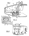
- the distributor 10 is in the form of a housing made for example of plastic material, comprising a cover 12 provided with an opening 14 connected to a bottom 16, the cover 12 and the bottom 16 being connected by side walls and by a partition substantially vertical 18.
- a tank forming tank 20 intended to receive the liquid to be dispensed which is introduced through the opening 14.
- the tank forming tank 20 has a bottom wall 22 in which are provided two orifices: on the one hand an orifice 24 giving access to a well 26 opening at its lower part in a conduit 28 connected to a chamber 30 which is in the form of a cylinder of hollow circular section with horizontal axis and on the other hand an orifice 32 through which passes a tubing 34 disposed at the upper part of the chamber 30 to which is connected a vertical pipe or tube 36, a sealing tip 38 ensuring the sealing between the tubing 34, the lower part of the pipe 36 and the bottom 22 of the tank.
- the conduit 36 is extended by a bent portion 38 and ends with a pouring spout 40 which is at a level higher than the maximum level of the water in the tank.
- the parts 26, 28; 30 assemblies will preferably have the general shape of a pipe comprising, as a hearth, the chamber 30 with its exhaust chimney 34 in the upper part and, opening out laterally, the conduit 28 forming "pipe pipe", normally slightly inclined relative to the horizontal, descending towards the hearth 30 from its side where the float retaining well 26 opens, the volume of which is comparable to that of the chamber 30.
- valve 42 comprising an annular flange 44 capable of coming to cooperate with the lower part of the bottom 22 when the reservoir 20 and the chamber 30 are filled with water, said valve 42 having a density lower than that of water.
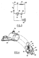
- FIG. 1 shows schematically the electrical heating resistance of the distributor 46 which is in the form of a spiral of wires, made of stainless steel or the like, not coated with insulation, and we have shown at 48 and 50 the resistor supply terminals 46.
- FIG. 4 shows in perspective the plug 53 for supplying the resistor 46 constituted by a spiral extending along an axis perpendicular to said plug which cooperates tightly with the chamber 30 forming a boiler.
- the spiral 46 extends axially between two pole horns 49, 51 to which it is connected by its extreme turns, these horns forming electrodes making it possible to move the electrolysis zone which, in the absence of such horns , would be located at the resistor 46, between the turns of the latter.
- the pole horns in question extend in planes substantially perpendicular to the axis of the spiral and in this case each extend slightly beyond the spiral-horn junction point.
- these same horns are connected to two pads 55, 57, to which the two terminals 48, 50 for connecting the resistor are electrically connected, through the plug.
- sealing means are provided.
- the polar horns are produced in a wire slightly larger than the wire of the spiral. They have for example a diameter of 0.8 mm for a section of the wire of the spiral of 0.6 mm, the connection pads 55, 57 then having a diameter of approximately 4 mm.
- the resistor 46 can be supplied by a battery connected to terminals 60 and 62 with the interposition of a switch 64.
- the switch 64 is controlled by a relay of the electromagnetic type 66 which causes it to close when it is excited by closing a circuit comprising the level detector 52, a transistor 68, a diode 70 and a general switch for controlling the distributor 72 of the push button type.
- the level detector 52 may be of the type comprising two electrodes which, when immersed in water, close the circuit comprising the transistor, the relay 66 and the diode 70 which is a biasing diode, a protective diode 74 of the switch 13 being provided at the terminals of the relay 66.
- the valve 42 During filling of the reservoir 20 with water, the valve 42 remains at the bottom of the well 26 until the chamber 30 has been filled with water. It will be noted that the capacity of the chamber is reduced, its volume being very much lower than that of the cup, for example in a ratio of approximately 1 to 5, a tenfold ratio being able to be retained between the volume of chamber 30 and that of the reservoir. 20.
- the resistor 46 heats the water contained therein and presses the valve 42 against the seat formed by the lower edge of the orifice 24 , this thanks to the annular flange 44.
- the expanding water in the chamber 30 and the conduit 36 is ejected by the pouring spout 40 towards the cup disposed directly above the latter.
- the valve 42 falls towards the bottom of the well 26 and ensures the water supply to the chamber 30. If the push button 72 is kept closed, a new heating operation occurs and it is possible to fill the cup located below the spout 40 until it is partially or completely filled.
- FIG. 2 shows a perspective view of a dispenser according to the invention.
- the cup and the reference 82 a cover coming to be placed above the opening 14 for filling the reservoir 20.
- the push button 72 Also shown in this figure is the push button 72.
- a stirrup 84 whose vertical tabs enclose the distributor which is hinged on said stirrup with the possibility of blocking by means of knurled head nuts 86, such a suspension arrangement allowing the installation of the distributor in a vehicle.
- FIG. 5 it illustrates an alternative embodiment of the valve 42 of Figure 1.
- This floating valve marked 90 is formed in one piece of plastic such as polypropylene. It is shaped to be housed in the well 26 of the apparatus and comprises a central cylindrical body 91 of circular section surmounted in its vertical cylinder axis by a first cross 92, with four branches, of smaller section suitable for engaging through the orifice 24 in the high closed position of the valve to guide the latter there; a peripheral shoulder 93 then coming to cooperate with a rim forming a seat 94 of the orifice 24.
- plastic such as polypropylene
- the body 91 is extended by a double cross 95, 96 stepped so that the lower cross 96 of smaller section guides the valve in the orifice 27 formed in the lower part of the chamber 26 for communication with the conduit 28, a peripheral shoulder 97 formed at the location of the connection with change of cross section 95, 96 cooperating with the edge 27a (forming a low seat for the valve) of the orifice 27.
Landscapes
- Engineering & Computer Science (AREA)
- Food Science & Technology (AREA)
- Transportation (AREA)
- Mechanical Engineering (AREA)
- Instantaneous Water Boilers, Portable Hot-Water Supply Apparatuses, And Control Of Portable Hot-Water Supply Apparatuses (AREA)
- Resistance Heating (AREA)
- Cookers (AREA)
Applications Claiming Priority (2)
| Application Number | Priority Date | Filing Date | Title |
|---|---|---|---|
| FR8911218A FR2651109A1 (fr) | 1989-08-24 | 1989-08-24 | Distributeur de liquide a chauffage electrique en particulier pour la preparation du cafe. |
| FR8911218 | 1989-08-24 |
Publications (1)
| Publication Number | Publication Date |
|---|---|
| EP0416974A1 true EP0416974A1 (de) | 1991-03-13 |
Family
ID=9384900
Family Applications (1)
| Application Number | Title | Priority Date | Filing Date |
|---|---|---|---|
| EP90402324A Withdrawn EP0416974A1 (de) | 1989-08-24 | 1990-08-21 | Flüssigkeitsverteiler mit elektrischer Heizung, insbesondere zur Bereitung von Kaffee |
Country Status (4)
| Country | Link |
|---|---|
| EP (1) | EP0416974A1 (de) |
| JP (1) | JPH03176011A (de) |
| CA (1) | CA2023725A1 (de) |
| FR (1) | FR2651109A1 (de) |
Cited By (5)
| Publication number | Priority date | Publication date | Assignee | Title |
|---|---|---|---|---|
| FR2738006A1 (fr) * | 1995-08-22 | 1997-02-28 | Beau Eric | Distributeur de liquide chaud ou froid |
| WO1998031266A1 (en) * | 1997-01-16 | 1998-07-23 | Mars U.K. Limited | Water heater |
| WO1998033674A1 (fr) * | 1997-01-31 | 1998-08-06 | Evan Societe Anonyme | Chauffe-eau electronique embarque sur vehicule automobile |
| WO2001072187A1 (fr) | 2000-03-28 | 2001-10-04 | Michel Vannoye | Appareil compact distributeur d'eau chaude pour boisson chaude |
| WO2017097653A1 (en) * | 2015-12-11 | 2017-06-15 | Arcelik Anonim Sirketi | A coffee machine comprising an external water tank |
Families Citing this family (1)
| Publication number | Priority date | Publication date | Assignee | Title |
|---|---|---|---|---|
| NZ596112A (en) * | 2009-05-14 | 2012-12-21 | Cosmos Solar Pty Ltd | Method of heating fluids by supplying an element with a high voltage then transforming to a low voltage |
Citations (4)
| Publication number | Priority date | Publication date | Assignee | Title |
|---|---|---|---|---|
| BE524326A (de) * | ||||
| US2926234A (en) * | 1958-02-13 | 1960-02-23 | Westinghouse Electric Corp | Appliance |
| FR2105400A5 (de) * | 1970-09-04 | 1972-04-28 | Debreczeny Georges | |
| DE3532058A1 (de) * | 1985-09-09 | 1987-03-12 | Elektro Grosshandlung Theodor | Heisswasserboiler fuer omnibusse |
-
1989
- 1989-08-24 FR FR8911218A patent/FR2651109A1/fr not_active Withdrawn
-
1990
- 1990-08-21 EP EP90402324A patent/EP0416974A1/de not_active Withdrawn
- 1990-08-21 CA CA 2023725 patent/CA2023725A1/fr not_active Abandoned
- 1990-08-24 JP JP22144390A patent/JPH03176011A/ja active Pending
Patent Citations (4)
| Publication number | Priority date | Publication date | Assignee | Title |
|---|---|---|---|---|
| BE524326A (de) * | ||||
| US2926234A (en) * | 1958-02-13 | 1960-02-23 | Westinghouse Electric Corp | Appliance |
| FR2105400A5 (de) * | 1970-09-04 | 1972-04-28 | Debreczeny Georges | |
| DE3532058A1 (de) * | 1985-09-09 | 1987-03-12 | Elektro Grosshandlung Theodor | Heisswasserboiler fuer omnibusse |
Cited By (7)
| Publication number | Priority date | Publication date | Assignee | Title |
|---|---|---|---|---|
| FR2738006A1 (fr) * | 1995-08-22 | 1997-02-28 | Beau Eric | Distributeur de liquide chaud ou froid |
| WO1998031266A1 (en) * | 1997-01-16 | 1998-07-23 | Mars U.K. Limited | Water heater |
| WO1998033674A1 (fr) * | 1997-01-31 | 1998-08-06 | Evan Societe Anonyme | Chauffe-eau electronique embarque sur vehicule automobile |
| FR2759154A1 (fr) * | 1997-01-31 | 1998-08-07 | Evan | Chauffe-eau electronique embarque sur vehicule automobile |
| WO2001072187A1 (fr) | 2000-03-28 | 2001-10-04 | Michel Vannoye | Appareil compact distributeur d'eau chaude pour boisson chaude |
| FR2806896A1 (fr) | 2000-03-28 | 2001-10-05 | Michel Vannoye | Appareil compact distributeur d'eau chaude pour boisson chaude |
| WO2017097653A1 (en) * | 2015-12-11 | 2017-06-15 | Arcelik Anonim Sirketi | A coffee machine comprising an external water tank |
Also Published As
| Publication number | Publication date |
|---|---|
| FR2651109A1 (fr) | 1991-03-01 |
| CA2023725A1 (fr) | 1991-02-25 |
| JPH03176011A (ja) | 1991-07-31 |
Similar Documents
| Publication | Publication Date | Title |
|---|---|---|
| EP0240387B1 (de) | Verfahren und Vorrichtung zur raschen Verdampfung einer Flüssigkeit | |
| EP0088253B1 (de) | Vorrichtung zur Beschickung eines Schachtofens | |
| FR2594708A1 (fr) | Dispositif de filtrage de carburant du type a chauffage du carburant | |
| FR2855079A1 (fr) | Corps de buse pour installation de nettoyage equipant un vehicule automobile | |
| CA2023725A1 (fr) | Distributeur de liquide a chauffage electrique en particulier pour la preparation du cafe | |
| FR2768970A1 (fr) | Tube de remplissage pour reservoir de carburant d'un vehicule | |
| EP0388270A1 (de) | Spender für zähflüssige Substanzen | |
| EP1110789B1 (de) | Kraftstofftankventil und damit ausgerüsteter Tank | |
| EP1151218B1 (de) | Aseptisches durchflussregulierventil mit einer koaxialen wicklung für mehrere durchflussraten und füllvorrichtung mit einem solchen ventil | |
| FR2485636A1 (fr) | Perfectionnements apportes aux carburateurs auxiliaires de demarrage pour moteurs a combustion interne | |
| MC788A1 (fr) | Pistolet pour le lavage de surfaces telles que vitres, glaces, etc.... | |
| FR2583141A1 (fr) | Generateur de vapeur a resistance electrique pour appareil electromenager | |
| FR2597595A3 (fr) | Dispositif pour detecter le niveau d'un liquide dans un reservoir | |
| EP0286481B1 (de) | Verfahren und Vorrichtung zum Befestigen eines Metallklotzes auf einer Oberfläche einer ophthalmischen Linse durch Aufformen von geschmolzenem Metall | |
| EP1556538A1 (de) | Bügeleisen mit einem von dessen rückseite aus befüllbaren wasserspeicher | |
| EP0175653A2 (de) | Heizvorrichtung für Brennstoffilter | |
| FR2494464A1 (fr) | Dispositif pour le remplissage d'un reservoir de chasse d'eau | |
| FR2669209A1 (fr) | Entonnoir pour le chargement du sel dans une machine a laver la vaisselle. | |
| EP0678267B1 (de) | Heisswasserbereiter für "Espresso"-Kaffeemaschinen | |
| FR2703836A3 (fr) | Dispositif de flotteur amélioré pour vérifier le niveau d'eau distillée dans les batteries électriques. | |
| FR2761445A1 (fr) | Dispositif de distribution pour liquides | |
| FR2740794A1 (fr) | Mecanisme de chasse d'eau | |
| CA2849687A1 (fr) | Appareil de repassage comportant un dispositif de traitement de l'eau | |
| FR2473971A1 (fr) | Reservoir de liquide de freinage pour vehicules automobiles | |
| FR2744615A3 (fr) | Bouilloire electrique amelioree |
Legal Events
| Date | Code | Title | Description |
|---|---|---|---|
| PUAI | Public reference made under article 153(3) epc to a published international application that has entered the european phase |
Free format text: ORIGINAL CODE: 0009012 |
|
| AK | Designated contracting states |
Kind code of ref document: A1 Designated state(s): AT BE CH DE DK ES GB GR IT LI LU NL SE |
|
| 17P | Request for examination filed |
Effective date: 19910823 |
|
| STAA | Information on the status of an ep patent application or granted ep patent |
Free format text: STATUS: THE APPLICATION IS DEEMED TO BE WITHDRAWN |
|
| 18D | Application deemed to be withdrawn |
Effective date: 19930301 |