EP0417005B1 - System zum Spritzgiessen eines geschmolzenen Materials in eine Aufnahmevorrichtung wie eine Form - Google Patents
System zum Spritzgiessen eines geschmolzenen Materials in eine Aufnahmevorrichtung wie eine Form Download PDFInfo
- Publication number
- EP0417005B1 EP0417005B1 EP90402452A EP90402452A EP0417005B1 EP 0417005 B1 EP0417005 B1 EP 0417005B1 EP 90402452 A EP90402452 A EP 90402452A EP 90402452 A EP90402452 A EP 90402452A EP 0417005 B1 EP0417005 B1 EP 0417005B1
- Authority
- EP
- European Patent Office
- Prior art keywords
- injection
- molten material
- chamber
- injection chamber
- melting
- Prior art date
- Legal status (The legal status is an assumption and is not a legal conclusion. Google has not performed a legal analysis and makes no representation as to the accuracy of the status listed.)
- Expired - Lifetime
Links
- 239000012768 molten material Substances 0.000 title claims abstract description 37
- 238000001746 injection moulding Methods 0.000 title claims 2
- 238000002347 injection Methods 0.000 claims abstract description 56
- 239000007924 injection Substances 0.000 claims abstract description 56
- 238000002844 melting Methods 0.000 claims abstract description 25
- 230000008018 melting Effects 0.000 claims abstract description 25
- 239000000463 material Substances 0.000 claims description 17
- 239000012530 fluid Substances 0.000 claims description 12
- 238000007789 sealing Methods 0.000 claims description 6
- 238000004891 communication Methods 0.000 claims description 4
- 238000009413 insulation Methods 0.000 claims description 3
- 239000000155 melt Substances 0.000 claims description 3
- 238000007599 discharging Methods 0.000 claims description 2
- 239000007787 solid Substances 0.000 claims description 2
- 210000003414 extremity Anatomy 0.000 claims 4
- 230000001960 triggered effect Effects 0.000 claims 2
- 210000001364 upper extremity Anatomy 0.000 claims 1
- 239000008187 granular material Substances 0.000 description 4
- 238000010438 heat treatment Methods 0.000 description 4
- 239000000919 ceramic Substances 0.000 description 3
- 230000000694 effects Effects 0.000 description 2
- 230000003647 oxidation Effects 0.000 description 2
- 238000007254 oxidation reaction Methods 0.000 description 2
- 229910000906 Bronze Inorganic materials 0.000 description 1
- 239000000853 adhesive Substances 0.000 description 1
- 230000001070 adhesive effect Effects 0.000 description 1
- 239000010974 bronze Substances 0.000 description 1
- 238000001816 cooling Methods 0.000 description 1
- KUNSUQLRTQLHQQ-UHFFFAOYSA-N copper tin Chemical compound [Cu].[Sn] KUNSUQLRTQLHQQ-UHFFFAOYSA-N 0.000 description 1
- 230000001419 dependent effect Effects 0.000 description 1
- 230000004927 fusion Effects 0.000 description 1
- 239000003292 glue Substances 0.000 description 1
- 238000012986 modification Methods 0.000 description 1
- 230000004048 modification Effects 0.000 description 1
- 238000000465 moulding Methods 0.000 description 1
- 239000008188 pellet Substances 0.000 description 1
- 229920000642 polymer Polymers 0.000 description 1
- 239000011148 porous material Substances 0.000 description 1
- 230000005855 radiation Effects 0.000 description 1
Images

Classifications
-
- B—PERFORMING OPERATIONS; TRANSPORTING
- B29—WORKING OF PLASTICS; WORKING OF SUBSTANCES IN A PLASTIC STATE IN GENERAL
- B29C—SHAPING OR JOINING OF PLASTICS; SHAPING OF MATERIAL IN A PLASTIC STATE, NOT OTHERWISE PROVIDED FOR; AFTER-TREATMENT OF THE SHAPED PRODUCTS, e.g. REPAIRING
- B29C45/00—Injection moulding, i.e. forcing the required volume of moulding material through a nozzle into a closed mould; Apparatus therefor
- B29C45/17—Component parts, details or accessories; Auxiliary operations
- B29C45/46—Means for plasticising or homogenising the moulding material or forcing it into the mould
-
- B—PERFORMING OPERATIONS; TRANSPORTING
- B29—WORKING OF PLASTICS; WORKING OF SUBSTANCES IN A PLASTIC STATE IN GENERAL
- B29B—PREPARATION OR PRETREATMENT OF THE MATERIAL TO BE SHAPED; MAKING GRANULES OR PREFORMS; RECOVERY OF PLASTICS OR OTHER CONSTITUENTS OF WASTE MATERIAL CONTAINING PLASTICS
- B29B13/00—Conditioning or physical treatment of the material to be shaped
- B29B13/02—Conditioning or physical treatment of the material to be shaped by heating
- B29B13/022—Melting the material to be shaped
-
- B—PERFORMING OPERATIONS; TRANSPORTING
- B29—WORKING OF PLASTICS; WORKING OF SUBSTANCES IN A PLASTIC STATE IN GENERAL
- B29C—SHAPING OR JOINING OF PLASTICS; SHAPING OF MATERIAL IN A PLASTIC STATE, NOT OTHERWISE PROVIDED FOR; AFTER-TREATMENT OF THE SHAPED PRODUCTS, e.g. REPAIRING
- B29C45/00—Injection moulding, i.e. forcing the required volume of moulding material through a nozzle into a closed mould; Apparatus therefor
- B29C45/17—Component parts, details or accessories; Auxiliary operations
- B29C45/46—Means for plasticising or homogenising the moulding material or forcing it into the mould
- B29C2045/468—Means for plasticising or homogenising the moulding material or forcing it into the mould using a fluid as directly acting injection means
Definitions
- the present invention relates to a system for injecting molten material into a receiving device, such as a mold.
- the present invention relates to a system for injecting the molten material, for example into a mold, which overcomes the above drawbacks.
- the system conforms to the subject of claim 1.
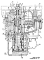
- the system for injecting molten material comprises a housing or casing 1 in which is disposed a fixed body 2.
- a device 3 for melting fusible material and a device 4 for injecting the molten material into a mold are mounted in the fixed body 2, the two devices respectively comprising a melting chamber 5 and an injection chamber 6 connected by a transfer channel 7 for the transfer of the molten material contained in the melting chamber, in the injection chamber .
- the fixed body 2 is disposed in the casing 1 and is kept at a predetermined distance from the internal surface of the casing 1 by spacing members 8, leaving a thermal insulation space 9 between the facing surfaces of the body 2 and housing 1.
- the body 2 comprises a cylindrical recess 12 in which is axially movable a tubular cylinder forming a drawer 13 closed on the upper side 14 oriented towards the mold and open at its lower end in which engages a piston element 15 made integral with the drawer 13 by screwing at 16.
- the piston 15 delimits inside the drawer cylinder 13 a space which forms the abovementioned injection chamber 6.
- the injection device comprises a nozzle produced in the form of a tube 18 which extends axially through the upper and solid part 14 of the drawer cylinder 13 while being integral with the latter.
- This tube extends by one end in the injection chamber 6 to a certain distance from the upper surface of the piston 15 which forms the bottom 19 of the injection chamber 6.
- the other end 21 of the tube 18 comes out at the top of the body 2, passing through a plug-forming member 22 closing the space at the top 12 of the body 2, to be introduced into the mold.
- Side walls 23 cylindrical of the chamber 6 have at the bottom 19 of the passages 24, for example three in number.
- the piston 15 is integrated in a cylinder assembly comprising a fixed cylindrical element 26 axially aligned with the recess 12 and in which the piston is axially movable against a return spring 27 in the direction of the recess 12 under the effect of a pressurized fluid introduced at 29 into a space 30 forming the working chamber of the jack.
- the element 26 is integral with the lower end of the body 2 with the interposition of a seal 31 and extends by a tubular part 32 axially in the interior of the body 2 to form the internal cylindrical surface of the device d injection, at the injection chamber 6.
- the recess 12 of the body 2 is shaped in a receiving zone of the tubular part 32 so that the internal cylindrical surfaces of the part 32 and of the recess 12 above the latter are axially aligned, and an annular chamber 34 is formed around the part 32 closed at the bottom by the front surface 35, of the element 26.
- the front surface 35 of the element 26 is located at the bottom 19 of the chamber 6 when the piston 15 occupies its rest position, shown in FIG. 2.
- the tubular part 32 has in its cylindrical wall passages 36 which lie opposite the passages 24 in the wall of the drawer cylinder 13, in the position shown of the injection device. These passages 36 open in the annular space 34 which communicates via the transfer channel 7 with the melting chamber 5.
- the piston 15 is axially displaceable from the rest position shown in FIG. 1 over a distance such that the passages 36 are closed by an external lateral surface of the drawer cylinder 13.
- the injection device comprises means for discharging the molten material from the melting chamber 6 into the mold through the nozzle tube 18 under the effect of a pressurized fluid admitted into the chamber 6 through a pipe which opens out.
- a pipe which opens out.
- the annular groove 40 is capable of coming into communication with a radial channel 41 opening into the recess 12 of the body 2 above the groove 40 and connected by a portion of internal channel (not shown) to a pipe 42 connected to a source of pressurized fluid ( Figure 2).
- the delivery device further comprises a diffuser 43 which is interposed in the upper part of the injection chamber 6 between the upper admissible level of the molten material and the arrival of the pipe 38 in the injection chamber 6.
- AXIAL hole 46 is provided in the body 2, intended to receive a heating element such as for example of the type with armored resistance cartridges.
- the melting device 3 comprises, in the melting chamber 5 above a portion forming a reservoir 45 of the molten material, a heating assembly 46 produced in the form of a heat exchanger with pins intended for melting fusible material into granules supplied by an arrangement comprising a flexible tube 47 located outside the casing 1 and a pipe-shaped element 48 disposed above the heating assembly 46.
- the bottom of the chamber 5 and thus the bottom of the tank 45 are formed by a sealed plate 49, the bottom of which is inclined so as to descend in the direction of the injection device 4.
- the plate 49 extends in the wall of the body 2 which delimits the cylindrical recess 12, pierced at the end of the plate 49, via the aforementioned transfer channel 7.
- the system according to the invention is equipped with a device for controlling its operation, which comprises a float 51 placed in the tank 45, which is fixed to one end of a lever 52 passing through the external wall of the fusion device at the level from the upper part of the plate 49 and articulated at 53 to this outer wall and the other end of which, extends outwardly through the casing 1, carries an element 54 forming part of a position detector device 55 of the proximity detector type.
- This device is adapted to emit a control signal when the float 51 is in determined lower and upper positions.
- the device controls the supply of the fusing device 3 with fusible material in the form of granules, and in the second case, it controls the sending of the pressurized fluid through the pipe 29 into the chamber 30 of the piston. 15 of the drawer cylinder 13.
- the plug 22, advantageously made of ceramic, of the recess 12 of the injection device 4 has in the outlet part 21 of the nozzle tube 18 a recess 57 whose bottom 58 is inclined in the direction of the melting chamber 5 with which it communicates through an orifice 59.
- the end 21 of the nozzle tube 18 has a deflection flange 60 of the molten material flowing from the end 21 towards the recess 57.
- the body 2 can be fixed by a ceramic pillar element 61 to a support, such as a table schematically represented at 62, using screws whose tapped holes are represented. at 63.
- the casing 1 is also equipped with a device 65 for mounting it on a work surface (not shown).
- a predetermined quantity of granular fusible material is supplied to the melting device 3 via the flexible tube 47 and the pipe element 48.
- the fusible material is melted by the heating element 46 in the form of a heat exchanger with pins, and the molten material thus obtained descends into the tank 45 via holes located between the pins of the heat exchanger.
- the transfer channel 7 which connects the melting chamber 5 and the injection chamber 6 being open, the molten material flows from the reservoir 45 to the injection chamber 6 until a predetermined level equilibrium and controlled by float 51 is reached.
- a pneumatic order is given and commands the sending of pressurized fluid through the line 29 which allows the piston 15 to be raised upwards by arming the return spring 27.
- the piston 15 transmits its movement to the cylinder forming a drawer 13 which closes the feed orifices 24 of the molten material, sealing the injection chamber 6 and driving the flexible nozzle tube 18 in contact with an injection point located on the mold with a force greater than the sum of the forces coming from the spring 27 and the back pressure that can be exerted on the material contained in the injection chamber 6.
- a second pneumatic order is given to allow the fluid under pressure to be brought in via the lines 42 and 41, through the annular groove 40 and the lines 38 and 39, to the diffuser 43, made of a porous material such than sintered bronze or ceramic.
- the latter distributes the pressure of the molten material, without creating preferred cooling zones, and under the pressure of the fluid, the molten material rises in the nozzle tube 18 to the mold and fills it.
- the quantity of molten material in reserve in 45 is one to two times equal to the quantity of material present in the injection chamber 6.
- the float 51 triggers the position detector 55 which instructs a granule distributor to send pneumatically and via the flexible tube 47 of the pipe-shaped element 48, a predetermined charge of granules of fusible material.
- the fusible material has a certain time for its melting and for returning the float 51 to the high position. The cycles can then start again.
- the system for injecting material into a mold of the present invention has many advantages. Indeed, the aforementioned melting device and the injection device combined in the same casing have a small footprint, which allows to have about fifteen similar systems on a workstation. Each of these systems can operate at its own rate thanks to the automation of the pellet feed and the dosing of the quantity to be injected. On the other hand, thanks to By automating the supply of fusible material and the metering of the injection, it is possible to avoid oxidation of the molten material.
- the system contained in the casing is easily graspable thanks to the thermal insulation by a layer of air between the casing and the devices integrated therein which allows on the one hand to lower the temperature of the casing and allows on the other hand to reduce the heat losses by convection and radiation in the system.
- the vertical arrangement avoids the presence of a shutter valve at the end of the flexible nozzle tube and that in the event of a melt flow during the injection, it can descend into the melt reservoir .
- the system according to the invention can use polymers and more particularly fusible adhesives which makes it possible to glue a product.
- the system of the invention is used to produce overmoldings on long and bulky objects, such as cable bundles, for sealing connectors, etc.
Landscapes
- Engineering & Computer Science (AREA)
- Mechanical Engineering (AREA)
- Manufacturing & Machinery (AREA)
- Physics & Mathematics (AREA)
- Thermal Sciences (AREA)
- Injection Moulding Of Plastics Or The Like (AREA)
- Processing And Handling Of Plastics And Other Materials For Molding In General (AREA)
- Moulds For Moulding Plastics Or The Like (AREA)
- Continuous Casting (AREA)
- Processing Of Solid Wastes (AREA)
Claims (13)
- System zum Spritzgießen eines geschmolzenen Materials in eine Aufnahmevorrichtung, wie eine Form, umfassend eine Schmelzvorrichtung (3) für das schmelzbare Material, welche eine Schmelzkammer enthält, und eine Spritzgießvorrichtung (4) für das geschmolzene Material, welche einen zylindrischen Hohlkörper (13) enthält, der eine Spritzgießkammer mit einer Ausgangsöffnung zur Beförderung des geschmolzenen Materials aus der Spritzgießkammer in die Form begrenzt, wobei der zylindrische Körper einen Schieber bildet, der in Längsrichtung in einem feststehenden Hüllkörper (2) bewegbar ist, sowie Mittel zur Beförderung des geschmolzenen Materials in die Form, wobei die Schmelz- und Spritzgießkammern parallel angeordnet sind und durch einen Überleitungskanal miteinander verbunden sind, der Teile umfaßt, welche durch die Seitenwände des beweglichen Körpers und des Hüllkörpers hindurchgehen, wobei die Verbindung hergestellt oder unterbrochen wird, wenn das Kanalteil des beweglichen Körpers dem Kanalteil der Hülle gegenüberliegt bzw. nicht gegenüberliegt, dadurch gekennzeichnet, daß die Schmelz- (5) und Spritzgießkammern (6) nebeneinanderliegen und an ihrer Basis durch den Überleitungskanal (7) miteinander in Verbindung stehen, wobei dieser in der Nähe des Bodens der Spritzgießkammer (6) mit einem geringen Abstand oberhalb des Bodens der Spritzgießkammer (6) derart mündet, daß er sich bei einer geringen Verschiebung des beweglichen Körpers nach oben in einer Verschlußposition des Überleitungskanals (7) befindet, und daß die Mittel zur Beförderung des geschmolzenen Materials in die Form Zufuhrmittel für ein Druckfluid in die Spritzgießkammer umfassen, welche das geschmolzene Material aus der Spritzgießkammer durch deren Ausgangsöffnung zum Spritzgießen des geschmolzenen Materials nach oben in die Form befördern.
- System nach Anspruch 1, dadurch gekennzeichnet, daß es eine Vorrichtung (51 bis 55) umfaßt, welche die Steuerung der Befüllung der Spritzgießkammer (6) und die Auslösung der Spritzgießvorrichtung (4) gewährleistet, wenn die Spritzgießkammer (6) eine vorgegebene Menge an geschmolzenem Material für das Spritzgießen enthält.
- System nach Anspruch 2, dadurch gekennzeichnet, daß die Vorrichtung zur Steuerung der Befüllung der Spritzgießkammer (6) und der Auslösung des Spritzgießens einen Schwimmer (51) umfaßt, der in der Schmelzkammer (5) angeordnet ist.
- System nach Anspruch 3, dadurch gekennzeichnet, daß der Schwimmer (51) an einem Ende an einer Hebelvorrichtung (52) befestigt ist, die in der Wand der Schmelzkammer (bei 53) schwenkbar befestigt ist, und an seinem anderen Ende Mittel trägt, die Teil eines Positionsdetektors (55) sind, mit dem eine Systemsteuerung-Signalgebervorrichtung verbunden ist.
- System nach Anspruch 4, dadurch gekennzeichnet, daß die Detektorvorrichtung (55) für den Nachweis einer unteren Standposition des Schwimmers (51) und zur Erzeugung eines Steuerungssignals für die Zufuhr von schmelzbarem Material von der Schmelzvorrichtung (3) ausgebildet ist und eine obere Standposition des Schwimmers (51) die Erzeugung eines Steuersignals für den Verschluß des Überleitungskanals (7) veranlaßt.
- System nach Anspruch 1, dadurch gekennzeichnet, daß die Beförderungsmittel eine Spritzdüse in Form eines Rohres (18) umfassen, das an dem Schiebezylinder (13) befestigt ist und sich innerhalb diesem in Längsrichtung erstreckt, von welchem ein Ende außerhalb der Spritzgießvorrichtung (4) mündet, während sein anderes Ende sich in die Spritzgießkammer (6) bis zu einem gewissen Niveau oberhalb des Bodens (19) der Spritzgießkammer (6) erstreckt, und daß der Raum in der Kammer über dem Niveau des geschmolzenen Materials zur Verbindung mit einer Druckfluidquelle geeignet ist, um das geschmolzene Material aus dieser Kammer durch das Rohr in die Form zu befördern.
- System nach Anspruch 6, dadurch gekennzeichnet, daß die Beförderungsmittel ferner einen Diffusor (43) umfassen, der in dem vorgenannten Raum zwischen dem Einlaß des Druckfluids und dem geschmolzenen Material angeordnet ist.
- System nach einem der vorangehenden Ansprüche, dadurch gekennzeichnet, daß der Schiebezylinder (13) in Längsrichtung durch ein Druckfluid gegen die Wirkung einer Rückstellfeder (27) in seine Verschlußposition verschiebbar ist.
- System nach einem der vorangehenden Ansprüche, dadurch gekennzeichnet, daß die Schmelzkammer (5) einen Behälter (45) für geschmolzenes Material umfaßt, der durch den Überleitungskanal (7) mit der Spritzgießkammer (6) und einer Anordnung (46) für das Schmelzen in Verbindung steht, die oberhalb des Behälters (45) angeordnet ist und das schmelzbare Material aufnimmt.
- System nach einem der Ansprüche 6 bis 9, dadurch gekennzeichnet, daß die Vorrichtung zur Auslösung des Spritzgießens Steuerungsmittel umfaßt, welche die Verbindung zwischen dem vorgenannten Raum der Spritzgießkammer (6) und der Druckfluidquelle herstellen, wenn der Schiebezylinder (13) eine vorgegebene Position nach dem Verschluß von Durchgängen (36) in der Wand des vorerwähnten feststehenden Körpers erreicht.
- System nach Anspruch 10, dadurch gekennzeichnet, daß der Schiebezylinder (13) an seiner zylindrischen Außenfläche eine ringförmige Auskehlung (40) umfaßt, die durch einen inneren Kanal (38, 39) mit dem obengenannten Raum verbunden ist, daß der feststehende Körper (2) in seiner zylindrischen Innenfläche eine Öffnung (41) aufweist, die mit der Druckfluidquelle verbunden ist, und daß die Auskehlung (40) und die Öffnung (41) derart angeordnet sind, daß die Auskehlung (40) nach dem Verschluß der Durchgänge (36) durch den Schiebezylinder (13) der Öffnung (41) gegenüberliegt.
- System nach einem der vorangehenden Ansprüche, dadurch gekennzeichnet, daß die Vorrichtungen (3 und 4) Teil desselben Körpers (2) sind, der in einem Gehäuse (1) angebracht ist, wobei ein Raum (9) bestehen bleibt, welcher für eine Wärmeisolierung sorgt.
- System nach einem der vorangehenden Ansprüche, dadurch gekennzeichnet, daß das äußere Ende der Spritzdüse (18) von einem Flansch (60) umgeben ist, der den Guß des geschmolzenen Materials in eine Aussparung (57) lenkt, die mit der Schmelzvorrichtung (3) in Verbindung steht.
Applications Claiming Priority (2)
| Application Number | Priority Date | Filing Date | Title |
|---|---|---|---|
| FR8911789 | 1989-09-08 | ||
| FR8911789A FR2651715B1 (fr) | 1989-09-08 | 1989-09-08 | Systeme pour injecter de la matiere fondue dans un dispositif recepteur tel qu'un moule. |
Publications (2)
| Publication Number | Publication Date |
|---|---|
| EP0417005A1 EP0417005A1 (de) | 1991-03-13 |
| EP0417005B1 true EP0417005B1 (de) | 1994-08-31 |
Family
ID=9385279
Family Applications (1)
| Application Number | Title | Priority Date | Filing Date |
|---|---|---|---|
| EP90402452A Expired - Lifetime EP0417005B1 (de) | 1989-09-08 | 1990-09-06 | System zum Spritzgiessen eines geschmolzenen Materials in eine Aufnahmevorrichtung wie eine Form |
Country Status (5)
| Country | Link |
|---|---|
| US (1) | US5116212A (de) |
| EP (1) | EP0417005B1 (de) |
| AT (1) | ATE110622T1 (de) |
| DE (1) | DE69012026T2 (de) |
| FR (1) | FR2651715B1 (de) |
Families Citing this family (3)
| Publication number | Priority date | Publication date | Assignee | Title |
|---|---|---|---|---|
| US5516271A (en) * | 1993-12-14 | 1996-05-14 | United Technologies Corporation | Apparatus for resin transfer molding |
| FR2717732B1 (fr) * | 1994-03-28 | 1996-05-31 | Jose Hernandez | Dispositif de fusion de matière thermoplastique puis d'injection de ladite matière dans un dispositif récepteur tel qu'un moule. |
| DE19511062A1 (de) * | 1995-03-25 | 1996-09-26 | S & T Apparate Und Vorrichtung | Vorrichtung zum Druckvergießen von aufschmelzbaren Kunststoffmaterialien |
Family Cites Families (6)
| Publication number | Priority date | Publication date | Assignee | Title |
|---|---|---|---|---|
| FR1000210A (fr) * | 1948-11-05 | 1952-02-11 | Nouveau système de moulage mécanique par injection de matières thermoplastiques et machine pour sa réalisation | |
| JPS497065B1 (de) * | 1964-11-20 | 1974-02-18 | ||
| DE2318386A1 (de) * | 1973-04-12 | 1974-10-31 | Moenus Maschf | Klebstoffauftragvorrichtung fuer schuhzwickmaschinen |
| FR2419815A1 (fr) * | 1978-03-17 | 1979-10-12 | Rostovsky Na Donu Inst Tekhn | Installation pour la fabrication de modeles consommables fusibles employes dans le moulage a la cire perdue |
| AU514078B2 (en) * | 1979-05-14 | 1981-01-22 | Nordson Corporation | Method for melting and dispensing thermoplastic material |
| US4557683A (en) * | 1984-05-22 | 1985-12-10 | Usm Corporation | Rotary plasticator ram injection machine |
-
1989
- 1989-09-08 FR FR8911789A patent/FR2651715B1/fr not_active Expired - Fee Related
-
1990
- 1990-09-06 AT AT90402452T patent/ATE110622T1/de not_active IP Right Cessation
- 1990-09-06 EP EP90402452A patent/EP0417005B1/de not_active Expired - Lifetime
- 1990-09-06 US US07/578,325 patent/US5116212A/en not_active Expired - Fee Related
- 1990-09-06 DE DE69012026T patent/DE69012026T2/de not_active Expired - Fee Related
Also Published As
| Publication number | Publication date |
|---|---|
| US5116212A (en) | 1992-05-26 |
| DE69012026T2 (de) | 1995-04-20 |
| FR2651715B1 (fr) | 1992-09-04 |
| DE69012026D1 (de) | 1994-10-06 |
| FR2651715A1 (fr) | 1991-03-15 |
| ATE110622T1 (de) | 1994-09-15 |
| EP0417005A1 (de) | 1991-03-13 |
Similar Documents
| Publication | Publication Date | Title |
|---|---|---|
| FR2548582A1 (fr) | Systeme de distribution chauffe pour moule d'injection | |
| FR2537497A1 (fr) | Buse a fermeture par aiguille pour moules de modulage par injection | |
| FR2491157A1 (fr) | Pompe a valve d'inversion actionnee par un double diaphragme | |
| FR2480636A1 (fr) | Unite d'injection pour machine a mouler sous pression | |
| EP1097663A1 (de) | Vorrichtung und Verfahren für Durchlauferhitzung eines Getränkes mit konstanter Temperatur | |
| EP0120171B1 (de) | Vorrichtung zum Reinigen eines Füllkopfes ohne seine Demontage | |
| EP0417005B1 (de) | System zum Spritzgiessen eines geschmolzenen Materials in eine Aufnahmevorrichtung wie eine Form | |
| EP1173383A1 (de) | Abfüllanlage mit verbesserter reinigungseinrichtung | |
| WO2011006999A1 (fr) | Systeme et procede d'injection d'un article moule multi-couche | |
| FR2571653A1 (fr) | Appareil de moulage par injection de precision, presentant de faibles dimensions | |
| FR2641227A1 (fr) | Buse de moule a obturation commandee pour l'injection de matiere plastique | |
| EP1631445B1 (de) | Ventil und zufuhrvorrichtung zum füllen eines formhohlraums mit einem polymerisierbaren material | |
| CH370004A (fr) | Installation pour la fabrication de récipients en matière plastique | |
| CH437016A (fr) | Machine pour constituer des joints d'étanchéité en matière plastique | |
| EP0893395A1 (de) | Elektroventil und dessen Anwendung in einer Abgabevorrichtung für kryogene Flüssigkeit sowie in einer Abfüllanlage | |
| EP0825128A2 (de) | Element zur Befestigung einer Abgabevorrichtung an einem Behälterhals | |
| EP0352156A1 (de) | Vorrichtung zum Spritzgiessen eines Kunststoffes in eine Form | |
| EP3302911B1 (de) | Vorrichtung mit verbesserten dichtungsmitteln zur verteilung von thermoplastischem material | |
| FR2594067A1 (fr) | Appareil d'extrusion a deux extrudeuses | |
| EP0286481A1 (de) | Verfahren und Vorrichtung zum Befestigen eines Metallklotzes auf einer Oberfläche einer ophthalmischen Linse durch Aufformen von geschmolzenem Metall | |
| FR2703150A1 (fr) | Dispositif de dosage, notamment pour produits visqueux. | |
| LU84559A1 (fr) | Remplisseuse-doseuse,notamment pour la distribution de quantites dosees de produits alimentaires | |
| EP0343059B1 (de) | Verfahren und Vorrichtung zum Einnehmen einer Flüssigkeit, wie Quellwasser | |
| FR2532583A1 (fr) | Dispositif d'injection et de chauffage a cartouche pour un distributeur d'injection a chenaux de coulee chaude | |
| EP0493160B1 (de) | Anlage zum Spritzgiessen von Verbundwerkstoff |
Legal Events
| Date | Code | Title | Description |
|---|---|---|---|
| PUAI | Public reference made under article 153(3) epc to a published international application that has entered the european phase |
Free format text: ORIGINAL CODE: 0009012 |
|
| AK | Designated contracting states |
Kind code of ref document: A1 Designated state(s): AT BE CH DE DK ES FR GB GR IT LI LU NL SE |
|
| 17P | Request for examination filed |
Effective date: 19910802 |
|
| RAP1 | Party data changed (applicant data changed or rights of an application transferred) |
Owner name: HERNANDEZ, JOSE |
|
| 17Q | First examination report despatched |
Effective date: 19930222 |
|
| GRAA | (expected) grant |
Free format text: ORIGINAL CODE: 0009210 |
|
| AK | Designated contracting states |
Kind code of ref document: B1 Designated state(s): AT BE CH DE DK ES FR GB GR IT LI LU NL SE |
|
| PG25 | Lapsed in a contracting state [announced via postgrant information from national office to epo] |
Ref country code: IT Free format text: LAPSE BECAUSE OF FAILURE TO SUBMIT A TRANSLATION OF THE DESCRIPTION OR TO PAY THE FEE WITHIN THE PRESCRIBED TIME-LIMIT;WARNING: LAPSES OF ITALIAN PATENTS WITH EFFECTIVE DATE BEFORE 2007 MAY HAVE OCCURRED AT ANY TIME BEFORE 2007. THE CORRECT EFFECTIVE DATE MAY BE DIFFERENT FROM THE ONE RECORDED. Effective date: 19940831 Ref country code: ES Free format text: THE PATENT HAS BEEN ANNULLED BY A DECISION OF A NATIONAL AUTHORITY Effective date: 19940831 Ref country code: NL Effective date: 19940831 Ref country code: GR Free format text: LAPSE BECAUSE OF FAILURE TO SUBMIT A TRANSLATION OF THE DESCRIPTION OR TO PAY THE FEE WITHIN THE PRESCRIBED TIME-LIMIT Effective date: 19940831 Ref country code: AT Effective date: 19940831 Ref country code: DK Effective date: 19940831 |
|
| REF | Corresponds to: |
Ref document number: 110622 Country of ref document: AT Date of ref document: 19940915 Kind code of ref document: T |
|
| PG25 | Lapsed in a contracting state [announced via postgrant information from national office to epo] |
Ref country code: BE Effective date: 19940930 Ref country code: LI Effective date: 19940930 Ref country code: LU Free format text: LAPSE BECAUSE OF NON-PAYMENT OF DUE FEES Effective date: 19940930 Ref country code: CH Effective date: 19940930 |
|
| REF | Corresponds to: |
Ref document number: 69012026 Country of ref document: DE Date of ref document: 19941006 |
|
| PG25 | Lapsed in a contracting state [announced via postgrant information from national office to epo] |
Ref country code: SE Effective date: 19941130 |
|
| GBT | Gb: translation of ep patent filed (gb section 77(6)(a)/1977) |
Effective date: 19941205 |
|
| NLV1 | Nl: lapsed or annulled due to failure to fulfill the requirements of art. 29p and 29m of the patents act | ||
| BERE | Be: lapsed |
Owner name: HERNANDEZ JOSE Effective date: 19940930 |
|
| REG | Reference to a national code |
Ref country code: CH Ref legal event code: PL |
|
| PLBE | No opposition filed within time limit |
Free format text: ORIGINAL CODE: 0009261 |
|
| STAA | Information on the status of an ep patent application or granted ep patent |
Free format text: STATUS: NO OPPOSITION FILED WITHIN TIME LIMIT |
|
| 26N | No opposition filed | ||
| PGFP | Annual fee paid to national office [announced via postgrant information from national office to epo] |
Ref country code: GB Payment date: 19950831 Year of fee payment: 6 |
|
| PGFP | Annual fee paid to national office [announced via postgrant information from national office to epo] |
Ref country code: FR Payment date: 19950922 Year of fee payment: 6 |
|
| PGFP | Annual fee paid to national office [announced via postgrant information from national office to epo] |
Ref country code: DE Payment date: 19950928 Year of fee payment: 6 |
|
| PG25 | Lapsed in a contracting state [announced via postgrant information from national office to epo] |
Ref country code: GB Effective date: 19960906 |
|
| PG25 | Lapsed in a contracting state [announced via postgrant information from national office to epo] |
Ref country code: FR Effective date: 19960930 |
|
| GBPC | Gb: european patent ceased through non-payment of renewal fee |
Effective date: 19960906 |
|
| PG25 | Lapsed in a contracting state [announced via postgrant information from national office to epo] |
Ref country code: DE Effective date: 19970603 |
|
| REG | Reference to a national code |
Ref country code: FR Ref legal event code: ST |
|
| REG | Reference to a national code |
Ref country code: FR Ref legal event code: ST |