EP0417380A2 - Behälter zum Verpacken von Lebensmitteln - Google Patents
Behälter zum Verpacken von Lebensmitteln Download PDFInfo
- Publication number
- EP0417380A2 EP0417380A2 EP90101316A EP90101316A EP0417380A2 EP 0417380 A2 EP0417380 A2 EP 0417380A2 EP 90101316 A EP90101316 A EP 90101316A EP 90101316 A EP90101316 A EP 90101316A EP 0417380 A2 EP0417380 A2 EP 0417380A2
- Authority
- EP
- European Patent Office
- Prior art keywords
- layer
- resin layer
- container
- flange
- heat
- Prior art date
- Legal status (The legal status is an assumption and is not a legal conclusion. Google has not performed a legal analysis and makes no representation as to the accuracy of the status listed.)
- Granted
Links
Images





Classifications
-
- B—PERFORMING OPERATIONS; TRANSPORTING
- B32—LAYERED PRODUCTS
- B32B—LAYERED PRODUCTS, i.e. PRODUCTS BUILT-UP OF STRATA OF FLAT OR NON-FLAT, e.g. CELLULAR OR HONEYCOMB, FORM
- B32B15/00—Layered products comprising a layer of metal
- B32B15/04—Layered products comprising a layer of metal comprising metal as the main or only constituent of a layer, which is next to another layer of the same or of a different material
- B32B15/08—Layered products comprising a layer of metal comprising metal as the main or only constituent of a layer, which is next to another layer of the same or of a different material of synthetic resin
-
- B—PERFORMING OPERATIONS; TRANSPORTING
- B32—LAYERED PRODUCTS
- B32B—LAYERED PRODUCTS, i.e. PRODUCTS BUILT-UP OF STRATA OF FLAT OR NON-FLAT, e.g. CELLULAR OR HONEYCOMB, FORM
- B32B15/00—Layered products comprising a layer of metal
- B32B15/20—Layered products comprising a layer of metal comprising aluminium or copper
-
- B—PERFORMING OPERATIONS; TRANSPORTING
- B32—LAYERED PRODUCTS
- B32B—LAYERED PRODUCTS, i.e. PRODUCTS BUILT-UP OF STRATA OF FLAT OR NON-FLAT, e.g. CELLULAR OR HONEYCOMB, FORM
- B32B27/00—Layered products comprising a layer of synthetic resin
- B32B27/06—Layered products comprising a layer of synthetic resin as the main or only constituent of a layer, which is next to another layer of the same or of a different material
- B32B27/08—Layered products comprising a layer of synthetic resin as the main or only constituent of a layer, which is next to another layer of the same or of a different material of synthetic resin
-
- B—PERFORMING OPERATIONS; TRANSPORTING
- B32—LAYERED PRODUCTS
- B32B—LAYERED PRODUCTS, i.e. PRODUCTS BUILT-UP OF STRATA OF FLAT OR NON-FLAT, e.g. CELLULAR OR HONEYCOMB, FORM
- B32B27/00—Layered products comprising a layer of synthetic resin
- B32B27/32—Layered products comprising a layer of synthetic resin comprising polyolefins
-
- B—PERFORMING OPERATIONS; TRANSPORTING
- B32—LAYERED PRODUCTS
- B32B—LAYERED PRODUCTS, i.e. PRODUCTS BUILT-UP OF STRATA OF FLAT OR NON-FLAT, e.g. CELLULAR OR HONEYCOMB, FORM
- B32B37/00—Methods or apparatus for laminating, e.g. by curing or by ultrasonic bonding
- B32B37/14—Methods or apparatus for laminating, e.g. by curing or by ultrasonic bonding characterised by the properties of the layers
- B32B37/15—Methods or apparatus for laminating, e.g. by curing or by ultrasonic bonding characterised by the properties of the layers with at least one layer being manufactured and immediately laminated before reaching its stable state, e.g. in which a layer is extruded and laminated while in semi-molten state
- B32B37/153—Methods or apparatus for laminating, e.g. by curing or by ultrasonic bonding characterised by the properties of the layers with at least one layer being manufactured and immediately laminated before reaching its stable state, e.g. in which a layer is extruded and laminated while in semi-molten state at least one layer is extruded and immediately laminated while in semi-molten state
-
- B—PERFORMING OPERATIONS; TRANSPORTING
- B32—LAYERED PRODUCTS
- B32B—LAYERED PRODUCTS, i.e. PRODUCTS BUILT-UP OF STRATA OF FLAT OR NON-FLAT, e.g. CELLULAR OR HONEYCOMB, FORM
- B32B7/00—Layered products characterised by the relation between layers; Layered products characterised by the relative orientation of features between layers, or by the relative values of a measurable parameter between layers, i.e. products comprising layers having different physical, chemical or physicochemical properties; Layered products characterised by the interconnection of layers
- B32B7/02—Physical, chemical or physicochemical properties
- B32B7/027—Thermal properties
-
- B—PERFORMING OPERATIONS; TRANSPORTING
- B65—CONVEYING; PACKING; STORING; HANDLING THIN OR FILAMENTARY MATERIAL
- B65D—CONTAINERS FOR STORAGE OR TRANSPORT OF ARTICLES OR MATERIALS, e.g. BAGS, BARRELS, BOTTLES, BOXES, CANS, CARTONS, CRATES, DRUMS, JARS, TANKS, HOPPERS, FORWARDING CONTAINERS; ACCESSORIES, CLOSURES, OR FITTINGS THEREFOR; PACKAGING ELEMENTS; PACKAGES
- B65D65/00—Wrappers or flexible covers; Packaging materials of special type or form
- B65D65/38—Packaging materials of special type or form
- B65D65/40—Applications of laminates for particular packaging purposes
-
- B—PERFORMING OPERATIONS; TRANSPORTING
- B32—LAYERED PRODUCTS
- B32B—LAYERED PRODUCTS, i.e. PRODUCTS BUILT-UP OF STRATA OF FLAT OR NON-FLAT, e.g. CELLULAR OR HONEYCOMB, FORM
- B32B2307/00—Properties of the layers or laminate
- B32B2307/50—Properties of the layers or laminate having particular mechanical properties
- B32B2307/54—Yield strength; Tensile strength
-
- B—PERFORMING OPERATIONS; TRANSPORTING
- B32—LAYERED PRODUCTS
- B32B—LAYERED PRODUCTS, i.e. PRODUCTS BUILT-UP OF STRATA OF FLAT OR NON-FLAT, e.g. CELLULAR OR HONEYCOMB, FORM
- B32B2311/00—Metals, their alloys or their compounds
- B32B2311/24—Aluminium
-
- B—PERFORMING OPERATIONS; TRANSPORTING
- B32—LAYERED PRODUCTS
- B32B—LAYERED PRODUCTS, i.e. PRODUCTS BUILT-UP OF STRATA OF FLAT OR NON-FLAT, e.g. CELLULAR OR HONEYCOMB, FORM
- B32B2439/00—Containers; Receptacles
- B32B2439/70—Food packaging
-
- B—PERFORMING OPERATIONS; TRANSPORTING
- B65—CONVEYING; PACKING; STORING; HANDLING THIN OR FILAMENTARY MATERIAL
- B65D—CONTAINERS FOR STORAGE OR TRANSPORT OF ARTICLES OR MATERIALS, e.g. BAGS, BARRELS, BOTTLES, BOXES, CANS, CARTONS, CRATES, DRUMS, JARS, TANKS, HOPPERS, FORWARDING CONTAINERS; ACCESSORIES, CLOSURES, OR FITTINGS THEREFOR; PACKAGING ELEMENTS; PACKAGES
- B65D2577/00—Packages formed by enclosing articles or materials in preformed containers, e.g. boxes, cartons, sacks, bags
- B65D2577/10—Container closures formed after filling
- B65D2577/20—Container closures formed after filling by applying separate lids or covers
- B65D2577/2025—Multi-layered container, e.g. laminated, coated
- B65D2577/2033—Multi-layered container, e.g. laminated, coated with one or more layers of container being torn off upon initial opening
-
- B—PERFORMING OPERATIONS; TRANSPORTING
- B65—CONVEYING; PACKING; STORING; HANDLING THIN OR FILAMENTARY MATERIAL
- B65D—CONTAINERS FOR STORAGE OR TRANSPORT OF ARTICLES OR MATERIALS, e.g. BAGS, BARRELS, BOTTLES, BOXES, CANS, CARTONS, CRATES, DRUMS, JARS, TANKS, HOPPERS, FORWARDING CONTAINERS; ACCESSORIES, CLOSURES, OR FITTINGS THEREFOR; PACKAGING ELEMENTS; PACKAGES
- B65D2577/00—Packages formed by enclosing articles or materials in preformed containers, e.g. boxes, cartons, sacks, bags
- B65D2577/10—Container closures formed after filling
- B65D2577/20—Container closures formed after filling by applying separate lids or covers
- B65D2577/2075—Lines of weakness or apertures
- B65D2577/2083—Lines of weakness or apertures in container flange
-
- Y—GENERAL TAGGING OF NEW TECHNOLOGICAL DEVELOPMENTS; GENERAL TAGGING OF CROSS-SECTIONAL TECHNOLOGIES SPANNING OVER SEVERAL SECTIONS OF THE IPC; TECHNICAL SUBJECTS COVERED BY FORMER USPC CROSS-REFERENCE ART COLLECTIONS [XRACs] AND DIGESTS
- Y10—TECHNICAL SUBJECTS COVERED BY FORMER USPC
- Y10T—TECHNICAL SUBJECTS COVERED BY FORMER US CLASSIFICATION
- Y10T428/00—Stock material or miscellaneous articles
- Y10T428/13—Hollow or container type article [e.g., tube, vase, etc.]
- Y10T428/1352—Polymer or resin containing [i.e., natural or synthetic]
- Y10T428/1355—Elemental metal containing [e.g., substrate, foil, film, coating, etc.]
-
- Y—GENERAL TAGGING OF NEW TECHNOLOGICAL DEVELOPMENTS; GENERAL TAGGING OF CROSS-SECTIONAL TECHNOLOGIES SPANNING OVER SEVERAL SECTIONS OF THE IPC; TECHNICAL SUBJECTS COVERED BY FORMER USPC CROSS-REFERENCE ART COLLECTIONS [XRACs] AND DIGESTS
- Y10—TECHNICAL SUBJECTS COVERED BY FORMER USPC
- Y10T—TECHNICAL SUBJECTS COVERED BY FORMER US CLASSIFICATION
- Y10T428/00—Stock material or miscellaneous articles
- Y10T428/24—Structurally defined web or sheet [e.g., overall dimension, etc.]
- Y10T428/24942—Structurally defined web or sheet [e.g., overall dimension, etc.] including components having same physical characteristic in differing degree
- Y10T428/2495—Thickness [relative or absolute]
- Y10T428/24967—Absolute thicknesses specified
-
- Y—GENERAL TAGGING OF NEW TECHNOLOGICAL DEVELOPMENTS; GENERAL TAGGING OF CROSS-SECTIONAL TECHNOLOGIES SPANNING OVER SEVERAL SECTIONS OF THE IPC; TECHNICAL SUBJECTS COVERED BY FORMER USPC CROSS-REFERENCE ART COLLECTIONS [XRACs] AND DIGESTS
- Y10—TECHNICAL SUBJECTS COVERED BY FORMER USPC
- Y10T—TECHNICAL SUBJECTS COVERED BY FORMER US CLASSIFICATION
- Y10T428/00—Stock material or miscellaneous articles
- Y10T428/31504—Composite [nonstructural laminate]
- Y10T428/31678—Of metal
Definitions
- the present invention relates to food packaging containers for use in packaging, for example, desserts, foods to be cooked or cooked foods.
- Conventional food packaging containers were prepared from a laminate sheet which was composed of aluminum foil and a synthetic resin layer joined to one surface of the foil.
- the aluminum foil had a greater thickness than the synthetic resin layer.
- the main object of the present invention is to provide a food packaging container free of the above problems.
- the food packaging container of the invention has a flanged container body prepared from a laminate sheet comprising a layer of aluminum foil and at least one thermoplastic resin layer joined to one surface of the layer, by deep-drawing the laminate sheet with the resin layer inside.
- the container is characterized in that the aluminum foil layer of the laminate sheet comprises an aluminum foil 40 - 200 ⁇ m in thickness, 9.0 - 25.0 kgf/mm2 in tensile strength, 2.5 - 9.5 kgf/mm2 in proof stress, 10 - 40% in elongation and up to 7% in earing, and that the thermoplastic resin layer of the sheet comprises a thermoplastic resin 100 - 500 ⁇ m in thickness, 0.92 - 1.08 in the ratio of modulus of elasticity in tension in the machine direction (MD) to that in the transverse direction (TD)(MD/TD ratio of modulus of elasticity in tension), 0.60 - 1.40 in the MD/TD ratio of elongation and 0.40 - 1.60 in the MD/TD ratio of breaking strength.
- MD
- “Earing” is the measure of the height (h e ) and the height of the ear valley (h v ) on the cup with an accuracy of ⁇ 0.05 mm, calculated according to the following formula: wherein h e is the mean height of the ear in mm and h v is the mean height of the ear valley in mm.
- the food packaging container is at least 40% in drawing ratio, i.e., in the ratio of the depth of the container body to the opening diameter of the body (H/W).
- the thermoplastic resin layer is given a larger thickness than the aluminum foil layer.
- the aluminum foil and the resin layer forming the laminate sheet have sufficient strength, permitting the sheet to be deep-drawn into food packaging containers free of wrinkling. Accordingly, even if an increased blank holder pressure is applied to the flange, the sheet can be shaped into the container satisfactorily without developing any fracture.
- the container obtained has excellent shape retentivity and is resistant to deformation by impact or the like during transport or handling. Further since the aluminum foil of the laminate sheet has no anisotropy, the material can be deep-drawn uniformly circumferentially of the flange, consequently giving a uniform width to the resulting container without causing any fracture to the material.
- the flange can be uniform in the residual strain of the material. As a result, no undulation occurs in the flange in the case where the container is heated for sterilization with retorted food placed therein. Further because the laminate sheet is amenable to cold deep drawing, food packaging containers can be manufactured with a very high efficiency and high productivity.
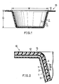
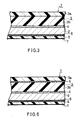
- a food packaging container 10 has a container body 11 having a flange 12 and prepared from a laminate sheet 1 which comprises an aluminum foil layer 2 and at least one thermoplastic resin layer 3 joined to one surface of the layer 2, by subjecting the sheet 1 to a cold deep-drawing process with the resin layer 3 inside.
- the aluminum foil layer 2 of the laminate sheet 1 comprises an aluminum foil which is 40 - 200 ⁇ m in thickness, 9.0 - 25.0 kgf/mm2 in tensile strength, 2.5 - 9.5 kgf/mm2 in proof stress, 10 - 40% in elongation and up to 7% in earing.
- the thermoplastic resin layer 3 of the sheet 1 comprises a thermoplastic resin which is 100 - 500 ⁇ m in thickness, 0.92 - 1.08 in the ratio of modulus of elasticity in tension in the machine direction (MD) to that in the transverse direction (TD) (i.e., in the MD/TD ratio of modulus of elasticity in tension), 0.60 - 1.40 in the MD/TD ratio of elongation and 0.40 - 1.60 in the MD/TD ratio of breaking strength.
- MD machine direction
- TD transverse direction
- the aluminum foil layer 2 of the laminate sheet 1 when less than 40 ⁇ m in thickness, is insuffi cient in strength, is liable to fracture when the container 10 is formed and renders the resulting container 10 unable to retain its shape owing to the springback of the resin layer 3.
- the drawing ratio of the food packaging container 10 i.e., the ratio of the depth of the container body 11 to the opening diameter thereof (H/W, see Fig. 1)
- H/W the ratio of the depth of the container body 11 to the opening diameter thereof
- the thickness of the aluminum foil layer 2 be 80 to 200 ⁇ m so as to prevent the flange 12 from undulation when the container obtained is sterilized by boiling or when the container is sterilized by retorting with food enclosed therein.
- the aluminum foil layer 2 is less than 9.0 kgf/mm2 in tensile strength and less than 2.5 kgf/mm2 in proof stress, the layer is insufficient in strength, therefore low in impact resistance and in compression resistance and prone to deformation during transport or handling. Further when exceeding 25.0 kgf/mm2 in tensile strength and 9.5 kgf/mm2 in proof stress, the aluminum foil layer 2 has excessive strength, and is difficult to shape and undesirable. Further if less than 10% in elongation, the aluminum foil layer 2 will break during deep drawing, whereas if excedding 40% in elongation, the foil layer 2 is lower in strength and therefore undesirable.
- the material When the earing ratio of the aluminum layer 2 is over 7%, the material will not be drawn uniformly over the entire circumference of the flange but so-called ears will be formed markedly to render the flange uneven in width on drawing, making it impossible to form a uniform curled edge at the outer end of the flange.
- the thermoplastic resin layer 3 of the laminate sheet 1 is made of a thermoplastic resin.
- resins are polyolefins such as polypropylene and polyethylene, polyester, polyvinyl chloride, polycarbonate, polystyrene, copolymers of such resins, and blends of such resins in suitable proportions.
- the thermoplastic resin layer 3 has a thickness of 100 - 500 ⁇ m, preferably 200 - 400 ⁇ m, in its entirety. When less than 100 ⁇ m in thickness, the resin layer 3 is insufficient in strength, failing to enable the container 10 to retain its shape as expected, and is less effective to prevent the container from deformation during transport or handling. Thicknesses exceeding 500 ⁇ m result in increased spring back and make the material unamenable to cold deep drawing and unable to form containers with high productivity.
- thermoplastic resin layer 3 is given a larger thickness than the aluminum foil layer 2.
- the thermoplastic resin layer 3 is 0.92 - 1.08 in the MD/TD ratio of modulus of elasticity in tension, 0.60 - 1.40 in the MD/TD ratio of elongation and 0.40 - 1.60 in the MD/TD ratio of breaking strength.
- the layer is anisotropic, with the result that the material will not be drawn uniformly circumferentially of the flange to give an uneven width to the resulting flange 12.
- the resin layer 3 is then also prone to fracture.
- the food packaging container 10 thus prepared from the laminate sheet 1 has an excellent barrier property due to the presence of the aluminum foil layer 2, so that the contents thereof, such as dessert, food to be cooked or cooked food, can be preserved effectively for a prolonged period of time.
- the container With the thermoplastic resin layer 3 joined to the aluminum foil layer 2, the container has exceedingly high strength and is resistant to denting under impact.
- the use of the aluminum foil layer 2 gives a sophisticated esthetic appearance to the container.
- the container can be formed by deep drawing. When the container obtained by deep drawing even with a drawing ratio (depth H/opening diameter W) of at least 40% is sterilized by boiling, or by retorting with food enclosed therein, the flange of the container remains free of any wrinkling. The container is therefore excellent in quality and can be manufactured in quantities with high productivity.
- thermoplastic resin layer 3 comprises (I) a single thermoplastic resin, (II) unstretched co-extruded thermoplastic resins in the form of at least two layers, or (III) at least two thermoplastic resin layers which are separably joined together with an adhesive layer provided therebetween.
- the thermoplastic resin layer 3 of the laminate sheet 1 comprises unstretched co-extruded thermoplastic resins (II), i.e., a first resin layer 3a on the surface to be joined to a heat-sealing material layer 22 of a lid 21, and a second resin layer 3b separably joined to the rear side of the layer 3a.
- the aluminum foil layer 2 is joined to the resin layer 3 with an adhesive layer 4 provided therebetween.
- the flange 12 has along the entire circumference thereof an annular incision 15 of V-shaped cross section formed in the first thermoplastic resin layer 3a and positioned close to the opening-defining inner periphery of the container body 11.
- thermoplastic resins such as polypropylene, polyethylene, polyester, polyvinyl chloride, polycarbonate, etc. It is especially desirable to use high-density polyethylene for the resin layer 3a on the surface side, and one of polypropylene and a mixture of polypropylene and polyethylene for the resin layer 3b to be separably joined to the rear side of the layer 3a.
- the polypropylene to polyethylene ratio of the mixture is, for example, 50:50 to 97:3 by weight.
- Other thermoplastic resins may be used in combination in the form of at least two layers.
- the peel strength between the the first thermoplastic resin layer 3a on the front side and the second thermoplastic resin layer 3b on the rear side is 500 - 1500 g/ 15 mm width, preferably 700 - 900 g/15 mm width.
- thermoplastic resins (II) are unstretched, these resins are diminished in orientation, are therefore satisfactorily shapable and undergo plastic deformation highly coextensively with the aluminum foil layer 2. Accordingly, the material can be shaped by cold deep drawing and has the advantage that the food packaging container 10 with a great depth can be manufactured with a very high efficiency and excellent productivity.
- the incision 15 to be provided in the flange 12 close to the opening-defining edge of the container body 11 can be formed, for example, by cutting off a portion of the first resin layer 3a with a blade or thermally removing a portion thereof.
- the incision 15 need not always be V-shaped but optional in cross section.
- the illustrated separating incision 15 may alternatively be formed in the opening edge portion itself of the container body 11.
- Examples of adhesives useful for forming the adhesive layer 4 to be interposed between the aluminum foil layer 2 and the thermoplastic resin layer 3 of unstretched co-extruded resins are urethane and polyester adhesives, maleinized polypropylene and ionomers, i.e. monoolefin-unsaturated carboxylic acid copolymer resins or metal salts thereof (see, for example, Examined Japanese Patent Publication SHO 61-54587).
- the adhesive layer 4 is formed, for example, by one of the following three methods.
- the adhesive is applied to a thickness of 5 to 50 ⁇ m, preferably 10 to 20 ⁇ m.
- thermoplastic resin layer 3 as an adherend.
- the monoolefin-unsaturated carboxylic acid copolymer resins or metal salts thereof serving as adhesives are as follows.
- the monoolefin-unsaturated carboxylic acid copolymer resins consist basically of a resin obtained by copolymerizing an ⁇ -monoolefin, such as ethylene, propylene, 1-butene, isobutane, 4-methyl-1-pentene, 1-hexene or 1-heptene, with an ⁇ , ⁇ -unsaturated carboxylic acid such as acrylic acid, methacrylic acid, ethacrylic acid or crotonic acid.
- Typical of such resins are ethylene-acrylic acid copolymer resin and ethylene-methacrylic acid copolymer resin. These copolymer resins are 1000 to 200000 in molecular weight and have an unsaturated carboxylic acid content of 1 to 30% by weight, preferably 2 to 20% by weight.
- metal salts of the monoolefin-unsaturated carboxylic acid copolymer resins are ion-crosslinked resins, i.e., ionomers obtained by neutralizing the carboxyl group of the copolymer resin with sodium, potassium or like alkali metal ion or zinc, magnesium or like alkaline earth metal ion.
- the degree of neutralization with the metal ion is, for example, 0.5 to 40%.
- Such ionomer resins have a carboxylic acid content of 5 to 18% and an ionization degree of several % to 90%.
- the monoolefin-unsaturated carboxylic acid copolymer resin or the metal salt thereof may contain an inorganic compound.
- inorganic compounds are oxides, hydroxides, carbonates and sulfates of magnesium, calcium, aluminum, titanium and silicon, talc, clay, feldspar, mica, barite and the like.
- the carbonate of calcium and talc are especially desirable to use.
- the inorganic compound is 0.1 to 50 ⁇ m, preferably 0.5 to 30 ⁇ m, in means particle size.
- the copolymer resin or metal salt thereof is to contain the inorganic compound, up to 30 parts by weight, usually 0.1 to 10 parts by weight, preferably 1 to 5 parts by weight, of the inorganic compound is to be admixed with 100 parts by weight of the copolymer resin or metal salt.
- the adhesive layer 4 especially when prepared from the monoolefin unsaturated carboxylic acid copolymer resin or metal salt thereof, has a sufficient thickness and reliably bonds the layer 3 to the foil layer 2 like urethane adhesives even if the surface of the adherend bears gel-like projections or extraneous matter, consequently preventing separation of the thermoplastic resin layer 3 during shaping.
- the resin layer 3 and the adhesive layer 4 of monoolefin-unsaturated carboxylic acid copolymer resin or metal salt thereof have a sufficient thickness. Accordingly, in the case where a food containing a highly penetrating flavoring or the like is hermetically enclosed in the container, the resin layer 3 will not separate off during the preservation of the food. Thus, the container has an exceedingly high quality.
- the aluminum foil layer 2 is formed over its outer surface with a protective covering layer 7 for protecting the aluminum foil layer 2.
- the layer 7 is formed by coating the foil layer 2 with a solution of a synthetic resin having high resistance to chemicals and weather, or by bonding a layer of the resin to the foil layer 2 with an adhesive layer 8.
- the protective covering layer 7 is 1 to 50 ⁇ m in thickness.
- the protective layer 7 is, for example, a coating of epoxy resin or nitrocellulose, it is preferable to apply the resin in an amount of 1 to 3 g/m2.
- the layer is 12 to 16 ⁇ m when made of polyethylene phthalate film, or 20 to 50 ⁇ m when made of unstretched polypropylene film, or 15 to 20 ⁇ m when made of nylon film.
- common urethane, polyester or like adhesive is used for the adhesive layer 8 for bonding the protective covering layer 7 to the outer surface of the aluminum foil layer 2.
- a suitable kind of adhesive is used in accordance with the kind of the adherend.
- the thickness of the protective covering layer 7 may be larger than 50 ⁇ m.
- the synthetic resin forming the layer 7 must have the same mechanical properties as the thermoplastic resin layer 3 of the laminate sheet 1.
- a printing layer 6 is provided between the aluminum foil layer 2 and the protective covering layer 7.
- the printing layer 6 is formed, for example, with a polyvinyl chloride-vinyl. acetate, nitrocellulose, urethane or like ink.
- the container having contents, such as dessert, food to be cooked or cooked food (not shown), placed therein is covered with the lid 21 having the heat-sealing material layer 22 on its lower surface.
- the portion of the first thermoplastic resin layer 3a of the container body flange 12 outward from the incision 15 and the portion 22A of heat-sealing material layer 22 corresponding thereto are heat-sealed by being fused with the heat-pressing member 25 of a heat-sealing device.
- the two thermoplastic resin layers 3a and 3b of the unstretched co-extruded resin layer 3 are easily separably in intimate contact with each other. More specifically, the adhesive strength between the innermost first resin layer 3a of the container body 11 and the second resin layer 3b thereof is smaller than the adhesive strength between the first resin layer 3a and the heat-sealing material layer 22 of the lid 21 of the fused portion outward from the incision 15, so that the portion of the first resin layer 3a on the surface side of the layer 3 outward from the incision 15 can be easily peeled, as joined to the heat-sealing material layer 22 of the lid 21, off the second resin layer 3b of the container body 11 when an opening knob portion 23 of the lid 21 is pulled upward.
- thermoplastic resin layer 3 of a modified laminate sheet 1 comprises two layers 3a and 3b of different thermoplastic resins (III) which are separably joined together by a joint layer 5.
- An aluminum foil layer 2 is bonded to the layer 3 by an adhesive layer 4.
- thermoplastic resins useful for forming the first layer 3a on the surface side of the layer 3 and the second layer 3b on the rear side of the layer 3a are those exemplified above, i.e., polypropylene, polyethylene, nylon, polyvinyl chloride, polycarbonate and the like.
- the joint layer 5 for separably joining together the first layer 3a on the surface side of the thermoplastic resin layer 3 and the second layer 3b on the rear side thereof.
- the joint layer 5 may be a usual adhesive layer of urethane, polyester or like adhesive, or may be formed by coating one surface of a layer of the monoolefin-unsaturated carboxylic acid copolymer resin or metal salt thereof to be described later, for example, with a silicone resin coating composition assuring ease of peeling.
- the peel strength between the first layer 3a of the thermoplastic resin layer 3 and the second layer 3b thereof is 500 - 1500 g/15 mm width, preferably 700 - 900 g/15 mm width.
- the adhesive for forming the adhesive layer 4 for joining the layer 3 of two kinds of thermoplastic resins (III) to the aluminum foil layer 2 can be the same as the one used for forming the adhesive layer 4 for bonding the aluminum foil layer 2 to the layer 3 of unstretched co-extruded thermoplastic resins (II) already mentioned.
- useful resins it is desirable to use the aforementioned monoolefin-unsaturated carboxylic acid copolymer resin or metal salt thereof.
- a protective covering layer 7 is formed over the outer surface of the aluminum foil layer 2 with an adhesive layer 8 and a printing layer 6 interposed therebetween.
- These protective covering layer 7, adhesive layer 8 and printing layer 6 are the same as those of the embodiment described with reference to Figs. 2 to 5.
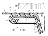
- Fig. 9 shows a food packaging container 10 prepared from a laminate sheet 1 having a layer 3 of single thermoplastic resin (I). This container 10 will be described later in detail.
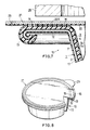
- Figs. 7 and 8 show another embodiment, i.e., a food packaging container 10 having a curled edge 13. at the outer end of a flange 12.
- the flange 12 is formed, in a first thermoplastic resin layer 3a on the surface side of a thermoplastic resin layer 3, with an incision and an annular incision 16 each of V-shaped cross section which are positioned close to the opening-defining inner periphery of the body of the container and close to the curled edge 13, respectively, the incisions extending along the entire circumference of the flange 12.
- thermoplastic resin layer 3 of the flange 12 between the incisions 15, 16 is fused the corresponding portion 22A of a heat-sealing material layer 22 on the lower side of a lid 21 by the heat-pressing member 25 of a heat-sealing device.
- the incisions 15, 16 are formed, for example, by partly cutting the first layer 4 with a blade or partly removing the first layer with heat.
- the distance between the two incisions 15, 16 is dependent on the width of heat sealing by the heat-pressing member 25 of the heat-sealing device. A satisfactory result can be obtained insofar as the heat-sealing material layer portion 22A on the lower side of the lid 21 is fused to the resin layer 3 of the flange at the portion thereof between the two incisions 15 and 16.
- the food packaging container 10 shown in Fig. 9 is prepared from a laminate sheet 1 having a layer 3 of single thermoplastic resin (I).
- a laminate sheet 1 having a layer 3 of single thermoplastic resin (I) To render the lid easily peelable from the container 10, an aluminum foil layer 2 and the thermoplastic resin layer 3 of the laminate sheet 1 forming the container body 11 are separably joined to each other by a joint layer 5 of a polyether adhesive having an adherend releasing property.
- the joint layer 5 may be a usual adhesive layer of urethane, polyester or like adhesive, or may be formed by coating one surface of an adhesive layer of monoolefin-unsaturated carboxylic acid copolymer resin or metal salt thereof, for example, with a silicone resin coating composition assuring ease of peeling.
- the peel strength between the aluminum foil layer 2 and the thermoplastic resin layer 3 of the laminate sheet 1 is 500 to 1500 g/15 mm width, preferably 700 to 900 g/15 mm width.
- the adhesive strength between the inside thermoplastic resin layer 3 of the container body 11 and the aluminum foil layer 2 thereof is made smaller than the adhesive strength between the resin layer 3 and the heat-sealing material layer 22 of the lid 21 fused thereto.
- the flange 12 of the container 10 has a curled edge 13 at its outer end.
- the flange 12 is formed in the thermoplastic resin layer 3 with two incisions 15, 16 of V-shaped cross section extending generally along the entire circumference of the flange 12 and positioned close to the opening-defining inner periphery of the container body and close to the curled edge 13, respectively.
- To the portion of the thermoplastic resin layer 3 of the flange 12 between the incisions 15, 16 is fused the corresponding portion 22A of the heat-sealing material layer 22 on the lower side of the lid 21 by the heat-pressing member 25 of a heat-sealing device.
- the portion of the resin layer 3 of the flange 12 between the incisions 15, 16 is readily peeled, as bonded to the portion 22A of the heat-sealing layer of the lid 21, off the aluminum foil layer 2.
- the container 10 can be opened with great ease.
- the outer incision of the two incisions in the thermoplastic resin layer 3 of the flange 12 of the container body 11 may be formed in the curled edge 13 itself as seen in Figs. 10 to 12.
- thermoplastic resin layer 3 of the flange 12 comprises unstretched co-extruded thermoplastic resins.
- a peeling cutout portion 17 formed in the first resin layer 3a of the curled edge 13 itself extends outward obliquely downward from the curl starting end of the curled edge 13.
- the cutout portion 17 is formed approximately over the entire circumference of the curled edge 13.
- the peeling cutout portion 17 of Fig. 11 is slightly different from the one shown in Fig. 10 and is formed by cutting the first thermoplastic resin layer 3a of the curled edge 13 itself along a vertical plane tangent to the second thermoplastic resin layer 3b.
- the thermoplastic resin layer 3 has some bent portion left on the curled edge 13, so that the heat-pressing member 25 of the heat-sealing device is preferably shaped in conformity with the shape of the bent portion.
- the resin layer 3 of the flange 12 shown in Fig. 12 is made of a single thermoplastic resin.
- a peeling cutout portion 17 is formed in the resin layer 3 of the curled edge 13 itself and extends outward obliquely downward from the curl starting end of the curled edge 13, the cutout portion 17 being formed approximately over the entire circumference of the curled edge 13.
- a portion 22A of the heat-sealing material layer 22 on the lower side of the lid 21 is fused to the resin layer 3 over the portion thereof from the cutout portion 17 to the incision 15 by the heat-pressing member 25 of a heat sealing device so as to form a heat-sealed portion of required width.
- Fig. 12 is the same as the one shown in Fig. 9.
- the flange 12 of the food packaging container 10 may be formed with a bent edge 14 in place of the curled edge.
- the outer end portion of the flange 12 outward from an outer incision 16 is bent downward. This eliminates the likeli hood that the edge of the flange 12 will injure the hand of the person, while the presence of the bent edge 14 gives a sophisticated appearance to the container 10 and enhanced strength to the flange 12. Since the outer end portion of the flange 12 outward from the outer incision 16 is bent downward along the incision, the flange 12 is bendable with extreme ease, consequently making the container easy to manufacture.
- the bent edge 14 may be shaped otherwise, e.g., generally L-shaped in cross section. With the exception of the above feature, the embodiment of Fig. 13 is similar to the one shown in Fig. 7.
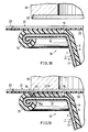
- Figs. 14 to 19 illustrate cases wherein an incision is formed in the flange 12 of the food packaging container 10 simultaneously when the heat-sealing material layer 22 of the lid 21 and the thermoplastic resin layer 3 of the flange 12 are heat-sealed.
- the container 10 shown in Figs. 14 and 15 is of the type wherein the flange 12 has no curled edge.
- the resin layer 3 of the container body 11 comprises unstretched co-extruded thermoplastic resins (II).
- the heat-pressing member 25 of a heat-sealing device is provided along the inner periphery of lower surface thereof with an annular projection (notch blade) 26 projecting downward (see Fig. 14).
- the lid 21 having the heat-sealing material layer 22 on its lower side is placed over the opening and flange 21 of the body 11.
- the heat-pressing member 25 is pressed against the peripheral portion of the lid 21 and the flange 12 to fuse the portion 22A of the heat-sealing material layer 22 and the portion of rhe thermoplastic resin layer 3a beneath the portion 22A, whereby a cutting groove (incision) 18 is formed in the first resin layer 3a with the annular projection 26 at the inner periphery of the heat-pressing member 25 at the same time.
- the container is heat-sealed and the groove 18 is formed by a single step (see Fig. 15).
- the first thermoplastic resin layer 3a is made, for example, of high-density polyethylene having a melting point of 120° C
- the second thermoplastic resin layer 3b is made of polypropylene having a melting point of 165°C
- the sealing material layer 22 of the lid 21 is formed of polyethylene having a melting point of 120° C like the layer 3a. Accordingly, when the heat-pressing member 25 maintained at a temperature of about 120° C is pressed against the first resin layer 3a and the heat-sealing material layer portion 22A, the two layers are fused, and at the same time, the annular projection 26 at the inner periphery of the heat-pressing member 25 melts the portion of the resin layer 3 opposed thereto to form the cutting groove (incision) 18.
- thermoplastic resins for forming the two resin layers 3a, 3b of the laminate sheet 1 are not limited to the above combination, the thermoplastic resin to be used for the first layer 3a usually has a lower melting point than the thermoplastic resin for the second layer 3b.
- the food packaging container 10 shown in Figs. 16 and 17 has two incisions formed in the flange 12 having a curled edge 13. The outer incision is formed simultaneously when the heat-sealing material layer 22 of the lid 22 and the thermoplastic resin layer 3 of the flange 12 are heat-sealed.
- the resin layer 3 of the laminate 1 forming the container body 11 comprises unstretched co-extruded thermoplastic resins (II).
- the curled edge 13 is formed at the outer end of the flange 12 of the container body 11.
- the flange 12 has the incision 15 already formed in the first resin layer 3a at a position close to the opening-defining inner periphery of the body 11 and extending generally along the entire circumference of the flange 12.
- the heat-pressing member 25 of a heat-sealing device has an annular projection 26 downwardly projecting from the outer periphery of its lower surface (see Fig. 16).
- a cutting groove (incision) 18 is formed in the first thermosplastic resin layer 3a at the same time with the annular protection 26 of the member 25 (see Fig. 17).
- thermoplastic resin layer 3 of the illustrated container body 11 is in the form of a single layer.
- the flange 12 of the container body 11 has a curled edge 13 at its outer end.
- the flange 12 has an inner incision 15 formed in advance at a position close to the opening periphery of the body 11 and extending approximately along the entire circumference of the flange 12.
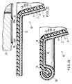
- the heat-pressing member 25 of a heat-sealing device has an annular projection (notch blade) 26 projecting downward from the outer periphery of its lower surface (see Fig. 18).
- a cutting groove (incision) 18 is formed in the thermoplastic resin layer 3 at the same time with the annular projection 26 of the heat-pressing member (see Fig. 19).
- the illustrated groove 18 has a thin bottom wall 18a, the wall 18a may be cut by the pressure of the annular projection 26 of the heat-pressing member 25.
- the method of sealing the food packaging container 10 illustrated in Figs. 14 to 19 is adapted to fuse the heat-sealing material layer 22 of the lid 21 to the thermoplastic resin layer 3 of the container body 11 and, at the same time, to form the cutting groove 18 (incision) in the flange 12. Accordingly, the container can be manufactured by a reduced number of steps at a very low equipment cost.
- the lid can be easily peeled off the container body after sealing without necessitating a great force for opening the container. The container is therefore very convenient to handle.
- Figs. 20 to 23 show a food packaging container wherein the flange 12 is formed with an outwardly or reversely curled edge 13.
- the body 11 of the container having the flange 12 along the opening periphery thereof is prepared from a laminate sheet 1 which comprises an aluminum foil layer 2, a layer 3 of unstretched co-extruded thermoplastic resins (II) joined to one surface of the foil layer 2 with an adhesive layer 4, and a synthetic resin protective covering layer 7 joined to the other surface of the aluminum foil layer 2 with an adhesive layer 8 and not fusible to a heat- sealing material layer 22 of a lid 21.
- a laminate sheet 1 which comprises an aluminum foil layer 2, a layer 3 of unstretched co-extruded thermoplastic resins (II) joined to one surface of the foil layer 2 with an adhesive layer 4, and a synthetic resin protective covering layer 7 joined to the other surface of the aluminum foil layer 2 with an adhesive layer 8 and not fusible to a heat- sealing material layer 22 of a lid 21.
- the reversely curled ege 13 of the flange 12 of the container body 11 has on the inner side thereof the first thermoplastic resin layer 3a to be fused to the heat-sealing material layer 22 of the lid 21, and the non-fusible protective covering layer 7 on the outer side.
- the flange 12 is formed in the first resin layer 3a with incisions 15 and 16 positioned close to the opening-defining inner periphery of the container body and at the base portion of the curled edge 13, respectively, and extending approximately along the entire circumference of the flange 12.
- the adhesive strength of the innermost first resin layer 3a of the container body 11 and the second resin layer 3b is smaller than the adhesive strength between the heat-sealing material layer 22 of the lid 21 and the first resin layer 3a between the incisions 15, 16 at the fused portion.
- the two incisions 15, 16 are formed in the first resin layer 3a of the flange 12 by an incising device 27 having two downward annular projections (notch blades) 26a, 26b at the same time.
- the outer incision 16 at the base end of the curled edge 13 has a larger width than the inner incision 15. If the portion of the flange 12 outward from the outer incision 16 is reversely curled to form the edge 13 after the two incisions 15, 16 are formed, the inside first resin layer 3a will contract, greatly reducing the width of the outer incision 16 and possibly closing the incision. This situation is avoidable by initially giving an increased width to the outer incision 16.
- the reversely curled edge 13 of the flange 12 of the container body 11 is so formed that the first resin layer 3a to be fused to the heat-sealing material layer 22 of the lid 21 is positioned inside, with the non-fusible protective layer 7 positioned outside. Accordingly, the heat-sealing material layer 22 of the closure 21 is in contact with the layer 7 of the curled edge 13, with the result that even if the position of heating and pressing by the heat-pressing member 25 of a heat-sealing device somewhat shifts toward the curled edge 13, the sealing material layer 22 of the lid 21 will not be fused to the curled edge 13 outside the outer incision 16.
- the container can therefore be heat-sealed properly, while the lid can be easily peeled off to open the container without necessitating a great force.
- the container is very convenient to handle.
- Figs. 24 and 25 show another food packaging container 10 wherein the flange 12 similarly has a reversely curled edge 13 and is provided with an outer incision 16 close to the edge 13. Accordingly, it is likely that the heat-sealing material layer 22 will be fused to the first thermoplastic resin layer 3a outside the outer incision 16 owing to a shift in the position of heating and pressing by the heat-pressing member 25 for heat sealing. To preclude this, a fusion preventing layer 19 is provided on the surface of the first resin layer 3a of the flange 12 between the outer incision 12 and the curled edge 13.
- Examples of materials useful for forming the fusion preventing layer 19 are polyamide resin, polyester resin, polyamide-nitrocellulose copolymer, silicone resin-nitrocellulose copolymer, silicone resin, urethane resin, aminoalkyd resin, wax and the like.
- the layer 19 is about 1 to about 5 ⁇ m in thickness.
- the layer 19 is provided, for example, by coating or affixing.
- the container With the fusion preventing layer 19 provided, the container can be heat-sealed properly, while the lid can be peeled off easily without necessitating a great force to open the container 10 in a stable manner.
- the food packaging container 10 is therefore very convenient to handle.
- the fusion preventing layer 19 may be formed on the heat-sealing material layer 22 of the lid 21.
- Each of the food packaging container 10 to be formed included a container body 11 having a flange 12 around an opening-defining peripheral edge and prepared from a laminate sheet 1 comprising an aluminum foil layer 2 120 ⁇ m in thickness, and a thermoplastic resin layer 3 300 ⁇ m in thickness and joined to one surface of the foil layer 2 with an adhesive layer 4, by deep-drawing the laminate sheet 1 with the resin layer 3 inside.
- the flange 12 was formed with a curled edge 13 at its outer end.
- thermoplastic resin layer 3 was made of a single thermoplastic resin.
- the resin layer 3 was made of unstretched co-extruded thermoplastic resins.
- the circular blank cut out from the laminate sheet 1 and to be deep-drawn was 115 mm in diameter.
- the container body 11 shaped was 70 mm in opening diameter and 30 mm in depth. Accordingly, the drawing ratio of the container body 11, i.e., the depth/opening diameter (H/W) ratio, was 3/7.
- the result is represeted by ⁇ , and if the flange 12 wrinkled, the result is represented by X.
- the material which was free of fracture is represented by ⁇ , and the material fractured by X.
- the material which was uniformly curled at the outer end of the flange 12 is represented by ⁇ . If otherwise, the result is represented by X.
- the material which developed a fracture due to drawing was not tested for curling and is represented by - .
- the table also shows the mechanical properties thereof, i.e., tensile strength ⁇ B (kgf/mm2), proof stress ⁇ 0.2 (kgf/mm2), elongation ⁇ (%) and percent earing (%).
- thermoplastic resin layers 3 are the mechanical properties thereof, i.e., the machine direction (MD) to transverse direction (TD) ratio of modulus of elasticity in tension, the MD/TD ratio of elongation, and the MD/TD ratio of breaking strength.
- MD machine direction
- TD transverse direction
- breaking strength i.e., the MD/TD ratio of modulus of elasticity in tension
- MD/TD ratio of elongation the MD/TD ratio of breaking strength.
- Aluminum foil Example No. Kind Thickness ( ⁇ m) Tensile strength Proof stress ⁇ 0.2 Elongation (%) Earing (%)
Landscapes
- Physics & Mathematics (AREA)
- Thermal Sciences (AREA)
- Engineering & Computer Science (AREA)
- Mechanical Engineering (AREA)
- Packages (AREA)
- Laminated Bodies (AREA)
- General Preparation And Processing Of Foods (AREA)
- Containers Having Bodies Formed In One Piece (AREA)
Applications Claiming Priority (2)
| Application Number | Priority Date | Filing Date | Title |
|---|---|---|---|
| JP226482/89 | 1989-08-31 | ||
| JP1226482A JPH02167740A (ja) | 1988-08-31 | 1989-08-31 | 食品包装容器用積層シート |
Publications (3)
| Publication Number | Publication Date |
|---|---|
| EP0417380A2 true EP0417380A2 (de) | 1991-03-20 |
| EP0417380A3 EP0417380A3 (en) | 1991-10-23 |
| EP0417380B1 EP0417380B1 (de) | 1996-03-27 |
Family
ID=16845794
Family Applications (1)
| Application Number | Title | Priority Date | Filing Date |
|---|---|---|---|
| EP90101316A Expired - Lifetime EP0417380B1 (de) | 1989-08-31 | 1990-01-23 | Behälter zum Verpacken von Lebensmitteln |
Country Status (8)
| Country | Link |
|---|---|
| US (1) | US5098751A (de) |
| EP (1) | EP0417380B1 (de) |
| KR (1) | KR950012784B1 (de) |
| AT (1) | ATE135965T1 (de) |
| AU (1) | AU628496B2 (de) |
| CA (1) | CA2007748C (de) |
| DE (1) | DE69026171T2 (de) |
| NZ (1) | NZ233001A (de) |
Cited By (7)
| Publication number | Priority date | Publication date | Assignee | Title |
|---|---|---|---|---|
| WO1996025292A1 (en) * | 1995-02-17 | 1996-08-22 | The Dow Chemical Company | Protective polymeric film for lamination to metal |
| EP1081051A1 (de) * | 1999-09-02 | 2001-03-07 | Sonoco Development, Inc. | Leicht zu öffnen der mehrlagiger Behälter mit einer Verschlussmembran |
| WO2004056672A1 (de) * | 2002-12-19 | 2004-07-08 | L. Nusser Gmbh | Verpackungsmaterial aus aluminium |
| EP1477408A1 (de) * | 2003-05-12 | 2004-11-17 | Sonoco Development, Inc. | Verbundbehälter mit Membrandeckel und Verbundbehälterkörper |
| EP1655130A1 (de) * | 2004-11-08 | 2006-05-10 | Alcan Technology & Management Ltd. | Kaltverformbares Laminat |
| EP1995054A1 (de) | 2007-05-24 | 2008-11-26 | Constantia Hueck Folien GmbH & Co. KG | Verpackungsmaterial |
| DE102007059189A1 (de) * | 2007-12-06 | 2009-06-10 | Wipak Walsrode Gmbh & Co. Kg | Wiederverschließbare Verpackung |
Families Citing this family (53)
| Publication number | Priority date | Publication date | Assignee | Title |
|---|---|---|---|---|
| US5199595A (en) * | 1990-04-26 | 1993-04-06 | Alusuisse-Lonza Services Ltd. | Method of producing a cup-shaped, sterilisable container, as well as container |
| US5465863A (en) * | 1993-03-10 | 1995-11-14 | Greif Bros. Corporation | Recyclable steel drum for hot flow products |
| JP2677172B2 (ja) * | 1993-10-14 | 1997-11-17 | 東洋製罐株式会社 | 保香性及び耐衝撃性に優れたラミネート絞り容器 |
| US6264098B1 (en) | 1997-02-06 | 2001-07-24 | Sonoco Development, Inc. | Tubular container with a heat seal having non-symmetrical inner and outer beads |
| US5979748A (en) * | 1997-02-06 | 1999-11-09 | Sonoco Development, Inc. | Tubular container with a heat seal having an inner and outer bead and method of manufacturing said container |
| JP3883652B2 (ja) | 1997-06-23 | 2007-02-21 | 大日本印刷株式会社 | 板状枠体付きicキャリアとその製造方法 |
| JP4522562B2 (ja) * | 1999-09-20 | 2010-08-11 | 大日本印刷株式会社 | 包装材料および容器 |
| US6234386B1 (en) | 1999-10-11 | 2001-05-22 | Sonoco Development, Inc. | Container with heat seal surface having a substantially planar portion |
| US6544613B1 (en) | 1999-11-08 | 2003-04-08 | Sonoco Development, Inc. | Composite container and method of heat sealing composite containers |
| WO2002038462A2 (en) * | 2000-11-13 | 2002-05-16 | The Procter & Gamble Company | Removable closure device |
| CN1214391C (zh) * | 2001-04-23 | 2005-08-10 | 日东电工株式会社 | 用于硬盘驱动器的压敏粘性标签 |
| US20030014947A1 (en) * | 2001-07-19 | 2003-01-23 | Sarojini Deevi | Laminated metal foil packaging material and method of making |
| JP4133436B2 (ja) * | 2003-02-26 | 2008-08-13 | 出光ユニテック株式会社 | 易開封性包装体および易開封性包装体の製造方法 |
| JP4146267B2 (ja) * | 2003-04-08 | 2008-09-10 | 出光ユニテック株式会社 | 容器、包装体及び容器の製造方法 |
| US20040253401A1 (en) * | 2003-06-12 | 2004-12-16 | Pratt Steven Duane | Housing including integrated indicia and method of making |
| GB0515357D0 (en) * | 2005-07-27 | 2005-08-31 | Psimedica Ltd | Silicon package material |
| PL1878666T3 (pl) * | 2006-07-13 | 2011-03-31 | Impress Metal Packaging Sa | Pokrywa do pojemnika wyposażona w zdzieralną membranę |
| DE102007031196A1 (de) * | 2007-07-04 | 2009-01-08 | Berwing, Benjamin | Nahrungsergänzungsmittel und Verfahren zur Herstellung eines mineralisierten kohlensäurenhaltigen Tafelwassers |
| BRPI1008943A2 (pt) * | 2009-03-13 | 2016-03-15 | Nestec Sa | coberturas compósitas para recipientes |
| US9469445B2 (en) | 2011-02-07 | 2016-10-18 | Berry Plastics Corporation | Package with lid sealing system |
| USD675929S1 (en) * | 2011-04-06 | 2013-02-12 | Cj Cheiljedang Corp. | Container for food packaging |
| US9032698B2 (en) | 2011-07-07 | 2015-05-19 | Berry Plastics Corporation | Package with lid sealing system |
| USD673054S1 (en) * | 2011-08-16 | 2012-12-25 | Cj Cheiljedang Corp. | Container for food packing |
| US9114925B2 (en) | 2011-09-13 | 2015-08-25 | Lincoln Global, Inc. | Container for elongated articles |
| US9096347B2 (en) | 2012-03-20 | 2015-08-04 | Berry Plastics Corporation | Stand-up Package |
| US9145251B2 (en) | 2012-10-26 | 2015-09-29 | Berry Plastics Corporation | Package |
| MX2015015310A (es) | 2013-05-03 | 2016-08-23 | Berry Plastics Corp | Cierre de contenedor. |
| RU2647791C2 (ru) | 2013-05-17 | 2018-03-19 | Конинклейке Дауве Эгбертс Б.В. | Система для приготовления напитка, капсула и способ приготовления напитка |
| GB201308927D0 (en) | 2013-05-17 | 2013-07-03 | Kraft Foods R & D Inc | A beverage preparation system, a capsule and a method for forming a beverage |
| US9630762B2 (en) * | 2014-01-22 | 2017-04-25 | Berry Plastics Corporation | Package with peelable closure |
| JP6626258B2 (ja) * | 2014-04-07 | 2019-12-25 | 昭和電工パッケージング株式会社 | ラミネート外装材の製造方法 |
| WO2016014825A1 (en) | 2014-07-23 | 2016-01-28 | Berry Plastics Corporation | Package with peelable closure |
| US10449594B2 (en) * | 2014-11-12 | 2019-10-22 | EKL Machine Company | Flange projection control system and method |
| GB201420262D0 (en) | 2014-11-14 | 2014-12-31 | Kraft Foods R & D Inc | A method of forming a cup-shaped body for a beverage capsule |
| US10532872B2 (en) | 2014-12-08 | 2020-01-14 | Berry Plastics Corporation | Package |
| DE102015205221A1 (de) * | 2015-03-23 | 2016-09-29 | Multivac Sepp Haggenmüller Se & Co. Kg | Tiefziehverpackungsmaschine, Verfahren und Verpackung |
| JP6828680B2 (ja) * | 2015-03-27 | 2021-02-10 | 大日本印刷株式会社 | 電池用包装材料、その製造方法及び電池 |
| ES2848175T3 (es) | 2015-08-31 | 2021-08-05 | Converter Mfg Llc | Artículo termoplástico conformado con bordes lisos |
| JP7210277B2 (ja) | 2015-09-15 | 2023-01-23 | ジースリー・エンタープライゼズ・インコーポレイテッド | 金属に適用される代替コーティングのための装置及び方法 |
| EP3266606A1 (de) * | 2016-07-04 | 2018-01-10 | Amcor Flexibles Rorschach AG | Tiefziehfähige folie |
| EP3589475B1 (de) * | 2017-02-28 | 2025-06-25 | Converter Manufacturing, LLC | Geformter thermoplastischer artikel mit glatten kanten und optionaler abziehbarer oberfläche |
| USD829106S1 (en) * | 2017-06-20 | 2018-09-25 | Cj Cheiljedang Corp. | Container for food packaging |
| JP7039965B2 (ja) * | 2017-11-29 | 2022-03-23 | 東洋製罐株式会社 | 金属製容器製品の製造方法 |
| JP7039966B2 (ja) * | 2017-11-29 | 2022-03-23 | 東洋製罐株式会社 | 金属製容器本体および金属製容器製品 |
| JP7381255B2 (ja) * | 2018-09-27 | 2023-11-15 | 株式会社レゾナック・パッケージング | 成形容器およびその製造方法 |
| WO2020106895A1 (en) | 2018-11-20 | 2020-05-28 | G3 Enterprises, Inc. | Apparatus and methods using coatings for metal applications |
| DE102019112034A1 (de) * | 2019-05-08 | 2020-11-12 | Constantia Pirk Gmbh & Co. Kg | Abdeckfolie, insbesondere für Lebensmittelkapseln |
| EP3993989B1 (de) | 2019-07-03 | 2026-04-01 | Lgab Llc | Zellstoffbehälter mit schmelzverbindung und verfahren zu dessen herstellung |
| JP7613859B2 (ja) * | 2019-10-09 | 2025-01-15 | 株式会社レゾナック・パッケージング | 油脂含有食品収容用の成形容器及び包装体 |
| CN112644126B (zh) * | 2019-10-09 | 2023-12-05 | 株式会社力森诺科包装 | 含油脂食品收纳用的成型容器及包装体 |
| EP4261040A4 (de) * | 2020-12-11 | 2024-09-18 | National Institute for Materials Science | Laminat und verpackungskörper oder behälter |
| USD1004417S1 (en) * | 2022-07-01 | 2023-11-14 | Cj Cheiljedang Corporation | Container for food packing |
| US12258172B1 (en) | 2024-02-20 | 2025-03-25 | Michael R. Borse | Tray for use with overwrapping |
Family Cites Families (6)
| Publication number | Priority date | Publication date | Assignee | Title |
|---|---|---|---|---|
| DE1922678A1 (de) * | 1969-05-03 | 1970-11-05 | Hueck & Bueren Kg | Leicht zu oeffnender Verpackungsbehaelter |
| SE446703B (sv) * | 1982-01-20 | 1986-10-06 | Tetra Pak Finance & Trading | Sett att framstella ett for djupdragning eller streckning lempat laminatmaterial, genom settet framstellt laminat samt av laminatet tillverkad artikel |
| US4734303A (en) * | 1985-07-19 | 1988-03-29 | Toyo Seikan Kaisha, Ltd. | Deep-draw-formed vessel and process for preparation thereof |
| CA1303522C (en) * | 1986-04-08 | 1992-06-16 | Takanori Suzuki | Easily-openable packaging container |
| GB8724242D0 (en) * | 1987-10-15 | 1987-11-18 | Metal Box Plc | Laminated metal sheet |
| US4875597A (en) * | 1988-12-02 | 1989-10-24 | Weirton Steel Corporation | Convenience packaging |
-
1990
- 1990-01-15 CA CA002007748A patent/CA2007748C/en not_active Expired - Fee Related
- 1990-01-19 US US07/467,245 patent/US5098751A/en not_active Expired - Fee Related
- 1990-01-22 KR KR1019900000722A patent/KR950012784B1/ko not_active Expired - Fee Related
- 1990-01-23 AT AT90101316T patent/ATE135965T1/de not_active IP Right Cessation
- 1990-01-23 DE DE69026171T patent/DE69026171T2/de not_active Expired - Fee Related
- 1990-01-23 EP EP90101316A patent/EP0417380B1/de not_active Expired - Lifetime
- 1990-03-20 AU AU52014/90A patent/AU628496B2/en not_active Ceased
- 1990-03-20 NZ NZ233001A patent/NZ233001A/xx unknown
Cited By (10)
| Publication number | Priority date | Publication date | Assignee | Title |
|---|---|---|---|---|
| WO1996025292A1 (en) * | 1995-02-17 | 1996-08-22 | The Dow Chemical Company | Protective polymeric film for lamination to metal |
| EP1081051A1 (de) * | 1999-09-02 | 2001-03-07 | Sonoco Development, Inc. | Leicht zu öffnen der mehrlagiger Behälter mit einer Verschlussmembran |
| WO2004056672A1 (de) * | 2002-12-19 | 2004-07-08 | L. Nusser Gmbh | Verpackungsmaterial aus aluminium |
| EP1477408A1 (de) * | 2003-05-12 | 2004-11-17 | Sonoco Development, Inc. | Verbundbehälter mit Membrandeckel und Verbundbehälterkörper |
| US6857561B2 (en) | 2003-05-12 | 2005-02-22 | Sonoco Development, Inc. | Composite container with membrane and bead closure system |
| EP1655130A1 (de) * | 2004-11-08 | 2006-05-10 | Alcan Technology & Management Ltd. | Kaltverformbares Laminat |
| EP1995054A1 (de) | 2007-05-24 | 2008-11-26 | Constantia Hueck Folien GmbH & Co. KG | Verpackungsmaterial |
| WO2008141808A1 (de) * | 2007-05-24 | 2008-11-27 | Constantia Hueck Folien Gmbh & Co. Kg | Verpackungsmaterial |
| RU2464174C2 (ru) * | 2007-05-24 | 2012-10-20 | Константия Хуек Фолиен Гмбх Унд Ко. Кг | Упаковочный материал |
| DE102007059189A1 (de) * | 2007-12-06 | 2009-06-10 | Wipak Walsrode Gmbh & Co. Kg | Wiederverschließbare Verpackung |
Also Published As
| Publication number | Publication date |
|---|---|
| DE69026171T2 (de) | 1996-11-07 |
| CA2007748A1 (en) | 1991-02-28 |
| ATE135965T1 (de) | 1996-04-15 |
| AU5201490A (en) | 1991-03-07 |
| EP0417380A3 (en) | 1991-10-23 |
| KR910004431A (ko) | 1991-03-28 |
| DE69026171D1 (de) | 1996-05-02 |
| US5098751A (en) | 1992-03-24 |
| KR950012784B1 (ko) | 1995-10-21 |
| NZ233001A (en) | 1993-02-25 |
| CA2007748C (en) | 1996-01-02 |
| AU628496B2 (en) | 1992-09-17 |
| EP0417380B1 (de) | 1996-03-27 |
Similar Documents
| Publication | Publication Date | Title |
|---|---|---|
| EP0417380B1 (de) | Behälter zum Verpacken von Lebensmitteln | |
| CA1325189C (en) | Easy-open lid | |
| CN100500523C (zh) | 易开封性包装体 | |
| US4905838A (en) | Easily-openable packaging container having notched inner surface layer | |
| EP0461640B1 (de) | Leicht zu öffnender Behälter und Verfahren zu seiner Herstellung | |
| US5178293A (en) | Easily-openable packaging container | |
| US4781323A (en) | Reclosable closure assembly for container | |
| US5024044A (en) | Process for producing an easily opened package | |
| JPS63312837A (ja) | 容易に開封可能な包装品用積層品 | |
| CA1200514A (en) | Container closure system with vent opening through the closure tape | |
| USRE33893E (en) | Reclosable closure assembly for container | |
| EP0214791B1 (de) | Wiederverschliessbare Verschlussvorrichtung für einen Behälter | |
| JPH02167740A (ja) | 食品包装容器用積層シート | |
| JPH0314476A (ja) | 食品包装用易開封容器 | |
| JPH0647772Y2 (ja) | 食品包装用アルミニウム箔樹脂積層容器 | |
| JP2925652B2 (ja) | 食品包装体 | |
| JP3768548B2 (ja) | カップ容器 | |
| JP2994864B2 (ja) | 易開封性密封容器 | |
| JPH03240667A (ja) | 包装体の製造方法 | |
| JP3966584B2 (ja) | 熱封緘蓋材及び容器 | |
| JPH0567511B2 (de) | ||
| JPH03111269A (ja) | 食品包装用容器 | |
| JP2984464B2 (ja) | 易開封性密封容器 | |
| JP2004106858A (ja) | 食品容器用蓋材 | |
| JP3745022B2 (ja) | 易開封性容器 |
Legal Events
| Date | Code | Title | Description |
|---|---|---|---|
| PUAI | Public reference made under article 153(3) epc to a published international application that has entered the european phase |
Free format text: ORIGINAL CODE: 0009012 |
|
| AK | Designated contracting states |
Kind code of ref document: A2 Designated state(s): AT BE CH DE FR GB IT LI NL SE |
|
| PUAL | Search report despatched |
Free format text: ORIGINAL CODE: 0009013 |
|
| AK | Designated contracting states |
Kind code of ref document: A3 Designated state(s): AT BE CH DE FR GB IT LI NL SE |
|
| 17P | Request for examination filed |
Effective date: 19920319 |
|
| 17Q | First examination report despatched |
Effective date: 19940613 |
|
| GRAH | Despatch of communication of intention to grant a patent |
Free format text: ORIGINAL CODE: EPIDOS IGRA |
|
| GRAA | (expected) grant |
Free format text: ORIGINAL CODE: 0009210 |
|
| AK | Designated contracting states |
Kind code of ref document: B1 Designated state(s): AT BE CH DE FR GB IT LI NL SE |
|
| REF | Corresponds to: |
Ref document number: 135965 Country of ref document: AT Date of ref document: 19960415 Kind code of ref document: T |
|
| REF | Corresponds to: |
Ref document number: 69026171 Country of ref document: DE Date of ref document: 19960502 |
|
| ITF | It: translation for a ep patent filed | ||
| ET | Fr: translation filed | ||
| PLBE | No opposition filed within time limit |
Free format text: ORIGINAL CODE: 0009261 |
|
| STAA | Information on the status of an ep patent application or granted ep patent |
Free format text: STATUS: NO OPPOSITION FILED WITHIN TIME LIMIT |
|
| 26N | No opposition filed | ||
| PGFP | Annual fee paid to national office [announced via postgrant information from national office to epo] |
Ref country code: BE Payment date: 19991203 Year of fee payment: 11 |
|
| PGFP | Annual fee paid to national office [announced via postgrant information from national office to epo] |
Ref country code: SE Payment date: 19991213 Year of fee payment: 11 |
|
| PGFP | Annual fee paid to national office [announced via postgrant information from national office to epo] |
Ref country code: AT Payment date: 20000112 Year of fee payment: 11 |
|
| PGFP | Annual fee paid to national office [announced via postgrant information from national office to epo] |
Ref country code: NL Payment date: 20000131 Year of fee payment: 11 |
|
| PG25 | Lapsed in a contracting state [announced via postgrant information from national office to epo] |
Ref country code: AT Free format text: LAPSE BECAUSE OF NON-PAYMENT OF DUE FEES Effective date: 20010123 |
|
| PG25 | Lapsed in a contracting state [announced via postgrant information from national office to epo] |
Ref country code: SE Free format text: LAPSE BECAUSE OF NON-PAYMENT OF DUE FEES Effective date: 20010124 |
|
| PG25 | Lapsed in a contracting state [announced via postgrant information from national office to epo] |
Ref country code: BE Free format text: LAPSE BECAUSE OF NON-PAYMENT OF DUE FEES Effective date: 20010131 |
|
| BERE | Be: lapsed |
Owner name: SHOWA ALUMINUM CORP. Effective date: 20010131 Owner name: IDEMITSU PETROCHEMICAL CO. LTD Effective date: 20010131 |
|
| PG25 | Lapsed in a contracting state [announced via postgrant information from national office to epo] |
Ref country code: NL Free format text: LAPSE BECAUSE OF NON-PAYMENT OF DUE FEES Effective date: 20010801 |
|
| EUG | Se: european patent has lapsed |
Ref document number: 90101316.9 |
|
| NLV4 | Nl: lapsed or anulled due to non-payment of the annual fee |
Effective date: 20010801 |
|
| REG | Reference to a national code |
Ref country code: GB Ref legal event code: 732E |
|
| REG | Reference to a national code |
Ref country code: GB Ref legal event code: IF02 |
|
| REG | Reference to a national code |
Ref country code: FR Ref legal event code: TQ |
|
| REG | Reference to a national code |
Ref country code: CH Ref legal event code: PFA Free format text: IDEMITSU PETROCHEMICAL CO. LTD.;SHOWA ALUMINUM CORPORATION TRANSFER- IDEMITSU PETROCHEMICAL CO. LTD.;SHOWA DENKO K.K. |
|
| PGFP | Annual fee paid to national office [announced via postgrant information from national office to epo] |
Ref country code: CH Payment date: 20030123 Year of fee payment: 14 |
|
| PGFP | Annual fee paid to national office [announced via postgrant information from national office to epo] |
Ref country code: GB Payment date: 20040108 Year of fee payment: 15 |
|
| PGFP | Annual fee paid to national office [announced via postgrant information from national office to epo] |
Ref country code: FR Payment date: 20040119 Year of fee payment: 15 |
|
| PG25 | Lapsed in a contracting state [announced via postgrant information from national office to epo] |
Ref country code: LI Free format text: LAPSE BECAUSE OF NON-PAYMENT OF DUE FEES Effective date: 20040131 Ref country code: CH Free format text: LAPSE BECAUSE OF NON-PAYMENT OF DUE FEES Effective date: 20040131 |
|
| PGFP | Annual fee paid to national office [announced via postgrant information from national office to epo] |
Ref country code: DE Payment date: 20040322 Year of fee payment: 15 |
|
| REG | Reference to a national code |
Ref country code: CH Ref legal event code: PL |
|
| PG25 | Lapsed in a contracting state [announced via postgrant information from national office to epo] |
Ref country code: IT Free format text: LAPSE BECAUSE OF NON-PAYMENT OF DUE FEES Effective date: 20050123 Ref country code: GB Free format text: LAPSE BECAUSE OF NON-PAYMENT OF DUE FEES Effective date: 20050123 |
|
| PG25 | Lapsed in a contracting state [announced via postgrant information from national office to epo] |
Ref country code: DE Free format text: LAPSE BECAUSE OF NON-PAYMENT OF DUE FEES Effective date: 20050802 |
|
| REG | Reference to a national code |
Ref country code: FR Ref legal event code: TQ |
|
| GBPC | Gb: european patent ceased through non-payment of renewal fee |
Effective date: 20050123 |
|
| PG25 | Lapsed in a contracting state [announced via postgrant information from national office to epo] |
Ref country code: FR Free format text: LAPSE BECAUSE OF NON-PAYMENT OF DUE FEES Effective date: 20050930 |
|
| REG | Reference to a national code |
Ref country code: FR Ref legal event code: ST |