EP0417423A2 - Circuit pour la détection de la vitesse de rotation d'une roue - Google Patents
Circuit pour la détection de la vitesse de rotation d'une roue Download PDFInfo
- Publication number
- EP0417423A2 EP0417423A2 EP90113395A EP90113395A EP0417423A2 EP 0417423 A2 EP0417423 A2 EP 0417423A2 EP 90113395 A EP90113395 A EP 90113395A EP 90113395 A EP90113395 A EP 90113395A EP 0417423 A2 EP0417423 A2 EP 0417423A2
- Authority
- EP
- European Patent Office
- Prior art keywords
- wheel
- output
- speed
- circuit according
- circuit
- Prior art date
- Legal status (The legal status is an assumption and is not a legal conclusion. Google has not performed a legal analysis and makes no representation as to the accuracy of the status listed.)
- Withdrawn
Links
Images
Classifications
-
- G—PHYSICS
- G01—MEASURING; TESTING
- G01P—MEASURING LINEAR OR ANGULAR SPEED, ACCELERATION, DECELERATION, OR SHOCK; INDICATING PRESENCE, ABSENCE, OR DIRECTION, OF MOVEMENT
- G01P21/00—Testing or calibrating of apparatus or devices covered by the preceding groups
- G01P21/02—Testing or calibrating of apparatus or devices covered by the preceding groups of speedometers
-
- G—PHYSICS
- G01—MEASURING; TESTING
- G01P—MEASURING LINEAR OR ANGULAR SPEED, ACCELERATION, DECELERATION, OR SHOCK; INDICATING PRESENCE, ABSENCE, OR DIRECTION, OF MOVEMENT
- G01P3/00—Measuring linear or angular speed; Measuring differences of linear or angular speeds
- G01P3/42—Devices characterised by the use of electric or magnetic means
- G01P3/44—Devices characterised by the use of electric or magnetic means for measuring angular speed
- G01P3/48—Devices characterised by the use of electric or magnetic means for measuring angular speed by measuring frequency of generated current or voltage
- G01P3/481—Devices characterised by the use of electric or magnetic means for measuring angular speed by measuring frequency of generated current or voltage of pulse signals
- G01P3/488—Devices characterised by the use of electric or magnetic means for measuring angular speed by measuring frequency of generated current or voltage of pulse signals delivered by variable reluctance detectors
Definitions
- the invention relates to a circuit for determining the speed of a wheel with an inductive sensor, the output of which is connected to a pulse shaping device, the output of which is connected to an evaluation device.
- inductive sensors In motor vehicles, it may be necessary, for example for an anti-lock braking system, to record the wheel speed or the speed of a wheel.
- inductive sensors are used, in which a periodically changing magnetic conductance, for example a ring gear arranged concentrically to the wheel and rotating synchronously with the wheel, induces a sine-like voltage, the frequency of which is proportional to the speed of the wheel.
- the approximately sinusoidal voltage is further processed by downstream electronics, which result from the voltage Rectangular pulses generated. From the time interval between certain sizes of the square-wave pulses, for example the rising edges, a statement about the speed of the wheel in question can be obtained with the aid of a digital processing device. Since the voltage generated in inductive sensors is proportional to the change in the magnetic field over time, the output voltage of an inductive sensor is very dependent on the frequency. The higher the frequency, the greater the amplitude of the output signal.
- the inductive sensors Since the inductive sensors have to be arranged directly on the wheel, they are increasingly exposed to environmental influences. They are polluted by street dirt and moisture and are subjected to high mechanical loads due to vibrations. The vibrations can, for example, change the distance of the encoder from the ring gear or lead to the breaking of an electrical line.
- the voltage generated by the inductive transmitter is generally not evaluated directly on the wheel, but in a central evaluation device to which the voltage is transmitted using electrical lines.
- the soiling can lead to so-called dirt resistances, which form a leakage current path between the two wires of a line.
- the dirt resistors make fault diagnosis difficult, which in some way evaluates the voltage drop across the ohmic internal resistance of the inductive sensor. This occurs when a direct current is impressed on the encoder. The voltage drop then considerably reduces the sensitivity of the pulse shaper circuit if the DC potential at the sensor is not decoupled from that at the pulse shaper device.
- the auxiliary device advantageously evaluates the amplitude of an output voltage present at the output of the inductive transmitter.
- the amplitude is a measure of the speed of the wheel. The higher the speed of the wheel, the greater the amplitude of the output voltage. Even if there is no linear relationship here, the evaluation of the amplitude is sufficient to influence the internal resistance and thus the sensitivity of the pulse shaping device sufficiently.
- the auxiliary device can also evaluate the frequency of the output voltage.
- the frequency is directly proportional to the speed.
- information can be drawn about possible dirt resistance and other currents, such as permanent changes in the air gap in the encoder.
- the auxiliary device advantageously changes an input resistance of the pulse shaping device.
- the easiest way to intervene in the internal resistance of the pulse shaping device is at the input.
- the remaining pulse shaping device can then be left unchanged.
- the pulse shaping device has a comparator connected as a Schmitt trigger and the input resistance influences the level of the voltage applied to the comparator.
- the auxiliary device has a switching element which, when a predetermined speed of the wheel is exceeded, connects a parallel resistor in parallel with the input resistance of the pulse shaping device. This results in a higher voltage drop across the ohmic internal resistance of the inductive encoder. The voltage applied to the comparator is thereby reduced. It is thus possible to check both the line to the inductive sensor for interruption and the correct function of the inductive sensor, for example the correct distance of the sensor from the ring gear, by connecting the parallel resistor.
- the switching element is advantageously designed as a transistor.
- the entire circuit can thus be carried out without mechanical elements.
- the auxiliary device has a microprocessor.
- the microprocessor can simultaneously be used to convert the pulses emitted by the pulse shaping device into the rotational speed of the wheel. Since information about the rotational speed of the wheel is thus already available, the microprocessor can also be used advantageously for controlling the switching element of the auxiliary device.
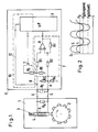
- a pulse generator 1 has a ring gear 2 which runs past a core 4 connected to a magnet 3 when a wheel (not shown) rotates.
- a coil 5 is wound around the core 4.
- the teeth of the ring gear 2 pass the core 4, the magnetic conductance of the magnetic circuit changes and thus the magnetic flux generated by the magnet 3 in the core 4.
- the change in the magnetic flux induces a current in the coil, which generates a voltage across a resistor R A.
- This voltage is fed to an evaluation device 11 via a two-wire line 6.
- dirt deposits on the surface so-called dirt deposits on the surface called “dirt resistance", that is, leakage current paths.
- Such dirt resistance is shown in dashed lines as resistance R S.
- the evaluation device 11 has a pulse shaper device 7, which turns the essentially sinusoidal output voltage of the inductive transmitter 1, which is supplied via the line 6 to the evaluation device 11, into a pulse train which is supplied to a microprocessor 9.
- the evaluation device 7 has a comparator 8 connected as a Schmitt trigger.
- the non-inverting input of the comparator 8 is connected via a resistor R2 to a potential P A formed by a voltage divider R3 / R4 at point A.
- the non-inverting input of the comparator 8 is connected to the output of the comparator via a resistor R7.
- the inverting input of the comparator 8 is connected via a resistor R1 to a potential P B , which changes essentially sinusoidally as a function of the voltage generated by the inductive transmitter 1 and of a resistor R6 (see FIG. 2).
- the potential P B is also supplied to the microprocessor 9 via a line 12. This evaluates the voltage at point B, for example determines the amplitude or frequency of the voltage. Both variables provide information about the number of revolutions of the ring gear 2 and thus about the number of revolutions of the wheel that is to be determined.
- a resistor R5 in parallel to the higher-resistance resistor R6. This reduces the internal resistance of the pulse shaping device and reduces its "sensitivity".
- Fig. 2 shows two voltages generated by the inductive transmitter 1, namely once the voltage 5, which at a fast wheel speed, i.e. a high number of revolutions is generated, and the voltage L, which at a slow wheel speed, i.e. a low revolution count of the wheel is generated. If the comparison voltage of the comparator 8 were left unchanged even at slow speeds, the comparator would no longer generate pulses at low speeds. On the other hand, if the low comparison voltage were to remain constant even at high wheel speeds, there would be no way to check whether the inductive transmitter 1 is still working correctly or is still connected.
Landscapes
- Physics & Mathematics (AREA)
- General Physics & Mathematics (AREA)
- Transmission And Conversion Of Sensor Element Output (AREA)
- Regulating Braking Force (AREA)
Applications Claiming Priority (2)
| Application Number | Priority Date | Filing Date | Title |
|---|---|---|---|
| DE3930895 | 1989-09-15 | ||
| DE3930895A DE3930895A1 (de) | 1989-09-15 | 1989-09-15 | Schaltung zur ermittlung der drehzahl eines rades |
Publications (2)
| Publication Number | Publication Date |
|---|---|
| EP0417423A2 true EP0417423A2 (fr) | 1991-03-20 |
| EP0417423A3 EP0417423A3 (en) | 1992-10-14 |
Family
ID=6389537
Family Applications (1)
| Application Number | Title | Priority Date | Filing Date |
|---|---|---|---|
| EP19900113395 Withdrawn EP0417423A3 (en) | 1989-09-15 | 1990-07-13 | Circuit for the determination of the rotational speed of a wheel |
Country Status (3)
| Country | Link |
|---|---|
| US (1) | US5101155A (fr) |
| EP (1) | EP0417423A3 (fr) |
| DE (1) | DE3930895A1 (fr) |
Cited By (6)
| Publication number | Priority date | Publication date | Assignee | Title |
|---|---|---|---|---|
| EP0569924A1 (fr) * | 1992-05-15 | 1993-11-18 | KNORR-BREMSE SYSTEME FÜR NUTZFAHRZEUGE GmbH | Procédé et dispositif de surveillance d'un capteur |
| EP0586942A1 (fr) * | 1992-09-10 | 1994-03-16 | Eaton Corporation | Circuit d'entrée pour capteur de vitesse de roue avec détection de l'état du capteur |
| FR2703493A1 (fr) * | 1993-04-01 | 1994-10-07 | Ricard Claude | Procédé et dispositif électronique, d'adaptation entre un capteur électronique de distance parcourue par un taxi ou par un camion, et le taximètre ou le chronotachygraphe associé à ce capteur. |
| FR2703492A1 (fr) * | 1993-04-01 | 1994-10-07 | Ricard Claude | Adaptateur électronique pour taximètre et procédé de calibrage de cet adaptateur. |
| ES2072189A2 (es) * | 1993-03-29 | 1995-07-01 | Interfacom S A | Sistema para el control de la medida del recorrido de vehiculos automoviles, aplicable en especial en taximetros, tacografos y cajas negras. |
| WO1995023975A3 (fr) * | 1994-02-28 | 1995-10-12 | Alliedsignal Truck Brake Syst | Detecteur de vitesse et circuit de conditionnement |
Families Citing this family (20)
| Publication number | Priority date | Publication date | Assignee | Title |
|---|---|---|---|---|
| EP0554267B1 (fr) * | 1990-10-24 | 1994-12-14 | ITT Automotive Europe GmbH | Procede et circuit de preparation du signal de sortie de capteur de vitesse de rotation |
| US5510707A (en) * | 1992-09-10 | 1996-04-23 | Eaton Corporation | Wheel speed sensor input circuit with sensor status detection employing a resistor biased compensator |
| JPH06102003A (ja) * | 1992-09-22 | 1994-04-12 | Fuji Koki Seisakusho:Kk | 磁性体移動検出装置 |
| US5459398A (en) * | 1993-12-17 | 1995-10-17 | Delco Electronics Corporation | Adaptive threshold circuit |
| US5450008A (en) * | 1994-02-22 | 1995-09-12 | Delco Electronics Corp. | Adaptive loading circuit for a differential input magnetic wheel speed sensor |
| US5812429A (en) * | 1994-06-23 | 1998-09-22 | Delco Electronics Corp. | Adaptive digital filter for automotive applications |
| DE19512613C2 (de) * | 1995-04-05 | 2001-01-18 | Bosch Gmbh Robert | Verfahren und Vorrichtung zur Regelung der Empfindlichkeit |
| JPH09178512A (ja) * | 1995-12-28 | 1997-07-11 | Mitsubishi Electric Corp | センサシステム及びセンサ |
| US5744950A (en) * | 1996-05-09 | 1998-04-28 | Ssi Technologies, Inc. | Apparatus for detecting the speed of a rotating element including signal conditioning to provide a fifty percent duty cycle |
| DE19954115C1 (de) | 1999-11-11 | 2001-04-05 | Bayerische Motoren Werke Ag | Eingangsschaltung für induktiven Drehzahlgeber |
| US6359430B1 (en) * | 1999-11-29 | 2002-03-19 | Delphi Technologies, Inc. | Vehicle speed sensor with molded shunt resistor |
| DE19961876A1 (de) | 1999-12-20 | 2001-06-28 | Micronas Gmbh | Verfahren zum Erfassen der Drehzahl und der Winkelstellung eines rotierenden Rades |
| US7262591B2 (en) * | 2000-12-20 | 2007-08-28 | Micronas Gmbh | Technique for sensing the rotational speed and angular position of a rotating wheel |
| DE10222205A1 (de) * | 2002-05-18 | 2003-11-27 | Bosch Gmbh Robert | Verfahren und Anordnung zur Erfassung der Bewegung eines Elements |
| DE10252031A1 (de) * | 2002-11-06 | 2004-05-27 | Micronas Gmbh | Vorrichtung und Verfahren zum Erfassen einer Winkelposition eines rotierenden Gegenstandes |
| DE102012201651A1 (de) * | 2012-02-03 | 2013-08-08 | Dr. Johannes Heidenhain Gmbh | Positionsmesseinrichtung |
| KR101394053B1 (ko) * | 2012-12-28 | 2014-05-09 | 현대자동차 주식회사 | 차속 검출 시스템 및 이를 이용한 차속 검출 방법 |
| GB201508015D0 (en) * | 2015-05-11 | 2015-06-24 | Airbus Operations Ltd | Tachometer systems and methods of determining the rotation speed of a wheel of a landing gear of an aircraft |
| CN110161284B (zh) * | 2019-06-11 | 2023-10-13 | 山东省计量科学研究院 | 机动车发动机转速测量仪校准装置 |
| DE102022102452A1 (de) | 2022-02-02 | 2023-08-03 | Knorr-Bremse Systeme für Nutzfahrzeuge GmbH | Auswerteschaltung und Verfahren zum Überwachen und Auslesen eines passiven Drehzahlsensors |
Family Cites Families (5)
| Publication number | Priority date | Publication date | Assignee | Title |
|---|---|---|---|---|
| AT31977B (de) * | 1905-12-06 | 1908-02-25 | Josef Seidener | Einrichtung zum Ausgleiche des Strombedarfes von mit Drehstrom betriebenen Arbeitsmaschinen. |
| JPS6239776A (ja) * | 1985-08-16 | 1987-02-20 | Nippon Denso Co Ltd | センサ断線検出装置 |
| DE3605995C2 (de) * | 1986-02-25 | 1996-11-14 | Teves Gmbh Alfred | Vorrichtung zur Messung der Winkelgeschwindigkeit eines rotierenden Körpers |
| FR2612645B1 (fr) * | 1987-03-20 | 1989-05-19 | Bendix France | Procede et dispositif de verification de l'etat de fonctionnement d'un capteur magnetique a reluctance variable et leur application en electronique automobile |
| FR2612713B1 (fr) * | 1987-03-20 | 1989-07-07 | Bendix Electronics Sa | Circuit convertisseur de signaux analogiques en signaux logiques |
-
1989
- 1989-09-15 DE DE3930895A patent/DE3930895A1/de not_active Withdrawn
-
1990
- 1990-07-13 EP EP19900113395 patent/EP0417423A3/de not_active Withdrawn
- 1990-09-14 US US07/583,379 patent/US5101155A/en not_active Expired - Fee Related
Cited By (6)
| Publication number | Priority date | Publication date | Assignee | Title |
|---|---|---|---|---|
| EP0569924A1 (fr) * | 1992-05-15 | 1993-11-18 | KNORR-BREMSE SYSTEME FÜR NUTZFAHRZEUGE GmbH | Procédé et dispositif de surveillance d'un capteur |
| EP0586942A1 (fr) * | 1992-09-10 | 1994-03-16 | Eaton Corporation | Circuit d'entrée pour capteur de vitesse de roue avec détection de l'état du capteur |
| ES2072189A2 (es) * | 1993-03-29 | 1995-07-01 | Interfacom S A | Sistema para el control de la medida del recorrido de vehiculos automoviles, aplicable en especial en taximetros, tacografos y cajas negras. |
| FR2703493A1 (fr) * | 1993-04-01 | 1994-10-07 | Ricard Claude | Procédé et dispositif électronique, d'adaptation entre un capteur électronique de distance parcourue par un taxi ou par un camion, et le taximètre ou le chronotachygraphe associé à ce capteur. |
| FR2703492A1 (fr) * | 1993-04-01 | 1994-10-07 | Ricard Claude | Adaptateur électronique pour taximètre et procédé de calibrage de cet adaptateur. |
| WO1995023975A3 (fr) * | 1994-02-28 | 1995-10-12 | Alliedsignal Truck Brake Syst | Detecteur de vitesse et circuit de conditionnement |
Also Published As
| Publication number | Publication date |
|---|---|
| US5101155A (en) | 1992-03-31 |
| EP0417423A3 (en) | 1992-10-14 |
| DE3930895A1 (de) | 1991-03-28 |
Similar Documents
| Publication | Publication Date | Title |
|---|---|---|
| EP0417423A2 (fr) | Circuit pour la détection de la vitesse de rotation d'une roue | |
| DE3902166C2 (fr) | ||
| DE19542086C2 (de) | Einrichtung zur Fehlererkennung bei einem Sensor | |
| EP1121601B1 (fr) | Procede et circuit de traitement de signaux pour un detecteur de mouvement | |
| DE10337045A1 (de) | In-Betrieb-Test eines Signalpfades | |
| EP1032846B1 (fr) | Dispositif de diagnostic destine a detecter des courts-circuits errones ou des interruptions de lignes de capteurs inductifs | |
| DE3627588C2 (de) | Vorrichtung zum Erfassen von Fehlfunktionen eines Sensors | |
| WO2003039926A1 (fr) | Circuit d'evaluation conçu pour un capteur inductif | |
| DE2643286C2 (de) | Einrichtung zur Lageerkennung einer rotierenden Welle | |
| DE3200529A1 (de) | Antiblockiersystem | |
| EP0569924B1 (fr) | Procédé et dispositif de surveillance d'un capteur | |
| DE102009020431A1 (de) | Sensoreinrichtung und Fehlererkennungsverfahren für elektronische Schaltungen in Kraftfahrzeugen | |
| DE3541901C1 (de) | Verfahren und Vorrichtung zur waehrend des Fahrbetriebes eines Kraftfahrzeuges erfolgenden gleichzeitigen rberwachung von dessen Lenk- und Radaufhaengungsgeometrie sowie des Wuchtzustandes von mit dem kinematischen Lenkgestaenge des Kraftfahrzeuges verbundenen rotierenden Teilen | |
| DE4435678A1 (de) | Magnetfeldsensor | |
| EP3642473A1 (fr) | Dispositif de détection de l'état d'un injecteur | |
| DE102007059365A1 (de) | Elektronische Überwachungsschaltung zur Überwachung der elektrischen Verbindung von mindestens zwei Geräten | |
| EP1604213B1 (fr) | Procede et dispositif de detection d'une vitesse de rotation, en particulier de la vitesse de rotation d'une roue d'un vehicule a moteur | |
| DE19536006C2 (de) | Einrichtung zum Überwachen der Drehzahl eines Rades eines Kraftfahrzeuges und mindestens einer weiteren Zustandsgröße des Kraftfahrzeuges | |
| DE19640760C2 (de) | Schaltungsanordnung für einen induktiven Sensor mit zwei getrennt angeordneten Gebern | |
| EP0343373B1 (fr) | Procédé pour contrôler les courts-circuits dans les lignes de raccordement de sondes linéaires à impulsion d'un capteur de rotation et circuit pour l'utilisation du procédé | |
| DE4135425C2 (de) | Vorrichtung zum Feststellen und Anzeigen eines Fehlers in elektrischen Leitungen | |
| DE2942442C2 (de) | Überwachungseinrichtung für Drehzahlgeber | |
| EP0927356B2 (fr) | Procede de verification de composants electriques et dispositif permettant de mettre ledit procede en oeuvre | |
| WO1999001774A1 (fr) | Dispositif de diagnostic de detection d'erreurs pour un capteur inductif | |
| EP0658980B1 (fr) | Circuit de traitement pour un capteur inductif |
Legal Events
| Date | Code | Title | Description |
|---|---|---|---|
| PUAI | Public reference made under article 153(3) epc to a published international application that has entered the european phase |
Free format text: ORIGINAL CODE: 0009012 |
|
| AK | Designated contracting states |
Kind code of ref document: A2 Designated state(s): DE FR GB IT SE |
|
| PUAL | Search report despatched |
Free format text: ORIGINAL CODE: 0009013 |
|
| AK | Designated contracting states |
Kind code of ref document: A3 Designated state(s): DE FR GB IT SE |
|
| RHK1 | Main classification (correction) |
Ipc: G01P 3/488 |
|
| STAA | Information on the status of an ep patent application or granted ep patent |
Free format text: STATUS: THE APPLICATION IS DEEMED TO BE WITHDRAWN |
|
| 18D | Application deemed to be withdrawn |
Effective date: 19930415 |