EP0417472A2 - Dispositif de positionnement automatique d'une antenne satellite - Google Patents
Dispositif de positionnement automatique d'une antenne satellite Download PDFInfo
- Publication number
- EP0417472A2 EP0417472A2 EP90115219A EP90115219A EP0417472A2 EP 0417472 A2 EP0417472 A2 EP 0417472A2 EP 90115219 A EP90115219 A EP 90115219A EP 90115219 A EP90115219 A EP 90115219A EP 0417472 A2 EP0417472 A2 EP 0417472A2
- Authority
- EP
- European Patent Office
- Prior art keywords
- motor
- switch
- switches
- switched
- computing unit
- Prior art date
- Legal status (The legal status is an assumption and is not a legal conclusion. Google has not performed a legal analysis and makes no representation as to the accuracy of the status listed.)
- Granted
Links
Images
Classifications
-
- H—ELECTRICITY
- H01—ELECTRIC ELEMENTS
- H01Q—ANTENNAS, i.e. RADIO AERIALS
- H01Q3/00—Arrangements for changing or varying the orientation or the shape of the directional pattern of the waves radiated from an antenna or antenna system
- H01Q3/02—Arrangements for changing or varying the orientation or the shape of the directional pattern of the waves radiated from an antenna or antenna system using mechanical movement of antenna or antenna system as a whole
Definitions
- the invention relates to a device for automatically positioning a satellite antenna according to the preamble of claim 1.
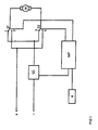
- Fig. 1 shows a block diagram of this device. It essentially consists of a DC motor M for two directions of rotation and a control circuit.
- This control circuit contains two controlled switches S1 and S2, preferably in the form of a relay, with switch positions 1 and 2 of switch S1 or 3 and 4 of switch S2.
- Motor M is connected to the DC supply voltage via these two switches S1 and S2. With switch positions 1/3, ie switch S1 in position 1 and switch S2 in position 3, or 2/4, ie switch S1 in position 2 and switch S2 in position 4, the motor is switched off.
- switch position 1/4 With switch position 1/4 the motor runs in a direction that is determined by the polarity of the supply voltage and with switch position 2/3 the motor runs in the opposite direction to switch position 1/4.
- the switches S1 and S2 are controlled by a control circuit contained in the computing unit MP in such a way that, depending on the requirements, they assume one of the switching positions described above.
- the supply circuit contains a current monitoring circuit, from which an actual signal, which indicates whether the motor is switched on or off, is sent to the computing unit MP. With this signal, a counter that indicates the current position is reset when the motor is switched off by a limit switch, i.e. when it has reached an end position, it is switched off.
- the arithmetic unit MP queries the state of the current monitoring circuit SÜ when a switch-off command is issued, ie when it controls the switches S1 and S2 into the switch position 1/3 or 2/4.
- the comparison circuit compares the state of the current monitoring circuit SÜ with the state of the control signal for switching the motor M on / off and outputs a signal corresponding to the comparison result. If this indicates that there is still current flow in the motor M, that is to say that the switch last actuated has not assumed its predetermined switching position, a control command contained in the computing unit MP issues a switching command to the other switch, so that the motor M is switched off .
- the switch position is 1/4, the motor M is running in a predetermined direction
- the current monitoring circuit SÜ shows the computing unit that the motor M is running. If a switching command is issued, which results in switch position 2/4, i.e. the motor is switched off, then the comparison circuit checks whether current still flows through the motor M when the switch-off signal is present. If this is the case, ie switch position 1/4 is still present because, for example, switch S1 is stuck, this is recognized and the control circuit switches switch S2 to position 3, so that switch position 1/3 is present and thus the motor M is switched off.
- a display unit is used so that the computing unit MP displays a corresponding error message when a switch S1 or S2 malfunctions.
Landscapes
- Control Of Position Or Direction (AREA)
- Variable-Direction Aerials And Aerial Arrays (AREA)
- Details Of Aerials (AREA)
Priority Applications (1)
| Application Number | Priority Date | Filing Date | Title |
|---|---|---|---|
| AT90115219T ATE102747T1 (de) | 1989-09-14 | 1990-08-08 | Einrichtung zum automatischen positionieren einer satellitenantenne. |
Applications Claiming Priority (2)
| Application Number | Priority Date | Filing Date | Title |
|---|---|---|---|
| DE3930723 | 1989-09-14 | ||
| DE3930723A DE3930723A1 (de) | 1989-09-14 | 1989-09-14 | Einrichtung zum automatischen positionieren einer satellitenantenne |
Publications (3)
| Publication Number | Publication Date |
|---|---|
| EP0417472A2 true EP0417472A2 (fr) | 1991-03-20 |
| EP0417472A3 EP0417472A3 (en) | 1991-07-24 |
| EP0417472B1 EP0417472B1 (fr) | 1994-03-09 |
Family
ID=6389426
Family Applications (1)
| Application Number | Title | Priority Date | Filing Date |
|---|---|---|---|
| EP90115219A Expired - Lifetime EP0417472B1 (fr) | 1989-09-14 | 1990-08-08 | Dispositif de positionnement automatique d'une antenne satellite |
Country Status (3)
| Country | Link |
|---|---|
| EP (1) | EP0417472B1 (fr) |
| AT (1) | ATE102747T1 (fr) |
| DE (2) | DE3930723A1 (fr) |
Cited By (3)
| Publication number | Priority date | Publication date | Assignee | Title |
|---|---|---|---|---|
| CN102323446A (zh) * | 2011-08-08 | 2012-01-18 | 珠海迈科电子科技有限公司 | 对控制极轴天线的马达的转动情况实现监测的方法和系统 |
| CN102723602A (zh) * | 2012-06-29 | 2012-10-10 | 深圳市九洲电器有限公司 | 一种自动寻星方法及寻星装置 |
| US20170373390A1 (en) * | 2016-06-28 | 2017-12-28 | Hong Fu Jin Precision Industry (Shenzhen) Co., Ltd | Satellite finding apparatus and satellite finding method |
Families Citing this family (1)
| Publication number | Priority date | Publication date | Assignee | Title |
|---|---|---|---|---|
| DE19953634B4 (de) * | 1999-11-09 | 2008-04-17 | Brose Fahrzeugteile Gmbh & Co. Kommanditgesellschaft, Coburg | Einrichtung und Verfahren zur Sicherung eines Lastelementes |
Family Cites Families (1)
| Publication number | Priority date | Publication date | Assignee | Title |
|---|---|---|---|---|
| DE3305770A1 (de) * | 1983-02-19 | 1984-08-23 | Robert Bosch Gmbh, 7000 Stuttgart | Schaltungsanordnung zum ein- und ausschalten eines elektromotorischen antriebes |
-
1989
- 1989-09-14 DE DE3930723A patent/DE3930723A1/de not_active Withdrawn
-
1990
- 1990-08-08 EP EP90115219A patent/EP0417472B1/fr not_active Expired - Lifetime
- 1990-08-08 DE DE90115219T patent/DE59004879D1/de not_active Expired - Lifetime
- 1990-08-08 AT AT90115219T patent/ATE102747T1/de not_active IP Right Cessation
Cited By (6)
| Publication number | Priority date | Publication date | Assignee | Title |
|---|---|---|---|---|
| CN102323446A (zh) * | 2011-08-08 | 2012-01-18 | 珠海迈科电子科技有限公司 | 对控制极轴天线的马达的转动情况实现监测的方法和系统 |
| CN102323446B (zh) * | 2011-08-08 | 2013-01-23 | 珠海迈科电子科技有限公司 | 对控制极轴天线的马达的转动情况实现监测的方法和系统 |
| CN102723602A (zh) * | 2012-06-29 | 2012-10-10 | 深圳市九洲电器有限公司 | 一种自动寻星方法及寻星装置 |
| US20170373390A1 (en) * | 2016-06-28 | 2017-12-28 | Hong Fu Jin Precision Industry (Shenzhen) Co., Ltd | Satellite finding apparatus and satellite finding method |
| CN107547876A (zh) * | 2016-06-28 | 2018-01-05 | 鸿富锦精密工业(深圳)有限公司 | 寻星装置及寻星方法 |
| US10389022B2 (en) * | 2016-06-28 | 2019-08-20 | Nanning Fugui Precision Industrial Co., Ltd. | Satellite finding apparatus and satellite finding method |
Also Published As
| Publication number | Publication date |
|---|---|
| EP0417472A3 (en) | 1991-07-24 |
| ATE102747T1 (de) | 1994-03-15 |
| DE59004879D1 (de) | 1994-04-14 |
| DE3930723A1 (de) | 1991-03-28 |
| EP0417472B1 (fr) | 1994-03-09 |
Similar Documents
| Publication | Publication Date | Title |
|---|---|---|
| DE19744465C1 (de) | Verfahren zur Überwachung eines Stufenschalters | |
| DE69417344T2 (de) | Fehlererkennungsvorrichtung für Relais | |
| EP1735888A1 (fr) | Moteur série et procédé de commande associé | |
| EP1363306B1 (fr) | Interrupteur de sécurité, circuit de sécurité et procédé de commande d'un interrupteur de sécurité | |
| EP0052759B1 (fr) | Dispositif dans un poste électronique d'aguillage pour l'alimentation et le télécontrôle de la commande d'aiguilles | |
| EP1182762B1 (fr) | Outil électrique et procédé pour son utilisation | |
| DE2809596C2 (fr) | ||
| DE69425056T2 (de) | Brandschutzklappe mit ansteuersystem | |
| DE3401761C2 (de) | Regeleinrichtung | |
| EP0417472B1 (fr) | Dispositif de positionnement automatique d'une antenne satellite | |
| DE4403375A1 (de) | Einrichtung und Verfahren zum Steuern eines induktiven Verbrauchers | |
| DE3902037C1 (fr) | ||
| DE19622639A1 (de) | Schnittstellenvorrichtung für einen Scheibenrepeater | |
| DE4416008A1 (de) | Mit einem Regelsystem ausgerüstetes Fahrzeug | |
| DE2917529C2 (de) | Verfahren und Prüfgerät zur Gewährleistung der Betriebssicherheit von mit elektrischen Stellantrieben versehenen Armaturen | |
| EP1958223B1 (fr) | Commande de changement de rapport de transmission dotee d'un dispositif de surveillance du changement de rapport | |
| DE19534715A1 (de) | Sicherheitsschaltung für einen relaisgesteuerten Elektromotor | |
| DE4322472B4 (de) | Schaltungsanordnung zur Überwachung eines Stellungsgebers | |
| DE3246385A1 (de) | Schaltung zur ueberwachung der schaltfunktion von halbleiterschaltern | |
| EP1081431A2 (fr) | Appareil de commande pour installations thermiques | |
| DE19843343C2 (de) | Überwachung von Motorrelais bei Garagentorantrieben | |
| EP0404143B1 (fr) | Circuit pour surveiller des charges à courant alternatif dans des installations de chemin de fer | |
| DE2038031C3 (de) | Schaltungsanordnung zum Umstellen und Überwachen von Weichen mit Drehstromantrieben | |
| DE68918208T2 (de) | Zwei Fehler tolerierendes Betätigungsgerät. | |
| DE3042019A1 (de) | Schaltanordnung fuer eine pendelwischanlage |
Legal Events
| Date | Code | Title | Description |
|---|---|---|---|
| PUAI | Public reference made under article 153(3) epc to a published international application that has entered the european phase |
Free format text: ORIGINAL CODE: 0009012 |
|
| AK | Designated contracting states |
Kind code of ref document: A2 Designated state(s): AT DE FR GB |
|
| PUAL | Search report despatched |
Free format text: ORIGINAL CODE: 0009013 |
|
| AK | Designated contracting states |
Kind code of ref document: A3 Designated state(s): AT DE FR GB |
|
| 17P | Request for examination filed |
Effective date: 19910822 |
|
| 17Q | First examination report despatched |
Effective date: 19930817 |
|
| GRAA | (expected) grant |
Free format text: ORIGINAL CODE: 0009210 |
|
| AK | Designated contracting states |
Kind code of ref document: B1 Designated state(s): AT DE FR GB |
|
| REF | Corresponds to: |
Ref document number: 102747 Country of ref document: AT Date of ref document: 19940315 Kind code of ref document: T |
|
| GBT | Gb: translation of ep patent filed (gb section 77(6)(a)/1977) |
Effective date: 19940314 |
|
| REF | Corresponds to: |
Ref document number: 59004879 Country of ref document: DE Date of ref document: 19940414 |
|
| ET | Fr: translation filed | ||
| REG | Reference to a national code |
Ref country code: GB Ref legal event code: 746 Effective date: 19940926 |
|
| REG | Reference to a national code |
Ref country code: FR Ref legal event code: DL |
|
| PLBE | No opposition filed within time limit |
Free format text: ORIGINAL CODE: 0009261 |
|
| STAA | Information on the status of an ep patent application or granted ep patent |
Free format text: STATUS: NO OPPOSITION FILED WITHIN TIME LIMIT |
|
| 26N | No opposition filed | ||
| REG | Reference to a national code |
Ref country code: FR Ref legal event code: CD |
|
| REG | Reference to a national code |
Ref country code: FR Ref legal event code: TP |
|
| PGFP | Annual fee paid to national office [announced via postgrant information from national office to epo] |
Ref country code: AT Payment date: 19990831 Year of fee payment: 10 |
|
| PG25 | Lapsed in a contracting state [announced via postgrant information from national office to epo] |
Ref country code: AT Free format text: LAPSE BECAUSE OF NON-PAYMENT OF DUE FEES Effective date: 20000808 |
|
| REG | Reference to a national code |
Ref country code: GB Ref legal event code: IF02 |
|
| REG | Reference to a national code |
Ref country code: GB Ref legal event code: 732E |
|
| REG | Reference to a national code |
Ref country code: FR Ref legal event code: TP |
|
| PGFP | Annual fee paid to national office [announced via postgrant information from national office to epo] |
Ref country code: GB Payment date: 20090826 Year of fee payment: 20 Ref country code: DE Payment date: 20090827 Year of fee payment: 20 |
|
| REG | Reference to a national code |
Ref country code: GB Ref legal event code: PE20 Expiry date: 20100807 |
|
| PG25 | Lapsed in a contracting state [announced via postgrant information from national office to epo] |
Ref country code: GB Free format text: LAPSE BECAUSE OF EXPIRATION OF PROTECTION Effective date: 20100807 |
|
| PGFP | Annual fee paid to national office [announced via postgrant information from national office to epo] |
Ref country code: FR Payment date: 20090909 Year of fee payment: 20 |
|
| PG25 | Lapsed in a contracting state [announced via postgrant information from national office to epo] |
Ref country code: DE Free format text: LAPSE BECAUSE OF EXPIRATION OF PROTECTION Effective date: 20100808 |