EP0417658A1 - Vorrichtung zum automatischen Fördern und Entnehmen eines Werkstückträgers einer Nähmaschine - Google Patents
Vorrichtung zum automatischen Fördern und Entnehmen eines Werkstückträgers einer Nähmaschine Download PDFInfo
- Publication number
- EP0417658A1 EP0417658A1 EP90117258A EP90117258A EP0417658A1 EP 0417658 A1 EP0417658 A1 EP 0417658A1 EP 90117258 A EP90117258 A EP 90117258A EP 90117258 A EP90117258 A EP 90117258A EP 0417658 A1 EP0417658 A1 EP 0417658A1
- Authority
- EP
- European Patent Office
- Prior art keywords
- workholder
- displacement means
- sewing
- automatic feeding
- withdrawal
- Prior art date
- Legal status (The legal status is an assumption and is not a legal conclusion. Google has not performed a legal analysis and makes no representation as to the accuracy of the status listed.)
- Withdrawn
Links
- 238000009958 sewing Methods 0.000 title claims abstract description 49
- 238000006073 displacement reaction Methods 0.000 claims abstract description 65
- 239000000463 material Substances 0.000 claims abstract description 18
- 230000008878 coupling Effects 0.000 claims description 18
- 238000010168 coupling process Methods 0.000 claims description 18
- 238000005859 coupling reaction Methods 0.000 claims description 18
- 238000004804 winding Methods 0.000 claims description 4
- 239000012530 fluid Substances 0.000 claims description 2
- 238000010276 construction Methods 0.000 description 2
- 238000000034 method Methods 0.000 description 1
- 230000003287 optical effect Effects 0.000 description 1
- 230000000284 resting effect Effects 0.000 description 1
- 239000007779 soft material Substances 0.000 description 1
- 230000001360 synchronised effect Effects 0.000 description 1
Images


Classifications
-
- D—TEXTILES; PAPER
- D05—SEWING; EMBROIDERING; TUFTING
- D05B—SEWING
- D05B33/00—Devices incorporated in sewing machines for supplying or removing the work
Definitions
- the present invention relates to an apparatus for the automatic feeding to and withdrawal from an automated sewing machine of a workholder containing a material to be sewn.
- the apparatus comprises: - a working plane on which two workholders may independently and simultaneously move in the x direction towards or away from a sewing head, or in the y direction; - at least two displacement means movable in the x direction; - at least one displacement means movable in the y direction; and - control means for controlling the movement of the displacement means.
- each displacement means comprises a moving body and coupling means for the coupling of the moving body with the workholder.
- the coupling means may comprise, e.g., a clamp or two or more pins.
- the moving body may be displaced in the x or y direction by any means known to a person skilled in the art. According to one embodiment of the invention, the moving body is slidably movable along a rail or the like slide base.
- the displacement of the moving body can be done utilizing different techniques well known to the skilled engineer.
- the moving body may be actuated by an electric motor, or by compressed air.
- a tension cable and winding means can be provided, to move the moving body forward and backward by the tension of the cable winding around the winding means.
- one x displacement means is connected to the second displacement means via a cable, and only one motor or the like is provided, which actuates both moving bodies.
- Controlling may be easily achieved by control means known in the art, such as control means which comprise a microprocessor or the like, such as a personal computer or a minicomputer.
- a workholder that can be used in conjunction with the apparatus of the invention also forms part of this invention.
- a workholder comprises a frame within which a piece of material to be sewn is fastened, a clampable end for the x-y clamping device, positioned on one side of the workholder frame, and at least two receiving means for the coupling means of the displacement means, positioned on two other adjacent sides.
- the receiving means comprise two or more holes.
- the coupling means will comprise a corresponding number of pins. These pins will move upwards and downwards, as dictated by the controlling means, and engage or disengage the workholder, accordingly.
- the workholder may be engaged by clamps provided on the moving bodies, if so desired, which clamps will be opened and closed by the same controlling means hereinbefore discussed with reference to the movement of the pins.
- An apparatus for the automated sewing of a piece of material is also encompassed by the invention.
- This apparatus comprises: - a sewing head; - automatic feeding and withdrawal apparatus of the invention; - an x-y system, to move the workholder to the sewing position and during sewing operations; and - at least one microprocessor to control the operation of the sewing head, of the automatic feeding and withdrawal apparatus and of the x-y system.
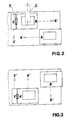
- an automatic sewing apparatus comprising an apparatus for the automatic feeding according to the invention, comprises a working plane, 1, a sewing head, 2, x-y apparatus 3, clamping means of the x-y apparatus, 4, and apparatus for the automatic feeding, 5.
- the automatic feeding apparatus 5, which is shown in a slightly detached position in Fig. 1, is positioned close to the working plane 1, so that its own working plane 6 is on the same level as working plane 1, and in fact constitutes a continuation of the same plane.
- a workholder B is positioned in the sewing position, below the sewing head 2 which is actually working
- the workholder B is attached to the x-y system, indicated by X in the figure, through the clamping means 4.
- a second workholder, indicated by A is waiting and is charged with the material to be sewn.
- clamping means 4 will open up and the workholder B will move in the direction of the arrow B′, by means of the displacement means (not shown in the figure).
- the workholder A will move towards the sewing apparatus, in the direction of the arrow A′, and the x-y system will move towards it, in the direction of the arrow X′.
- the apparatus 5 comprises a slot 7 provided in its middle.
- This slot houses displacement means 8, which can move in the x direction along the slot, as shown by the dotted lines.
- These displacement means are used to displace the workholder, the sewing of which has been completed, away from the sewing head.
- Additional similar displacement means 8′ are provided at the lower side of the working plane. These displacement means are used to move the newly charged workholder towards the x-y system.
- displacement means 8 ⁇ movable in the y direction, are provided, to move the already-sewn workholder from the upper position to the lower position, in which it can be discharged by the operator, and then recharged anew.
- the displacement means 8-8 ⁇ comprise coupling means which engage the workholder, so that it moves along with the displacement means, when they move. These coupling means, therefore, may be in the "engaged” position, in which they are coupled with the workholder, or in the "disengaged” position, in which the displacement means run freely, without causing a movement of the workholder.
- displacement means 8 will be in the 8b position, and disengaged.
- Displacement means 8′ will be in the 8′b position, and either engaged or disengaged, but they must engage workholder A, before the next step, if disengaged.
- Displacement means 8 ⁇ can be either in the 8 ⁇ a position, or in the 8 ⁇ b position and disengaged, but they must move to the 8 ⁇ a position before the next step.
- displacement means 8′ must be engaged in the 8′b position, before movement of workholder A begins, and displacement means 8 must engage workholder B in the 8b position, before movement thereof begins.
- displacement means 8′ must disengage workholder A′, and either return to the 8′b position, or be ready to return thereto.
- Displacement means 8 must be in the 8a position and disengaged, and 8 ⁇ in the 8 ⁇ a position, and engaged.
- displacement means 8 must be disengaged, and may be either in the 8b or 8a position
- displacement means 8′ must be in the 8′b position, either engaged or disengaged
- 8 ⁇ must be in the 8 ⁇ a position, or in the 8 ⁇ b position and ready to move to the 8 ⁇ a position.
- displacement means 8 While providing the displacement means 8 in the slot 7 is convenient, because they utilize the same receiving means provided in the workholder for the coupling means as are utilized by displacement means 8′, it will be clear to a person skilled in the art that the displacement means 8 may be positioned at the upper side of the working plane, symmetrically with displacement means 8′, and the slot 7 can be dispensed with. The only addition in this case will be to provide receiving means also in the upper portion of the workholder, for the coupling means of displacement means 8.
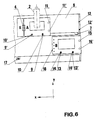
- FIG. 6 an apparatus according to one preferred embodiment of the invention is shown.
- This apparatus utilizes pins as the coupling means of the displacement means. Therefore, the receiving means for the coupling means are holes drilled in the frame of the workholder.
- the pins which constitute the displacement means 8 of Fig. 5 are indicated by 9 and 9′ in the figure, and engage holes 10 and 10′ respectively. Additional holes 11 and 11′ are provided in workholder A, as shown in the figure. These will be engaged by pins 12 and 12′ which constitute the displacement means 8 ⁇ of Fig. 5.
- the displacement means 8′ of Fig. 5 are, in the embodiment of Fig. 6, the two pins 13 and 13′ which engage holes 14 and 14′ of workholder B.
- Additional holes 15 and 15′ will be engaged by pins 12 and 12′, to provide for the displacement of the workholder in the y direction.
- a clampable end 16 is also shown on workholder B, which can be engaged by the clamping means 4 of the x-y system X.
- safety means 17 are provided, which stop the operation of the system when the hands of the operator are extended towards the workplane, so that when the operator discharges and charges workholder B, the system cannot be operated by mistake.
- the safety means 17 can be any means known in the art, such as light detecting or body-heat detecting apparatus.
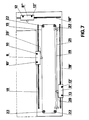
- each displacement means is positioned on a rail.
- displacement means 8 of Fig. 5 is positioned on a rail 18, displacement means 8′ on a rail 18′, and 8 ⁇ on a rail 18 ⁇ .
- the pins are also shown in Fig. 7, and indicated by the same numerals as in Fig. 6.
- a cable 19 attached to an attachment 20 of the displacement means 8 causes the body of the displacement means 8 to move along the rail 18, when the cable 19 is caused to move by the action of, e.g., a piston-and-cable arrangement 21.
- the same apparatus can be provided for all other displacement means. These, of course, can also be actuated by other power means, such as an electric motor.
- the piston-and-cable assembly 21 is utilized to move both displacement means 8 and 8′ together, by the action of common cable 19 which is kept in tension by and slides on appropriate rollers 22.
- This although economically advantageous, clearly has the disadvantage that both displacement means must move synchronically. If it is devised to permit an independent motion of these displacement means, separate power or actuating means must be provided. Similar apparatus is provided for displacement means 8 ⁇ (not shown in the figure).
- Displacement means 8 are located, with respect to Fig. 6, in the central slot 7. The working plane will therefore extend beyond the rail 18, as shown in broken lines in Fig. 7.
- the pins 10, 10′ of displacement means 8, and the corresponding pins of the displacement means 8′ and 8 ⁇ , can be moved upwards and downwards by any suitable means, such as electrical and/or mechanical means which can push them upwards, or the displacement means can be coupled to a compressed air outlet at the engagement and disengagement position, so that compressed air can be used to push the pins upwards or to release them at will, at predetermined engagement/disengagement positions.
- Fig. 8 is a schematic detailed view of the engagement and disengagement means, according to one embodiment of the invention.
- the workholder 23, resting on the working plane 6, is disengaged.
- Two pins 24 are positioned outside the working plane and below its level.
- the pins 24 are connected through a bar 25 to a piston (not shown), located within the housing 26 which is positioned, e.g., on the displacement means 8′ of Fig. 7 (not shown).
- the housing 26 is connected to a supply of compressed air or other fluid, through hose 27. (Alternatively, housing 26 may contain electromagnets and 27 may be an electric wire.)
- the pin may have a tapered top, to permit engagement if a minor mismatch in the relative positioning of the pins and holes occurs, and these are thus misaligned.
- the pin head furthermore, may be made of soft material, such as rubber. The pin can, of course, be withdrawn to disengage the workholder and to return to the position of Fig. 8(a), by means known to the skilled technician and which depend on the particular actuation system employed.
- position detectors for the various coupling and displacement means, to provide positive and safe control of the position of the various moving parts.
- These position detectors may be, e.g., microswitches, optical detectors, etc., and are of course well within the scope of a person skilled in the art.
Landscapes
- Engineering & Computer Science (AREA)
- Textile Engineering (AREA)
- Sewing Machines And Sewing (AREA)
Applications Claiming Priority (2)
| Application Number | Priority Date | Filing Date | Title |
|---|---|---|---|
| IL91595 | 1989-09-11 | ||
| IL91595A IL91595A0 (de) | 1989-09-11 | 1989-09-11 |
Publications (1)
| Publication Number | Publication Date |
|---|---|
| EP0417658A1 true EP0417658A1 (de) | 1991-03-20 |
Family
ID=11060385
Family Applications (1)
| Application Number | Title | Priority Date | Filing Date |
|---|---|---|---|
| EP90117258A Withdrawn EP0417658A1 (de) | 1989-09-11 | 1990-09-07 | Vorrichtung zum automatischen Fördern und Entnehmen eines Werkstückträgers einer Nähmaschine |
Country Status (2)
| Country | Link |
|---|---|
| EP (1) | EP0417658A1 (de) |
| IL (1) | IL91595A0 (de) |
Cited By (3)
| Publication number | Priority date | Publication date | Assignee | Title |
|---|---|---|---|---|
| WO1994004735A1 (en) * | 1992-08-12 | 1994-03-03 | De Montfort University | Knitting and handling of articles |
| EP0568504A3 (de) * | 1992-04-28 | 1995-02-15 | Vibemac Srl | Spannvorrichtung oder Schablonenführung und Vorrichtung zur Vorpositionierung und Verschiebung eines Gewebestücks sowie zum Kuppeln derselben an eine programmierbare Nähmaschine. |
| US20230392311A1 (en) * | 2020-10-21 | 2023-12-07 | Borsoi S.R.L. | Machine for sewing bag envelopes |
Citations (2)
| Publication number | Priority date | Publication date | Assignee | Title |
|---|---|---|---|---|
| US3669046A (en) * | 1970-07-17 | 1972-06-13 | Textiles Inc | Overedging apparatus |
| US3769924A (en) * | 1972-03-10 | 1973-11-06 | W Rogers | Profile sewing apparatus |
-
1989
- 1989-09-11 IL IL91595A patent/IL91595A0/xx unknown
-
1990
- 1990-09-07 EP EP90117258A patent/EP0417658A1/de not_active Withdrawn
Patent Citations (2)
| Publication number | Priority date | Publication date | Assignee | Title |
|---|---|---|---|---|
| US3669046A (en) * | 1970-07-17 | 1972-06-13 | Textiles Inc | Overedging apparatus |
| US3769924A (en) * | 1972-03-10 | 1973-11-06 | W Rogers | Profile sewing apparatus |
Cited By (6)
| Publication number | Priority date | Publication date | Assignee | Title |
|---|---|---|---|---|
| EP0568504A3 (de) * | 1992-04-28 | 1995-02-15 | Vibemac Srl | Spannvorrichtung oder Schablonenführung und Vorrichtung zur Vorpositionierung und Verschiebung eines Gewebestücks sowie zum Kuppeln derselben an eine programmierbare Nähmaschine. |
| WO1994004735A1 (en) * | 1992-08-12 | 1994-03-03 | De Montfort University | Knitting and handling of articles |
| GB2283986A (en) * | 1992-08-12 | 1995-05-24 | Univ Montfort | Knitting and handling of articles |
| GB2283986B (en) * | 1992-08-12 | 1996-09-11 | Univ Montfort | Knitting and handling of articles |
| US20230392311A1 (en) * | 2020-10-21 | 2023-12-07 | Borsoi S.R.L. | Machine for sewing bag envelopes |
| US12247335B2 (en) * | 2020-10-21 | 2025-03-11 | Borsoi S.R.L. | Machine for sewing bag envelopes |
Also Published As
| Publication number | Publication date |
|---|---|
| IL91595A0 (de) | 1990-04-29 |
Similar Documents
| Publication | Publication Date | Title |
|---|---|---|
| US5033785A (en) | Clamp mechanism | |
| EP0117273B1 (de) | Vorrichtung zum automatischen Befestigen von Steckern an Kabelenden | |
| EP0983810A2 (de) | Automatische Werkzeugwechselvorrichtung | |
| JPS6213135B2 (de) | ||
| EP0512649A1 (de) | Nietmaschine | |
| CN109304412B (zh) | 裸钢丝绳两端铆接自动加工设备 | |
| CN206123130U (zh) | 一种全自动安全扣组装机 | |
| CN116741529B (zh) | 一种多轴绕线机及多轴绕线方法 | |
| CN106956799B (zh) | 一种用于吊牌的自动化穿绳机构 | |
| CA1038698A (en) | Loader-unloader for automatic sewing apparatus | |
| KR20230153938A (ko) | 터미널 압착 어플리케이터 시스템 | |
| EP0417658A1 (de) | Vorrichtung zum automatischen Fördern und Entnehmen eines Werkstückträgers einer Nähmaschine | |
| CN114068170B (zh) | 一种平板电感线圈全自动生产设备 | |
| JPH04231127A (ja) | 特定のワイヤのかせ形素材のための曲げ機械 | |
| US4299179A (en) | Method and installation for supplying a sewing machine | |
| CN215431380U (zh) | 一种托盘手柄自动铆接机 | |
| CN218447050U (zh) | 一种工业机器人自动上下料实训装置 | |
| JP2892928B2 (ja) | 部品供給方法および装置 | |
| GB1023594A (en) | Improvements in or relating to automatic devices,applied to sewing machines,for feeding fabric | |
| CN110693120B (zh) | 一种钉扣机自动送扣装置 | |
| CN112958742A (zh) | 一种托盘手柄自动铆接机及其工作方法 | |
| CN223194205U (zh) | 一种柔性连接线的铆接装置 | |
| CN213890053U (zh) | 一种防损坏的机器人机械夹爪结构 | |
| GB2145022A (en) | A riveter | |
| CN209691735U (zh) | 一种led灯焊线设备的料盒下料装置 |
Legal Events
| Date | Code | Title | Description |
|---|---|---|---|
| PUAI | Public reference made under article 153(3) epc to a published international application that has entered the european phase |
Free format text: ORIGINAL CODE: 0009012 |
|
| AK | Designated contracting states |
Kind code of ref document: A1 Designated state(s): DE FR GB |
|
| STAA | Information on the status of an ep patent application or granted ep patent |
Free format text: STATUS: THE APPLICATION HAS BEEN WITHDRAWN |
|
| 18W | Application withdrawn |
Withdrawal date: 19910904 |
|
| R18W | Application withdrawn (corrected) |
Effective date: 19910904 |