EP0417744A2 - Palier isolé À©lectriquement - Google Patents
Palier isolé À©lectriquement Download PDFInfo
- Publication number
- EP0417744A2 EP0417744A2 EP90117518A EP90117518A EP0417744A2 EP 0417744 A2 EP0417744 A2 EP 0417744A2 EP 90117518 A EP90117518 A EP 90117518A EP 90117518 A EP90117518 A EP 90117518A EP 0417744 A2 EP0417744 A2 EP 0417744A2
- Authority
- EP
- European Patent Office
- Prior art keywords
- outer ring
- bearing
- insulating
- thin film
- metallic plate
- Prior art date
- Legal status (The legal status is an assumption and is not a legal conclusion. Google has not performed a legal analysis and makes no representation as to the accuracy of the status listed.)
- Granted
Links
Images


Classifications
-
- F—MECHANICAL ENGINEERING; LIGHTING; HEATING; WEAPONS; BLASTING
- F16—ENGINEERING ELEMENTS AND UNITS; GENERAL MEASURES FOR PRODUCING AND MAINTAINING EFFECTIVE FUNCTIONING OF MACHINES OR INSTALLATIONS; THERMAL INSULATION IN GENERAL
- F16C—SHAFTS; FLEXIBLE SHAFTS; ELEMENTS OR CRANKSHAFT MECHANISMS; ROTARY BODIES OTHER THAN GEARING ELEMENTS; BEARINGS
- F16C35/00—Rigid support of bearing units; Housings, e.g. caps, covers
- F16C35/04—Rigid support of bearing units; Housings, e.g. caps, covers in the case of ball or roller bearings
- F16C35/06—Mounting or dismounting of ball or roller bearings; Fixing them onto shaft or in housing
- F16C35/07—Fixing them on the shaft or housing with interposition of an element
- F16C35/077—Fixing them on the shaft or housing with interposition of an element between housing and outer race ring
-
- F—MECHANICAL ENGINEERING; LIGHTING; HEATING; WEAPONS; BLASTING
- F16—ENGINEERING ELEMENTS AND UNITS; GENERAL MEASURES FOR PRODUCING AND MAINTAINING EFFECTIVE FUNCTIONING OF MACHINES OR INSTALLATIONS; THERMAL INSULATION IN GENERAL
- F16C—SHAFTS; FLEXIBLE SHAFTS; ELEMENTS OR CRANKSHAFT MECHANISMS; ROTARY BODIES OTHER THAN GEARING ELEMENTS; BEARINGS
- F16C19/00—Bearings with rolling contact, for exclusively rotary movement
- F16C19/52—Bearings with rolling contact, for exclusively rotary movement with devices affected by abnormal or undesired conditions
-
- F—MECHANICAL ENGINEERING; LIGHTING; HEATING; WEAPONS; BLASTING
- F16—ENGINEERING ELEMENTS AND UNITS; GENERAL MEASURES FOR PRODUCING AND MAINTAINING EFFECTIVE FUNCTIONING OF MACHINES OR INSTALLATIONS; THERMAL INSULATION IN GENERAL
- F16C—SHAFTS; FLEXIBLE SHAFTS; ELEMENTS OR CRANKSHAFT MECHANISMS; ROTARY BODIES OTHER THAN GEARING ELEMENTS; BEARINGS
- F16C27/00—Elastic or yielding bearings or bearing supports, for exclusively rotary movement
- F16C27/06—Elastic or yielding bearings or bearing supports, for exclusively rotary movement by means of parts of rubber or like materials
- F16C27/066—Ball or roller bearings
-
- F—MECHANICAL ENGINEERING; LIGHTING; HEATING; WEAPONS; BLASTING
- F16—ENGINEERING ELEMENTS AND UNITS; GENERAL MEASURES FOR PRODUCING AND MAINTAINING EFFECTIVE FUNCTIONING OF MACHINES OR INSTALLATIONS; THERMAL INSULATION IN GENERAL
- F16C—SHAFTS; FLEXIBLE SHAFTS; ELEMENTS OR CRANKSHAFT MECHANISMS; ROTARY BODIES OTHER THAN GEARING ELEMENTS; BEARINGS
- F16C33/00—Parts of bearings; Special methods for making bearings or parts thereof
- F16C33/30—Parts of ball or roller bearings
- F16C33/58—Raceways; Race rings
- F16C33/583—Details of specific parts of races
- F16C33/586—Details of specific parts of races outside the space between the races, e.g. end faces or bore of inner ring
-
- F—MECHANICAL ENGINEERING; LIGHTING; HEATING; WEAPONS; BLASTING
- F16—ENGINEERING ELEMENTS AND UNITS; GENERAL MEASURES FOR PRODUCING AND MAINTAINING EFFECTIVE FUNCTIONING OF MACHINES OR INSTALLATIONS; THERMAL INSULATION IN GENERAL
- F16C—SHAFTS; FLEXIBLE SHAFTS; ELEMENTS OR CRANKSHAFT MECHANISMS; ROTARY BODIES OTHER THAN GEARING ELEMENTS; BEARINGS
- F16C41/00—Other accessories, e.g. devices integrated in the bearing not relating to the bearing function as such
- F16C41/002—Conductive elements, e.g. to prevent static electricity
-
- F—MECHANICAL ENGINEERING; LIGHTING; HEATING; WEAPONS; BLASTING
- F16—ENGINEERING ELEMENTS AND UNITS; GENERAL MEASURES FOR PRODUCING AND MAINTAINING EFFECTIVE FUNCTIONING OF MACHINES OR INSTALLATIONS; THERMAL INSULATION IN GENERAL
- F16C—SHAFTS; FLEXIBLE SHAFTS; ELEMENTS OR CRANKSHAFT MECHANISMS; ROTARY BODIES OTHER THAN GEARING ELEMENTS; BEARINGS
- F16C2202/00—Solid materials defined by their properties
- F16C2202/30—Electric properties; Magnetic properties
Definitions
- This invention relates to an electrical insulating bearing.
- a conventional bearing having a rolling element interposed between an outer ring and an inner ring has been known in the art.
- shaft voltage is usually generated between both ends of a rotary shaft, between the rotary shaft and each bearing, or in engaging sections of the rotary shaft with each bearing.
- This shaft voltage is generated due to various reasons such as, magnetic unbalance, static storage, direct application of an external power source to the rotary shaft, and an induced electricity generated in the shaft with the use of a rectifier power source. Excessive generation of this shaft voltage causes shaft current to flow through each bearing portion, resulting in wear in the bearings. damage to the rotary shaft, and blackening of lubricating oil, or in some cases, damage to or scorch of bearing.
- Japanese utility Model Registration Application Laying-open Gazette No.60-161721 discloses a technique of insulating a bearing with a ceramic layer.
- the bearing is treated with a ceramic surface finishing process to form a ceramic layer thereon.
- Synthetic plastic resin having elasticity and viscosity is then poured into porous portions of the ceramics in order to reinforce the ceramic layers.
- Japanese Patent Application Laying-open Gazette No.59-103023 discloses a technique of forming an insulating coating of inorganic compounds with a thermal spraying method.
- Japanese Patent Application No.53-81459 discloses a technique of forming an insulating coating with a baking or a coating method.
- Japanese Utility Model Registration Application Laying-open Gazette No. 59-173467 discloses an insulating technique using a ceramic coating formed by a thermal spraying method.
- Japanese utility Model Registration Application Laying-open Gazette No.54-105408 discloses a technique of forming an insulating polymer member to cover an outer peripheral surface and a side surface of an outer ring.
- Japanese Utility Model Registration Application Laying-open Gazette No.58-33820 discloses a technique of interposing an electrical insulating member between an outer ring and a saddle. In this application, this electrical insulating member is formed in such a manner that a coating member of polyer elastic materal is sandwiched between thin metallic plates.
- Bearings used in main electric motors for rolling stooks are generally installed onto end covers (mounting portions of bearings) of main electric motors. Accordingly, an installation work of a bearing to this cover is necessary. In this sense, higher dimensional accuracy is required for bearings. However, this higher dimensional accuracy cannot be obtained easily when it comes to bearings having insulating members. As a result, overall dimensional accuracy in installation lowers when installing these bearings with lower dimensional accuracy.
- a ceramic-treated bearing has succeeded in improving its dimensional accuracy, but not in overcoming brittleness of ceramic itself.
- insulating capacity of the bearing from the cover of the main electric motors can be evaluated only after installation.
- a technique using the polymer insulating materials alone is disadvantageous since it is impossible to raise the dimensional accuracy of the polymer member itself.
- an insulating material is made into a form of a thin layer in order to lessen the amount of distortion when load acts upon the bearing. But this tends to cause damages to the polymer member or ceramic materials upon installation or removal of the bearing.
- an insulating thin film made of polymer elastic material, and a thin metallic plate are used to provide an outer ring itself of the bearing with an electrical insulating property. Accordingly, in this invention, an electrical insulating property of a bearing itself can be evaluated even before installation, and at the same time, requirement for dimensional accuracy and also for easy and accurate installation can be satisfied.
- an electrical insulating bearing having a rolling element interposed between an outer ring and an inner ring, wherein a metallic outer ring body having a path of rotation of the rolling element, an insulating thin film, being made of polymer elastic material having an electrical insulating property, and coating a portion where the outer ring body is mounted to a housing, and a thin metallic plate provided on an outer surface of the insulating thin film, are integrated into a solid one-piece body to form the outer ring.
- the outer ring Since the outer ring is formed by integrating the outer ring body, the insulating thin film and the thin metallic plate, the outer ring itself in the above bearing has insulating property for electrically insulating the bearing from a housing portion. Accordingly, an electrical resistance between the outer ring body and the thin metallic plate can be measured before installation to the housing to evaluate insulating property of the bearing.
- the insulating thin film is made of polymer elastic materials so as to have elasticity or toughness. This means that the insulating thin film has damping effect against oscillation as well as resistance against fracture caused by heavy load during operation.
- the thin metallic plate protects the insulating thin film from scratch or damage upon installation of the bearing onto the housing as well as from breakage due to heavy load during operation.
- the outer ring body, the insulating thin film and the thin metallc plate are integrated to make up the outer ring of the bearing in the present invention.
- the outer ring of the bearing is provided with electrical insulating property as well as elasticity or toughness without impairing the dimensional accuracy thereof. Electrical insulating property can be evaluated for each bearing separately before installation. Further, electrical insulation can be accomplished between the bearing and the housing only by installing the bearing onto the housing. Since there is no need to provide any additional electrical insulating member between the bearing and the housing, installation accuracy of the bearing and the dimensional accuracy of the bearing portion can be improved. Also, the insulating thin film can be protected by the thin metallic plate.
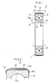
- Fig.1 shows an insulating bearing 1 installed onto an end cover of a main electric motor.
- This bearing 1 is made up by interposing a plurality of rolling elements (a ball or a roller) 6 between an outer ring 3 and an inner ring 5.
- the outer ring 3 is fixed onto the cover of the main electric motor (hereinafter called a housing 2).
- An armature shaft 4 is inserted in the inner ring 5.
- the outer ring 3 is made up by integrating the following three elements into a solid one-piece body: an outer ring body 11; an insulating thin film 12 which covers an outer periphery of the outer ring body 11; and a thin metallic plate 13 which is provided on an outer surface of the insulating thin film 12.
- the outer ring body 11 is made of metal, and accordingly has conductivity.
- the outer ring body 11 has a path 11a of the rolling element 6 in an inner periphery thereof.
- the insulating thin film 12 is made of polymer elastic materials. This insulating thin film 12 is provided on a portion extending from an outer peripheral surface 11b to a side surface 11c of the outer ring body 11 so as to electrically insulate the outer ring body 11 from the housing 2.
- the thin metallic plate 13 is adhered to the insulating thin film 12 on a portion corresponding to the outer peripheral surface 11b of the outer ring body 11. However, the thin metallic plate 13 is provided on the insulating thin film 12 while leaving an exposed portion in the periphery of the insulating thin film 12 so as not to make direct contact with the outer ring body 11.
- Desirable thickness and property of the insulating thin film 12, and desirable thickness of the thin metallic plate 13 when an outer diameter of the outer ring 3 is approximately 170 mm are as follows. insulating thin film thickness from 0.1 to 2.0 mm shore hardness from 80A to 60D electrical resistance not less than 100M ⁇ thickness of thin metallic plate 1.0 mm
- Thickness of the insulating thin film 12 and the thin metallic plate 13 in the above table is shown by thickness in the superposed portions thereof.
- the inner ring 5 has a path 5a of the rolling element 6 in the outer periphery thereof.
- Each rolling element 6 is supported by a cage 7.
- These inner ring 5, rolling element 6, and cage 7 are made of metal, and therefore, have conductivity.
- FIG.3 A metal mold shown in Fig.3 is utilized in this method of manufacturing the outer ring 3.
- reference numeral 15 designates a lower die wherein the outer ring body 11 is inserted.
- Reference numeral 16 designates an upper die which covers the outer ring body 11
- reference numeral 17 designates an outer die for positioning a thin metallic plate member 13A onto the outer ring body 11 as well as for molding a cavity 19 to form the insulating thin film 12 in association with the lower die
- reference numeral 18 designates an outer frame for fixing the outer die 17.
- the outer die 17 is split in the circumferential direction.
- the method of manufacturing the outer ring 3 comprises the following steps:
- composition of the polymer elastic material is as follows.
- PTMEG polytetramethyleneglycol manufactured by Mitsui-toatsu Co., L-100
- CURAMINE MT (3,3-dichloro-4,4-diaminodiphenylmethane) 19 weight part (120°C)
- the insulating thin film 12 of the outer ring 3 is made of polyurethane.
- the outer ring 3 possesses capacity of insulating the bearing 1 from the housing 2.
- insulation property of the outer ring 3 can be evaluated by measuring electrical resistance between the outer ring body 11 and the thin metallic plate 13 at the time when the production of the outer ring 3 is completed.
- the superposed portion of the insulating thin film 12 and the thin metallic plate 13 were 0.5 mm, 1.0 mm respectively in thickness, and electrical resistance was not less than 100 M ⁇ .
- the bearing 1 is installed onto the housing 2 and the armature 4. While the bearing 1 is installed on the housing 2 and the armature 4, no discharge occurs from the housing 2 to the armature 4 since not less than 100 M ⁇ electrical resistance exists in the insulating thin film 12 of the bearing 1. Accordingly, the bearing 1 will never wear excessively.
- the thin metallic plate 13 is provided inside the periphery portion of the insulating thin film 12 so as not to make contact with the outer ring body 11. This means that the thin metallic plate 13 does not adversely affect electrical insulating property of the bearing 1. In addition, with the insulating thin film 12 covering not only the outer peripheral surface 11b but also the side surface 11c of the outer ring body 11, electrical insulating property can be reliably obtained.
- the outer ring 3 has insulating capacity. Accordingly, when installing the bearing 1, it is not required to insert any additional element between the bearing 1 and the housing 2 in order to form an electrical insulating state therebetween. This will promote easy installation of the bearing 1. Further, dimensional accuracy in the bearing portion (that is a positional aoouraoy between the housing 2 and the armature 4 while the bearing 1 is installed on the housing 2) is basically determined by an outside diameter of the bearing 1, namely, an outside diameter of the outer ring 3. This means that higher dimensional accuracy of the bearing portion can be achieved by adjusting the dimension of the outer ring 3 at the time when the outer ring 3 is produced. When an additional element is necessary, dimensional accuracy of the bearing portion proportionally decreases. In contrast, when an additional element is unnecessary, as in the present invention, dimensional accuracy of the bearing portion increases.
- the insulating thin film 12 Due to its thinness, the insulating thin film 12 is not easily subject to deformation caused by load during operation. Thus, any effect on the dimensional accuracy because of deformation can be disregarded. More specifically, the insulating thin film 12 is designed to have a thickness of not less than 0.1 mm in the thinnest part thereof in order to acquire desired electrical insulating property, and as well as a thickness of not more than 2.0 mm on account of deformation caused by load during operation.
- the insulating thin film 12 is designed to have a shore hardness of not less than 80A so as to possess enough strength to withstand load generated during operation even with a thickness of only 0.1 mm and also to reduce the amount of deformation caused by load.
- the insulating thin film 12 is further designed to have a shore hardness of not more than 60D so as to have damping effect against vibration in the bearing portion.
- the insulating thin film 12 having a shore hardness of over 60D not only results in loss of damping effect but also in lower toughness thereof, increasing susceptibility thereof to damage caused by load during operation.
- an outside diameter of the outer ring 3 can be almost similar to that of a conventional ring. Accordingly, no modification is necessary in the housing 2.
- the thin metallic plate 13 protects the insulating thin film 12 from damage or scratch when assembling or incorporating the bearing 1 to the housing 2. This plate 13 also protects the insulating thin film 12 from breakage caused by excessive load during operation while the bearing 1 is incorporated in the housing 2. Therefore, it is desirable that the thin metallic plate 13 has a thickness larger than that of the insulating thin film 12.
- Figs.4 and 5 show modified examples of an outer ring.
- An outer ring 21 shown in Fig.4 is provided with an insulating thin film 23 and a thin metallic plate 24, each having the equal width, so as to expose overall portion of the side surface of an outer ring body 22.
- an outer ring 25 shown in Fig.5 exposes an insulating thin film 27 from the both sides of a thin metallic plate 28 so as to cover a side surface of an outer ring body 26 with the insulating thin film 27.
- thickness of the insulating thin film 27 is consistent both in an outer peripheral surface and in the side surface of the outer ring body 26.
- the modified example illustrated in Fig.5 is provided with the insulating thin film and the thin metallic plate which are formed only in a portion where the outer ring body is incorporated to the housing.
- the insulating thin film and the thin metallic plate in the other aforementioned examples of the invention can be formed only in a portion where the outer ring body is incorporated to the housing.
Landscapes
- Engineering & Computer Science (AREA)
- General Engineering & Computer Science (AREA)
- Mechanical Engineering (AREA)
- Rolling Contact Bearings (AREA)
- Mounting Of Bearings Or Others (AREA)
- Motor Or Generator Frames (AREA)
- Insulated Conductors (AREA)
- Support Of The Bearing (AREA)
- Devices For Conveying Motion By Means Of Endless Flexible Members (AREA)
- Insulation, Fastening Of Motor, Generator Windings (AREA)
Applications Claiming Priority (2)
| Application Number | Priority Date | Filing Date | Title |
|---|---|---|---|
| JP236384/89 | 1989-09-12 | ||
| JP1236384A JPH03103615A (ja) | 1989-09-12 | 1989-09-12 | 電気絶縁軸受 |
Publications (3)
| Publication Number | Publication Date |
|---|---|
| EP0417744A2 true EP0417744A2 (fr) | 1991-03-20 |
| EP0417744A3 EP0417744A3 (en) | 1991-10-09 |
| EP0417744B1 EP0417744B1 (fr) | 1995-01-25 |
Family
ID=16999985
Family Applications (1)
| Application Number | Title | Priority Date | Filing Date |
|---|---|---|---|
| EP90117518A Expired - Lifetime EP0417744B1 (fr) | 1989-09-12 | 1990-09-11 | Palier isolé électriquement |
Country Status (5)
| Country | Link |
|---|---|
| US (1) | US5059041A (fr) |
| EP (1) | EP0417744B1 (fr) |
| JP (1) | JPH03103615A (fr) |
| AT (1) | ATE117777T1 (fr) |
| DE (1) | DE69016321T2 (fr) |
Cited By (10)
| Publication number | Priority date | Publication date | Assignee | Title |
|---|---|---|---|---|
| WO2002009258A1 (fr) * | 2000-07-21 | 2002-01-31 | Rexroth Indramat Gmbh | Systeme de palier a roulement pour un moteur electrique |
| DE102005057613A1 (de) * | 2005-12-02 | 2007-06-06 | Schaeffler Kg | Wälzlageranordnung |
| WO2010062519A1 (fr) * | 2008-10-27 | 2010-06-03 | The Timken Company | Roulement à éléments roulants à isolation acoustique pour un vilebrequin |
| EP2400174A3 (fr) * | 2010-06-22 | 2012-08-15 | Schaeffler Technologies AG & Co. KG | Palier à roulement doté d'un manchon isolant |
| DE102017128885A1 (de) | 2017-12-05 | 2019-06-06 | Schaeffler Technologies AG & Co. KG | Elektrisch isolierendes Wälzlager |
| EP3593000A4 (fr) * | 2018-05-09 | 2020-05-27 | Ortadogu Rulman Sanayi Ve Ticaret Anonim Sirketi | Procédé de production de palier à rouleaux isolés électriques |
| FR3138173A1 (fr) * | 2022-07-21 | 2024-01-26 | Skf | Dispositif de palier à isolation électrique intégrée, notamment pour moteur ou machine électrique |
| US12104650B2 (en) | 2022-01-10 | 2024-10-01 | Aktiebolaget Skf | Bearing device with integrated electrical insulation, in particular for an electric motor or machine |
| US12173754B2 (en) | 2022-01-10 | 2024-12-24 | Aktiebolaget Skf | Bearing device with integrated electrical insulation, in particular for an electric motor or machine |
| US12196263B2 (en) | 2022-01-10 | 2025-01-14 | Aktiebolaget Skf | Bearing device with integrated electrical insulation, in particular for an electric motor or machine |
Families Citing this family (38)
| Publication number | Priority date | Publication date | Assignee | Title |
|---|---|---|---|---|
| JP2779251B2 (ja) * | 1990-03-26 | 1998-07-23 | エヌティエヌ株式会社 | 電食防止転がり軸受 |
| JPH05332357A (ja) * | 1992-05-28 | 1993-12-14 | Nippon Thompson Co Ltd | 直動転がり案内ユニット |
| US5961222A (en) * | 1996-03-29 | 1999-10-05 | Nsk Ltd. | Anti-electrolytic corrosion rolling bearing |
| US5735615A (en) * | 1996-10-04 | 1998-04-07 | Reliance Electric Industrial Company | Insulation arrangement for electrical machine shaft bearing |
| US6390683B1 (en) * | 1999-06-11 | 2002-05-21 | Ntn Corporation | Heat insulation sleeve and bearing device for fixing roller |
| WO2001052279A1 (fr) * | 2000-01-11 | 2001-07-19 | Gsi Lumonics Inc | Dispositif rotatif à roulements céramique à expansion adaptée |
| CN100427784C (zh) * | 2002-10-08 | 2008-10-22 | Ntn株式会社 | 电蚀防止滚动轴承 |
| JP4369690B2 (ja) * | 2003-06-26 | 2009-11-25 | Ntn株式会社 | 絶縁軸受の絶縁性能試験機 |
| US8387258B2 (en) * | 2004-05-07 | 2013-03-05 | Teco-Westinghouse Motor Company | Insulated bearing assemblies |
| US20070201995A1 (en) * | 2006-02-24 | 2007-08-30 | American Standard International Inc. | Bearing protection for inverter-driven motor |
| US20100151949A1 (en) * | 2008-12-12 | 2010-06-17 | Gm Global Technology Operations, Inc. | Electrical isolation of a driveline system via a non-conductive interface on a driveshaft assembly |
| US8393791B2 (en) * | 2009-08-17 | 2013-03-12 | The Boeing Company | Bearing side face electrical isolation |
| DE102010004707B4 (de) * | 2010-01-15 | 2015-07-16 | Océ Printing Systems GmbH & Co. KG | Walzenanordnung mit einer in zumindest einer Platine elektrisch isoliert gelagerten Walze und ihre Verwendung |
| DE102010015155A1 (de) | 2010-04-16 | 2011-10-20 | Schaeffler Technologies Gmbh & Co. Kg | Elektrisch isolierender Lagerring, insbesondere für ein Wälzlager |
| RU2457371C1 (ru) * | 2010-12-23 | 2012-07-27 | Юрий Кузьмич Яшков | Подшипник качения |
| WO2012155959A1 (fr) * | 2011-05-16 | 2012-11-22 | Aktiebolaget Skf | Palier à roulement comportant un matériau isolant |
| DE102012202155A1 (de) | 2012-02-14 | 2013-08-14 | Schaeffler Technologies AG & Co. KG | Wälzlager |
| EP2653836A1 (fr) | 2012-04-19 | 2013-10-23 | ABB Research Ltd. | Dispositif et procédé pour surveiller une excentricité ou un petit entrefer d'une machine électrique rotative |
| DE102014204719B4 (de) | 2013-05-09 | 2023-07-27 | Schaeffler Technologies AG & Co. KG | Wälzlager mit integriertem Nebenschluss |
| DE102013223172A1 (de) | 2013-11-14 | 2015-05-21 | Aktiebolaget Skf | Maschinenanordnung |
| DE102013225341A1 (de) | 2013-12-10 | 2015-06-11 | Schaeffler Technologies AG & Co. KG | Wälzlagerung mit Strom isolierender Hülse |
| EP3006751B1 (fr) | 2014-09-17 | 2018-11-07 | Roller Bearing Company of America, Inc. | Système pour isoler le courant électrique dans un palier destiné à être utilisé dans une structure d'avion |
| US9581203B2 (en) * | 2015-04-22 | 2017-02-28 | Schaeffler Technologies AG & Co. KG | Shunt bearing with insulating coating |
| JP6281717B2 (ja) * | 2016-03-10 | 2018-02-21 | 日本ガスケット株式会社 | 樹脂製部材 |
| US10190640B2 (en) | 2016-03-23 | 2019-01-29 | Schaeffler Technologies AG & Co. KG | Bearing with integrated shunt |
| US10794427B2 (en) | 2016-04-05 | 2020-10-06 | Schaeffler Technologies AG & Co. KG | Bearing ring with insulating coating |
| WO2017179634A1 (fr) * | 2016-04-12 | 2017-10-19 | 日本精工株式会社 | Palier isolé |
| US10457412B2 (en) * | 2016-09-16 | 2019-10-29 | Rosemount Aerospace Inc. | Electrical isolation of angle of attack vane bearings |
| JP7134639B2 (ja) | 2017-03-24 | 2022-09-12 | アクティエボラゲット・エスコーエッフ | 電気絶縁層を含む転がり軸受 |
| US10539178B2 (en) | 2017-05-18 | 2020-01-21 | Schaeffler Technologies AG & Co. KG | Vapor deposition bearing coating |
| DE102018206242A1 (de) * | 2018-04-24 | 2019-10-24 | Aktiebolaget Skf | Wälzlager, das elektrisches Isolierungsmaterial hat, und Herstellungsverfahren eines solchen Wälzlagers |
| US10955007B2 (en) * | 2018-08-15 | 2021-03-23 | Nabtesco Corporation | Bearing retaining mechanism |
| DE102020106461A1 (de) | 2020-03-10 | 2021-09-16 | Schaeffler Technologies AG & Co. KG | Lageranordnung zur Integration in eine elektrische Antriebsanordnung für ein Fahrzeug und elektrische Antriebsanordnung mit der Lageranordnung |
| DE102021203012A1 (de) * | 2021-03-26 | 2022-09-29 | Aktiebolaget Skf | Lageranordnung |
| US11708859B2 (en) * | 2021-12-15 | 2023-07-25 | Schaeffler Technologies AG & Co. KG | Bearing element having polymeric coating and method of application of polymeric coating to bearing element for electrical insulation |
| FR3131764B1 (fr) * | 2022-01-10 | 2023-12-29 | Skf Svenska Kullagerfab Ab | Dispositif de palier à isolation électrique intégrée, notamment pour moteur ou machine électrique |
| DE102022205790A1 (de) | 2022-06-08 | 2023-12-14 | Aktiebolaget Skf | Lageranordnung, insbesondere für Elektromotor |
| US20240369104A1 (en) * | 2023-05-03 | 2024-11-07 | Jtekt Bearings North America Llc | Electric vehicle drive motor bearing assembly |
Family Cites Families (13)
| Publication number | Priority date | Publication date | Assignee | Title |
|---|---|---|---|---|
| FR394246A (fr) * | 1908-09-12 | 1909-01-18 | S Roulements A Billes D.W.F. | Roulement à billes |
| US1579798A (en) * | 1923-08-22 | 1926-04-06 | Henry A Vail | Antifriction bearing |
| FR795413A (fr) * | 1934-10-31 | 1936-03-13 | Silentbloc | Perfectionnements aux joints ou supports flexibles |
| CH322744A (it) * | 1952-09-11 | 1957-06-30 | Pirelli | Dispositivo atto ad eliminare vibrazioni e rumori nei cuscinetti a rotolamento |
| US3672734A (en) * | 1970-07-23 | 1972-06-27 | Bando Kiko Co | Bearing adaptor |
| US3924906A (en) * | 1973-08-01 | 1975-12-09 | Reliance Electric Co | Electrically insulated bearing and for reducing shaft current |
| US4109978A (en) * | 1976-10-14 | 1978-08-29 | Electric Machinery Mfg. Co. | Electrically insulated sleeve bearing and method of making same |
| JPS54105408A (en) * | 1978-02-06 | 1979-08-18 | Nippon Telegr & Teleph Corp <Ntt> | Switchboard signal system |
| JPS5510111A (en) * | 1978-07-04 | 1980-01-24 | Nippon Seiko Kk | Roller bearing for preventing electrolytic corrosion |
| JPS6054770B2 (ja) * | 1981-08-22 | 1985-12-02 | エルナ−株式会社 | チツプ形電解コンデンサ |
| JPS59103023A (ja) * | 1982-12-02 | 1984-06-14 | Nippon Seiko Kk | 電蝕防止形ころがり軸受 |
| JPS59173467A (ja) * | 1983-03-24 | 1984-10-01 | ト−ヨ−カネツ株式会社 | 金属薄板の敷設方法とその装置 |
| JPS60161721A (ja) * | 1984-01-31 | 1985-08-23 | Mita Ind Co Ltd | 粉体の気流混合方法およびその装置 |
-
1989
- 1989-09-12 JP JP1236384A patent/JPH03103615A/ja active Granted
-
1990
- 1990-09-11 DE DE69016321T patent/DE69016321T2/de not_active Expired - Fee Related
- 1990-09-11 EP EP90117518A patent/EP0417744B1/fr not_active Expired - Lifetime
- 1990-09-11 US US07/580,289 patent/US5059041A/en not_active Expired - Fee Related
- 1990-09-11 AT AT90117518T patent/ATE117777T1/de not_active IP Right Cessation
Cited By (12)
| Publication number | Priority date | Publication date | Assignee | Title |
|---|---|---|---|---|
| WO2002009258A1 (fr) * | 2000-07-21 | 2002-01-31 | Rexroth Indramat Gmbh | Systeme de palier a roulement pour un moteur electrique |
| DE102005057613A1 (de) * | 2005-12-02 | 2007-06-06 | Schaeffler Kg | Wälzlageranordnung |
| WO2010062519A1 (fr) * | 2008-10-27 | 2010-06-03 | The Timken Company | Roulement à éléments roulants à isolation acoustique pour un vilebrequin |
| EP2400174A3 (fr) * | 2010-06-22 | 2012-08-15 | Schaeffler Technologies AG & Co. KG | Palier à roulement doté d'un manchon isolant |
| DE102017128885A1 (de) | 2017-12-05 | 2019-06-06 | Schaeffler Technologies AG & Co. KG | Elektrisch isolierendes Wälzlager |
| WO2019110046A1 (fr) | 2017-12-05 | 2019-06-13 | Schaeffler Technologies AG & Co. KG | Roulement à rouleaux électriquement isolant |
| EP3593000A4 (fr) * | 2018-05-09 | 2020-05-27 | Ortadogu Rulman Sanayi Ve Ticaret Anonim Sirketi | Procédé de production de palier à rouleaux isolés électriques |
| US12104650B2 (en) | 2022-01-10 | 2024-10-01 | Aktiebolaget Skf | Bearing device with integrated electrical insulation, in particular for an electric motor or machine |
| US12173754B2 (en) | 2022-01-10 | 2024-12-24 | Aktiebolaget Skf | Bearing device with integrated electrical insulation, in particular for an electric motor or machine |
| US12196263B2 (en) | 2022-01-10 | 2025-01-14 | Aktiebolaget Skf | Bearing device with integrated electrical insulation, in particular for an electric motor or machine |
| FR3138173A1 (fr) * | 2022-07-21 | 2024-01-26 | Skf | Dispositif de palier à isolation électrique intégrée, notamment pour moteur ou machine électrique |
| US12196266B2 (en) | 2022-07-21 | 2025-01-14 | Aktiebolaget Skf | Bearing device with integrated electrical insulation, in particular for an electric motor or machine, and method of forming same |
Also Published As
| Publication number | Publication date |
|---|---|
| ATE117777T1 (de) | 1995-02-15 |
| US5059041A (en) | 1991-10-22 |
| JPH03103615A (ja) | 1991-04-30 |
| EP0417744A3 (en) | 1991-10-09 |
| DE69016321T2 (de) | 1995-08-31 |
| EP0417744B1 (fr) | 1995-01-25 |
| JPH0526963B2 (fr) | 1993-04-19 |
| DE69016321D1 (de) | 1995-03-09 |
Similar Documents
| Publication | Publication Date | Title |
|---|---|---|
| EP0417744B1 (fr) | Palier isolé électriquement | |
| US6289572B1 (en) | Sealing arrangement | |
| US20050242514A1 (en) | Seal ring, sealing apparatus and bearing apparatus | |
| US20050094910A1 (en) | Rolling bearing assembly having an improved resistance to electric corrosion | |
| JP2002048145A (ja) | 電食防止型転がり軸受 | |
| KR100984708B1 (ko) | 전기 부식 방지 구름 베어링 | |
| JP7069833B2 (ja) | モータ | |
| US11965560B2 (en) | Bearing assembly | |
| JPH1037949A (ja) | 絶縁転がり軸受 | |
| JP2002010545A (ja) | 永久磁石回転子 | |
| CN112713691A (zh) | 一种应用于防爆电机的绝缘端盖 | |
| JP4002069B2 (ja) | 電食防止型軸受における外輪の製造方法 | |
| JPH03181618A (ja) | ころがり軸受およびその製造方法 | |
| WO2023233652A1 (fr) | Élément coulissant et palier à roulement | |
| JPH0743488Y2 (ja) | 電食防止形ころがり軸受 | |
| JPH06147231A (ja) | 電気絶縁軸受 | |
| JPH0397512A (ja) | 電気絶縁軸受用外輪の製造方法 | |
| CN120332347A (zh) | 绝缘轴承及其制造方法 | |
| JP2950576B2 (ja) | 電食防止転がり軸受およびその製造方法 | |
| JPH04357327A (ja) | 電気絶縁軸受 | |
| JPH06117441A (ja) | 電食防止用転がり軸受の製造方法 | |
| CN117616210A (zh) | 绝缘滚动轴承 | |
| US20250237262A1 (en) | Insulated bearing and method of manufacturing the same | |
| CN107359723A (zh) | 一种轴承套内设绝缘层的轴承绝缘装配结构及其制造方法 | |
| JP3538487B2 (ja) | 樹脂絶縁軸受 |
Legal Events
| Date | Code | Title | Description |
|---|---|---|---|
| PUAI | Public reference made under article 153(3) epc to a published international application that has entered the european phase |
Free format text: ORIGINAL CODE: 0009012 |
|
| AK | Designated contracting states |
Kind code of ref document: A2 Designated state(s): AT DE FR IT NL SE |
|
| PUAL | Search report despatched |
Free format text: ORIGINAL CODE: 0009013 |
|
| RHK1 | Main classification (correction) |
Ipc: F16C 27/06 |
|
| AK | Designated contracting states |
Kind code of ref document: A3 Designated state(s): AT DE FR IT NL SE |
|
| 17P | Request for examination filed |
Effective date: 19920228 |
|
| 17Q | First examination report despatched |
Effective date: 19930702 |
|
| GRAA | (expected) grant |
Free format text: ORIGINAL CODE: 0009210 |
|
| AK | Designated contracting states |
Kind code of ref document: B1 Designated state(s): AT DE FR IT NL SE |
|
| PG25 | Lapsed in a contracting state [announced via postgrant information from national office to epo] |
Ref country code: IT Free format text: LAPSE BECAUSE OF FAILURE TO SUBMIT A TRANSLATION OF THE DESCRIPTION OR TO PAY THE FEE WITHIN THE PRE;WARNING: LAPSES OF ITALIAN PATENTS WITH EFFECTIVE DATE BEFORE 2007 MAY HAVE OCCURRED AT ANY TIME BEFORE 2007. THE CORRECT EFFECTIVE DATE MAY BE DIFFERENT FROM THE ONE RECORDED.SCRIBED TIME-LIMIT Effective date: 19950125 Ref country code: FR Effective date: 19950125 Ref country code: NL Effective date: 19950125 |
|
| REF | Corresponds to: |
Ref document number: 117777 Country of ref document: AT Date of ref document: 19950215 Kind code of ref document: T |
|
| REF | Corresponds to: |
Ref document number: 69016321 Country of ref document: DE Date of ref document: 19950309 |
|
| EN | Fr: translation not filed | ||
| NLV1 | Nl: lapsed or annulled due to failure to fulfill the requirements of art. 29p and 29m of the patents act | ||
| PGFP | Annual fee paid to national office [announced via postgrant information from national office to epo] |
Ref country code: SE Payment date: 19950816 Year of fee payment: 6 |
|
| PGFP | Annual fee paid to national office [announced via postgrant information from national office to epo] |
Ref country code: AT Payment date: 19950912 Year of fee payment: 6 |
|
| PLBE | No opposition filed within time limit |
Free format text: ORIGINAL CODE: 0009261 |
|
| STAA | Information on the status of an ep patent application or granted ep patent |
Free format text: STATUS: NO OPPOSITION FILED WITHIN TIME LIMIT |
|
| 26N | No opposition filed | ||
| PGFP | Annual fee paid to national office [announced via postgrant information from national office to epo] |
Ref country code: DE Payment date: 19960130 Year of fee payment: 6 |
|
| PG25 | Lapsed in a contracting state [announced via postgrant information from national office to epo] |
Ref country code: AT Effective date: 19960911 |
|
| PG25 | Lapsed in a contracting state [announced via postgrant information from national office to epo] |
Ref country code: SE Effective date: 19960912 |
|
| PG25 | Lapsed in a contracting state [announced via postgrant information from national office to epo] |
Ref country code: DE Effective date: 19970603 |
|
| EUG | Se: european patent has lapsed |
Ref document number: 90117518.2 |