EP0417763A2 - Procédé pour vérifier l'existence d'une fixation entre deux bouts de tubes - Google Patents
Procédé pour vérifier l'existence d'une fixation entre deux bouts de tubes Download PDFInfo
- Publication number
- EP0417763A2 EP0417763A2 EP90117561A EP90117561A EP0417763A2 EP 0417763 A2 EP0417763 A2 EP 0417763A2 EP 90117561 A EP90117561 A EP 90117561A EP 90117561 A EP90117561 A EP 90117561A EP 0417763 A2 EP0417763 A2 EP 0417763A2
- Authority
- EP
- European Patent Office
- Prior art keywords
- pipe
- transmitter
- acoustic signals
- acoustic
- existence
- Prior art date
- Legal status (The legal status is an assumption and is not a legal conclusion. Google has not performed a legal analysis and makes no representation as to the accuracy of the status listed.)
- Withdrawn
Links
Images


Classifications
-
- G—PHYSICS
- G01—MEASURING; TESTING
- G01M—TESTING STATIC OR DYNAMIC BALANCE OF MACHINES OR STRUCTURES; TESTING OF STRUCTURES OR APPARATUS, NOT OTHERWISE PROVIDED FOR
- G01M3/00—Investigating fluid-tightness of structures
- G01M3/02—Investigating fluid-tightness of structures by using fluid or vacuum
- G01M3/04—Investigating fluid-tightness of structures by using fluid or vacuum by detecting the presence of fluid at the leakage point
- G01M3/24—Investigating fluid-tightness of structures by using fluid or vacuum by detecting the presence of fluid at the leakage point using infrasonic, sonic or ultrasonic vibrations
-
- G—PHYSICS
- G01—MEASURING; TESTING
- G01B—MEASURING LENGTH, THICKNESS OR SIMILAR LINEAR DIMENSIONS; MEASURING ANGLES; MEASURING AREAS; MEASURING IRREGULARITIES OF SURFACES OR CONTOURS
- G01B17/00—Measuring arrangements characterised by the use of infrasonic, sonic or ultrasonic vibrations
Definitions
- the invention relates to a method for checking the existence of a pipeline connection between two end points.
- Each type of cigarette consists of a special tobacco mixture that is transferred from a tobacco distribution point (feeder) through pipelines to the cigarette manufacturing machines (rod machines) by means of negative pressure.
- feeder a tobacco distribution point
- rod machines cigarette manufacturing machines
- a large number of pipelines therefore exist in production facilities in which several strand machines are in operation at the same time. Since new tobacco mixtures are sometimes required several times a day in the extruders for the manufacture of the cigarettes, the pipelines must accordingly be frequently repositioned, which can easily lead to incorrect pipe connections because of the confusion of the many pipelines.
- the complexity of the pipes is further increased by the fact that extruders and feeders are usually housed in different rooms or floors and therefore relatively large distances of sometimes over 100 m exist between them.
- the object of the present invention is therefore to provide a simple and practical method for monitoring the existence of pipeline connections, i.e. to determine whether a pipe connection exists between two end points.
- the pipeline monitoring method of the present application has several advantages. It can be carried out with relatively little effort and represents a safe monitoring method. The monitoring of the existence of the pipe connection can take place before commissioning or can also be carried out during operation.
- the transmitter and acoustic sensor (receiver) can be controlled via a programmable logic controller, so that the control can be carried out automatically at regular intervals.
- Transmitters and receivers can be mounted outside the tube with direct access to the tube so that there is no flow resistance and the quality of the tobacco is not adversely affected.
- the sound strength of the transmitter so that the received signal is at least 10 dB, preferably 15 dB above the basic sound level in order to clearly differentiate the measurement signal from the To enable basic sound levels.
- frequencies of less than 500 Hz, preferably less than 600 Hz are unsuitable for carrying out the method if the ambient noise level is very high.
- the noise level from environmental influences (e.g. production) in the frequency range of approx. 600-1400 Hz is relatively continuous and low, so that with selective, high-energy sound reinforcement in this frequency range, large signal-to-noise ratios between background noise and useful signal level can be expected.
- the receiver is preferably coupled to a filter which is only permeable to the frequency range emitted by the transmitter and thus largely excludes disruptive influences from the environment.
- the measurement of the received signal is facilitated in that signals are emitted by the transmitter in a very narrow frequency range.
- the monitoring method of the present application can in principle be used for pipes with any inner diameter, for example for pipes with an inner diameter of 5 to 35 cm.
- the tubes can have any cross section, for example a round, oval, rectangular, square or polygonal cross section.
- the sound level of the signal to be emitted by the loudspeakers depends on several factors. On the one hand, the sound level in an unloaded tube, which is only filled with air, slowly decreases due to damping. With a pipe with an inner diameter of 12 cm, the decrease in sound intensity is 0.3 dB per meter of pipe. For a pipe loaded with tobacco, this value was approximately 0.5 dB per meter of pipe. Furthermore are of course to take into account the ambient noise. The required sound level of the transmitter results from the ambient noise level and the pipe length to be checked. In order to be able to clearly differentiate the signal arriving at the receiver from the basic sound level, a signal-to-noise ratio of 10, preferably 15 dB, is required.
- a pipe (pipe inside diameter, for example 120 mm) must be firmly connected to a nozzle on the feeder.
- the pipeline consists, for example, of straight lengths of pipe of different lengths (material, for example, AlMg3) and elbows (for example of the K 37 steel plate steel type St 37) with deflection of up to 90 °, which are connected at the joints with plastic sleeves (e.g. cellulose acetate butyrate - CAB) .
- the connection of the joint can also be done in any other known way, for example by flanges, welding or clamping.
- the joints of the pipes or elbows should have a maximum distance of approx. 1 mm and there should be no cross-sectional changes or fittings in the pipe. Typical distances between nozzles on the feeder to the maker are - depending on the location - between 10 and 130 m.
- the pipe connection on the feeder is open at the bottom and is only partially covered by the extracted tobacco during the loading process.
- the tube ends can be open or closed for the measurement.
- the pipe ends in a lock on the strand machine, in which the extracted tobacco is caught.
- the lock is to be connected to a vacuum pipe system via a flap valve.
- the pipe connections can be made, for example, between 40 strand machines and 20 feeders on the opposite side will.
- Each feeder has, for example, up to 16 connecting pieces, ie, for example, up to 16 strand machines can be connected to one feeder.
- every strand machine can be connected to every feeder.
- the operating procedure can be controlled by a PLC (programmable logic controller - Simatic 150 U), which receives a signal from the strand machine (manual setting or automatic) from which feeder the tobacco is to be extracted.
- the PLC controls the loading process and the flow of tobacco in the feeder.
- the method can be used for pneumatic solids transport as well as for pure gases and for liquids.
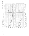
- Fig. 1 gives that for a 40 m pipe with an inner diameter transfer function 10 determined as a function of the frequency again. From this it can be seen that at frequencies of less than 500 Hz, preferably 600 Hz, there is no decrease in the intensity of the acoustic signal, since there is a constant influence of the environment in this frequency range. At frequencies greater than 1680 Hz, a measurement is also no longer possible because there is no longer any sound transmission.
- Fig. 2 shows the results obtained with a tobacco-fed pipe 40 m in length and 12 cm in inside diameter. From the figure it can be seen that the sound intensity of the signal 20 radiated in a narrow frequency range around 1000 Hz from the transmitter (at the feeder, lower illustration) from approximately 110 dB to the receiver (upper illustration) to approximately 90 dB corresponding to a decrease of approximately 0.5 dB / m loaded pipe has dropped.
- a typical circuit diagram 30 for automation is shown in FIG. 3 using the example of cigarette manufacture.
- An acoustic signal is generated by a frequency generator 31, amplified by an amplifier 32, passed through a transmitter multiplexer 33 and emitted by loudspeakers 34 which are provided on feeders 29. If there is a pipe connection, the signal from an acoustic sensor, e.g. B. received a microphone 35 on the relevant strand machine 36 and via an N-channel microphone multiplexer 37, a filter 38, which preferably separates the transmission frequency emitted by the loudspeaker 34 from signals of a different frequency, and an amplifier 39 is forwarded to a threshold value generator 300 .
- the threshold value generator 300 makes a yes / no decision, depending on whether the signal received by the microphone 35 reaches a threshold value or not, and controls it Feeder 29 via a signal relay 301, a pipe section evaluator 302 and a strand machine feeder control 303.
- the control for several pipe sections can be automated by computer-controlled activation of the respective loudspeakers 34 and microphones 35 via multiplexers and a query of the threshold value transmitter 300.
- the speakers 34 and microphones 35 can be controlled via a manual microphone and speaker controller 304.
- the functions required for operation are to be continuously monitored by their own error detection and function or malfunctions are to be displayed, or to be tapped as an error contact in coupling operation with the PLC.
- the modular structure of the monitoring unit should enable the user to exchange and change system components.
- variable obtained from the comparison - the useful signal level greater than the threshold value or the background noise level - yes / no, is to be displayed for manual operation or to be tapped as a signal in coupling operation with the PLC.
- a multi-channel parallel bus based on 24 V DC can be set up for operation with the PLC as master.
- the PLC transfers the number of the string machine microphone 35 and the loudspeaker 34 to a feeder 29 including a measurement release signal.
- the evaluation unit in turn emits signals for, for example, readiness to take measurements, the system is not in order (also manual operation) and there is a connection between the strand machine / loader. For manual operation, there should be setting options for the string machine microphone and the number of the loudspeaker, as well as the start of measurement.
- the transmitters (loudspeakers) and receivers (microphones) required for the pipe monitoring process are commercially available.
- membrane speakers with metal membranes for aggressive media
- speakers can be used as speakers.
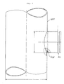
- the microphones 35 and loudspeakers 34 are preferably mounted radially on the tube 400 with a direct access (bore 401) to the interior of the tube (as shown in FIG. 4 using the example of a loudspeaker 34). This attachment of the microphones 35 and the loudspeaker 34 is preferred, since this means that there is no need for any internals in the tube interior which could lead to destruction of the tobacco.
- the loudspeakers should preferably be mounted radially in the feeder in a similar form (socket or housing), as recorded in FIG. 4, with an airtight connection to the respective pipe connection. Attention should be paid to the cramped installation conditions in the feeder (loudspeaker should not be installed outside the feeder, pipe in a vertical installation position), the mechanical stress on the loudspeaker installations due to vibrations of the feeder drive, the environment with the finest tobacco dust, the limited use of plastics and the absolute avoidance of detachable parts that could get into the tobacco as well as attachments or internals that protrude into the inside of the feed pipe.
- the loudspeakers 34 are preferably mounted in the feeder 29 close to the beginning of the pipe socket. When the tobacco is sucked in from the feeder, the tobacco flow is constricted at the beginning of the pipe socket, so that the exposure of the loudspeakers to tobacco dust is kept low.
- the microphone 35 For the preferred installation of the microphone 35 in the immediate vicinity of the strand machine radially on the feed pipe, the points already mentioned for the loudspeaker must be observed.
- the microphone In contrast to the loudspeaker, the microphone is preferably piggybacked on a horizontal pipe section at the top.
- Each loudspeaker and each microphone should be adjustable in terms of sound pressure level and amplification, so that only a threshold value level or a level difference has to be set as a fixed value when evaluating the useful signal level.
- the useful signal sound pressure level of each speaker (e.g. in the feeder) must be adjusted so high during commissioning that at every microphone (e.g. directly on the string machine) there is a difference of at least 10, preferably between the basic sound level and the useful signal sound level after passing through the filter used 15 dB, is measurable.
- the sound pressure level is evaluated under the usual production conditions with a notification time of 8 seconds (linear). With regard to the long-term constancy of the emitted frequency, the loudspeaker must not drift out of the filter selection range of the microphone or vice versa.
- the sound pressure level difference between useful and basic sound pressure levels on the strand machine must not be less than 10 dB.
Landscapes
- Physics & Mathematics (AREA)
- General Physics & Mathematics (AREA)
- Manufacturing Of Cigar And Cigarette Tobacco (AREA)
- Pipeline Systems (AREA)
- Investigating Or Analyzing Materials By The Use Of Ultrasonic Waves (AREA)
Applications Claiming Priority (2)
| Application Number | Priority Date | Filing Date | Title |
|---|---|---|---|
| DE3930424 | 1989-09-12 | ||
| DE3930424A DE3930424A1 (de) | 1989-09-12 | 1989-09-12 | Verfahren zur ueberpruefung des bestehens einer rohrleitungsverbindung zwischen zwei endpunkten |
Publications (2)
| Publication Number | Publication Date |
|---|---|
| EP0417763A2 true EP0417763A2 (fr) | 1991-03-20 |
| EP0417763A3 EP0417763A3 (en) | 1992-05-06 |
Family
ID=6389254
Family Applications (1)
| Application Number | Title | Priority Date | Filing Date |
|---|---|---|---|
| EP19900117561 Withdrawn EP0417763A3 (en) | 1989-09-12 | 1990-09-12 | Procedure to assess the existence of a fixation between to end-points of pipes |
Country Status (9)
| Country | Link |
|---|---|
| US (1) | US5144839A (fr) |
| EP (1) | EP0417763A3 (fr) |
| JP (1) | JPH0769040B2 (fr) |
| KR (1) | KR910006703A (fr) |
| AR (1) | AR247026A1 (fr) |
| AU (1) | AU625087B2 (fr) |
| BR (1) | BR9004478A (fr) |
| DD (1) | DD297706A5 (fr) |
| DE (1) | DE3930424A1 (fr) |
Cited By (1)
| Publication number | Priority date | Publication date | Assignee | Title |
|---|---|---|---|---|
| CN102174992A (zh) * | 2011-01-25 | 2011-09-07 | 黄腾飞 | 一种压力管道的压力曲线特征提取方法 |
Families Citing this family (8)
| Publication number | Priority date | Publication date | Assignee | Title |
|---|---|---|---|---|
| US6626042B2 (en) | 2001-06-14 | 2003-09-30 | Honeywell International Inc. | Communication for water distribution networks |
| US6774814B2 (en) | 2001-06-22 | 2004-08-10 | Network Technologies Group, Llc | Pipe-to-soil testing apparatus and methods |
| US20050135632A1 (en) * | 2003-12-17 | 2005-06-23 | Metravib R.D.S. | Method and apparatus for detecting and locating noise sources not correlated |
| US20070068225A1 (en) | 2005-09-29 | 2007-03-29 | Brown Gregory C | Leak detector for process valve |
| US8899114B2 (en) * | 2009-07-30 | 2014-12-02 | Halliburton Energy Services, Inc. | Energy intensity transformation |
| CN102168809A (zh) * | 2011-01-25 | 2011-08-31 | 黄腾飞 | 一种基于压力温度分析的机场坪航空燃油管网泄漏检测方法及系统 |
| CN102907761B (zh) * | 2012-10-29 | 2014-07-30 | 中科院成都信息技术股份有限公司 | 喂丝机与卷烟机连接关系的检测系统与检测方法 |
| JP2020076784A (ja) * | 2020-01-30 | 2020-05-21 | 三菱重工業株式会社 | 識別システム、振動発生装置、及び識別方法 |
Family Cites Families (14)
| Publication number | Priority date | Publication date | Assignee | Title |
|---|---|---|---|---|
| FR1418225A (fr) * | 1964-10-07 | 1965-11-19 | Perfectionnements apportés aux appareils de mesure utilisant la propagation d'ondes acoustiques dans les milieux à étudier | |
| DE2854238C2 (de) * | 1978-12-15 | 1982-04-08 | Bayerische Motoren Werke AG, 8000 München | Verfahren zum Ermitteln der Dichtheit sowie der Schalldämmung von Abdichtungen zwischen einen Raum begrenzenden Bauteilen |
| US4584676A (en) * | 1982-03-15 | 1986-04-22 | Measurement Systems, Inc. | Method of and apparatus for pipe length measurement |
| US4480473A (en) * | 1983-05-26 | 1984-11-06 | General Motors Corporation | Acoustic inspection method |
| US4678621A (en) * | 1984-03-29 | 1987-07-07 | Combustion Engineering, Inc. | Method and means for monitoring the continuity of a fluid-filled network of conduits and valves |
| DE3444225A1 (de) * | 1984-12-01 | 1986-06-05 | Gerhard 1000 Berlin Thoma | Verfahren zur dichtigkeitspruefung von hohlkoerpern und vorrichtung zu seiner durchfuehrung |
| SU1262359A2 (ru) * | 1985-06-04 | 1986-10-07 | Волго-Уральский научно-исследовательский и проектный институт по добыче и переработке сероводородсодержащих газов | Устройство дл определени сплошности потока жидкости в трубопроводе |
| DE3607913C1 (en) * | 1986-03-10 | 1987-08-13 | Fraunhofer Ges Forschung | Method for locating leaks in pipelines |
| GB2193318A (en) * | 1986-07-31 | 1988-02-03 | Atomic Energy Authority Uk | Monitoring the integrity of mechanical structures |
| JPS6478184A (en) * | 1987-06-24 | 1989-03-23 | Nippon Kokan Kk | Method and device for deriving length of tubular body by utilizing acoustic wave |
| US4845989A (en) * | 1987-09-04 | 1989-07-11 | Titlow Joseph D | Method and apparatus for determining elastic constants in tubes |
| DE3806437A1 (de) * | 1988-02-29 | 1989-08-31 | Bat Cigarettenfab Gmbh | System zur pneumatischen zufuehrung von tabak |
| US4935884A (en) * | 1988-04-28 | 1990-06-19 | Champlin Electronics, Inc. | Sonic pipe length detector |
| US4930350A (en) * | 1988-10-06 | 1990-06-05 | Robert Bode | Acoustical length measurement |
-
1989
- 1989-09-12 DE DE3930424A patent/DE3930424A1/de not_active Withdrawn
-
1990
- 1990-09-07 JP JP2238852A patent/JPH0769040B2/ja not_active Expired - Lifetime
- 1990-09-10 US US07/580,311 patent/US5144839A/en not_active Expired - Fee Related
- 1990-09-10 BR BR909004478A patent/BR9004478A/pt not_active IP Right Cessation
- 1990-09-10 AR AR90317800A patent/AR247026A1/es active
- 1990-09-10 DD DD90343912A patent/DD297706A5/de not_active IP Right Cessation
- 1990-09-11 AU AU62354/90A patent/AU625087B2/en not_active Ceased
- 1990-09-12 KR KR1019900014337A patent/KR910006703A/ko not_active Withdrawn
- 1990-09-12 EP EP19900117561 patent/EP0417763A3/de not_active Withdrawn
Cited By (1)
| Publication number | Priority date | Publication date | Assignee | Title |
|---|---|---|---|---|
| CN102174992A (zh) * | 2011-01-25 | 2011-09-07 | 黄腾飞 | 一种压力管道的压力曲线特征提取方法 |
Also Published As
| Publication number | Publication date |
|---|---|
| JPH03272400A (ja) | 1991-12-04 |
| AU625087B2 (en) | 1992-07-02 |
| BR9004478A (pt) | 1991-09-10 |
| AU6235490A (en) | 1991-03-21 |
| US5144839A (en) | 1992-09-08 |
| JPH0769040B2 (ja) | 1995-07-26 |
| DD297706A5 (de) | 1992-01-16 |
| KR910006703A (ko) | 1991-04-29 |
| AR247026A1 (es) | 1994-10-31 |
| DE3930424A1 (de) | 1991-03-21 |
| EP0417763A3 (en) | 1992-05-06 |
Similar Documents
| Publication | Publication Date | Title |
|---|---|---|
| DE19982582B3 (de) | Reibungsdurchflußmesser | |
| DE2753472A1 (de) | Verfahren zur automatischen eigenueberwachung von zerstoerungsfreien pruefanlagen | |
| DE2906353B2 (de) | Verfahren und Filtersteueranlage zur zyklischen Gegenspülung membranventilbetätigter Filterschläuche | |
| EP0417763A2 (fr) | Procédé pour vérifier l'existence d'une fixation entre deux bouts de tubes | |
| DE19735250A1 (de) | Verfahren zum Betrieb eines Heliumlecksuchers und für die Durchführung dieses Verfahrens geeigneter Heliumlecksucher | |
| DE102012220505B4 (de) | Überwachung eines Kondensatableiters | |
| DE20122895U1 (de) | Messaufnehmer und Vorrichtung zum Messen der Strömungsgeschwindigkeit und/oder des Durchflusses eines Fluids | |
| DE3414247C2 (de) | Vorrichtung zum Messen des Durchmessers von strang- oder stabförmigen Erzeugnissen der tabakverarbeitenden Industrie | |
| AT523861B1 (de) | Vorrichtung zum sammeln von staubproben | |
| DE102009017858A1 (de) | Filtersteuerung mit Reststaubgehaltanzeige | |
| DE2613799C2 (de) | Verfahren zum Einrichten von Ultraschall-Prüfanlagen | |
| DE2544809C3 (de) | Einstecklehre zur Messung des Innendurchmessers einer Behälteröffnung | |
| DE2925128C2 (de) | Einrichtung zur Überwachung der Schließ- und Öffnungsfunktion von Ventilen, die in Abreinigungsimpulsleitungen von Entstaubungseinrichtungen einem Druckluftspeicher nachgeschaltet sind | |
| EP1456631A2 (fr) | Procede et dispositif de suppression et de compensation d'erreurs de signaux parasites dus a la gammagraphie dans des systemes de mesure radiometriques | |
| WO2020043416A1 (fr) | Dispositif d'eaux usées sous vide, procédé et unité de commande électronique pour commander un dispositif d'eaux usées sous vide | |
| DE19963837A1 (de) | Entlüftungsanlage und Verfahren zum Einstellen und Betreiben der Entlüftungsanlage | |
| DE2462281C3 (fr) | ||
| EP3301410B1 (fr) | Localisation d'un événement au niveau du signal de capteur | |
| DE102023127134A1 (de) | Ultraschall-Durchflussmesser | |
| EP3073337B1 (fr) | Dispositif de réglage pour armatures doté de dispositif de traitement et de mesure de bruit du corps de l'armature | |
| DE102023127133A1 (de) | Ultraschall-Durchflussmesser | |
| EP1464842B1 (fr) | Dispositif pour l'obtention d'un vide | |
| DE10358531A1 (de) | Vorrichtung und Verfahren zum Detektieren von Entstehungsbränden | |
| DE2524467C3 (de) | Einrichtung zum Messen der Lautpegeldifferenz zwischen zwei Raumpunkten | |
| DE19939970B4 (de) | Vorrichtung zur Filterung von Öl und zur Abscheidung von Luft aus Öl in Hydrauliksystemen |
Legal Events
| Date | Code | Title | Description |
|---|---|---|---|
| PUAI | Public reference made under article 153(3) epc to a published international application that has entered the european phase |
Free format text: ORIGINAL CODE: 0009012 |
|
| AK | Designated contracting states |
Kind code of ref document: A2 Designated state(s): AT BE CH DE DK ES FR GB GR IT LI LU NL SE |
|
| PUAL | Search report despatched |
Free format text: ORIGINAL CODE: 0009013 |
|
| AK | Designated contracting states |
Kind code of ref document: A3 Designated state(s): AT BE CH DE DK ES FR GB GR IT LI LU NL SE |
|
| 17P | Request for examination filed |
Effective date: 19920616 |
|
| 17Q | First examination report despatched |
Effective date: 19930427 |
|
| STAA | Information on the status of an ep patent application or granted ep patent |
Free format text: STATUS: THE APPLICATION IS DEEMED TO BE WITHDRAWN |
|
| 18D | Application deemed to be withdrawn |
Effective date: 19930908 |