EP0417780A2 - Méthode et appareillage pour évaporer une cathode à décharge par arc présentant des taches cathodiques ayant une émission réduite de macroparticules - Google Patents
Méthode et appareillage pour évaporer une cathode à décharge par arc présentant des taches cathodiques ayant une émission réduite de macroparticules Download PDFInfo
- Publication number
- EP0417780A2 EP0417780A2 EP90117648A EP90117648A EP0417780A2 EP 0417780 A2 EP0417780 A2 EP 0417780A2 EP 90117648 A EP90117648 A EP 90117648A EP 90117648 A EP90117648 A EP 90117648A EP 0417780 A2 EP0417780 A2 EP 0417780A2
- Authority
- EP
- European Patent Office
- Prior art keywords
- cathode
- dam
- lugs
- evaporating
- spots
- Prior art date
- Legal status (The legal status is an assumption and is not a legal conclusion. Google has not performed a legal analysis and makes no representation as to the accuracy of the status listed.)
- Ceased
Links
- 238000001704 evaporation Methods 0.000 title claims abstract description 44
- 238000010891 electric arc Methods 0.000 title claims abstract description 16
- 238000000034 method Methods 0.000 title claims abstract description 16
- 239000007789 gas Substances 0.000 claims abstract description 13
- 239000011261 inert gas Substances 0.000 claims abstract description 4
- 239000010406 cathode material Substances 0.000 claims abstract description 3
- 239000000463 material Substances 0.000 claims description 17
- 230000005291 magnetic effect Effects 0.000 claims description 14
- 239000003302 ferromagnetic material Substances 0.000 claims description 4
- 230000009467 reduction Effects 0.000 abstract description 16
- 238000005516 engineering process Methods 0.000 abstract description 4
- 208000036366 Sensation of pressure Diseases 0.000 abstract description 2
- 239000010410 layer Substances 0.000 description 12
- 239000000758 substrate Substances 0.000 description 9
- IJGRMHOSHXDMSA-UHFFFAOYSA-N Atomic nitrogen Chemical compound N#N IJGRMHOSHXDMSA-UHFFFAOYSA-N 0.000 description 8
- 230000008020 evaporation Effects 0.000 description 7
- NRTOMJZYCJJWKI-UHFFFAOYSA-N Titanium nitride Chemical compound [Ti]#N NRTOMJZYCJJWKI-UHFFFAOYSA-N 0.000 description 4
- 229910052757 nitrogen Inorganic materials 0.000 description 4
- 239000002245 particle Substances 0.000 description 4
- 230000008901 benefit Effects 0.000 description 3
- 239000011247 coating layer Substances 0.000 description 3
- 230000004907 flux Effects 0.000 description 3
- 150000002500 ions Chemical class 0.000 description 3
- 238000000926 separation method Methods 0.000 description 3
- 230000003746 surface roughness Effects 0.000 description 3
- 230000007704 transition Effects 0.000 description 3
- RTAQQCXQSZGOHL-UHFFFAOYSA-N Titanium Chemical compound [Ti] RTAQQCXQSZGOHL-UHFFFAOYSA-N 0.000 description 2
- 230000015572 biosynthetic process Effects 0.000 description 2
- 230000000875 corresponding effect Effects 0.000 description 2
- 230000007797 corrosion Effects 0.000 description 2
- 238000005260 corrosion Methods 0.000 description 2
- 238000000151 deposition Methods 0.000 description 2
- 230000008021 deposition Effects 0.000 description 2
- 238000001179 sorption measurement Methods 0.000 description 2
- 239000010936 titanium Substances 0.000 description 2
- 229910052719 titanium Inorganic materials 0.000 description 2
- 238000000576 coating method Methods 0.000 description 1
- 150000001875 compounds Chemical class 0.000 description 1
- 230000007547 defect Effects 0.000 description 1
- 230000000994 depressogenic effect Effects 0.000 description 1
- 239000000428 dust Substances 0.000 description 1
- 230000005684 electric field Effects 0.000 description 1
- 230000005686 electrostatic field Effects 0.000 description 1
- 238000005530 etching Methods 0.000 description 1
- 238000002513 implantation Methods 0.000 description 1
- 230000007774 longterm Effects 0.000 description 1
- 238000011089 mechanical engineering Methods 0.000 description 1
- 239000002923 metal particle Substances 0.000 description 1
- 238000004377 microelectronic Methods 0.000 description 1
- 239000000203 mixture Substances 0.000 description 1
- 238000005121 nitriding Methods 0.000 description 1
- 230000008569 process Effects 0.000 description 1
- 238000002310 reflectometry Methods 0.000 description 1
- 239000000126 substance Substances 0.000 description 1
Images

Classifications
-
- H—ELECTRICITY
- H01—ELECTRIC ELEMENTS
- H01J—ELECTRIC DISCHARGE TUBES OR DISCHARGE LAMPS
- H01J37/00—Discharge tubes with provision for introducing objects or material to be exposed to the discharge, e.g. for the purpose of examination or processing thereof
- H01J37/32—Gas-filled discharge tubes
- H01J37/32009—Arrangements for generation of plasma specially adapted for examination or treatment of objects, e.g. plasma sources
- H01J37/32055—Arc discharge
-
- C—CHEMISTRY; METALLURGY
- C23—COATING METALLIC MATERIAL; COATING MATERIAL WITH METALLIC MATERIAL; CHEMICAL SURFACE TREATMENT; DIFFUSION TREATMENT OF METALLIC MATERIAL; COATING BY VACUUM EVAPORATION, BY SPUTTERING, BY ION IMPLANTATION OR BY CHEMICAL VAPOUR DEPOSITION, IN GENERAL; INHIBITING CORROSION OF METALLIC MATERIAL OR INCRUSTATION IN GENERAL
- C23C—COATING METALLIC MATERIAL; COATING MATERIAL WITH METALLIC MATERIAL; SURFACE TREATMENT OF METALLIC MATERIAL BY DIFFUSION INTO THE SURFACE, BY CHEMICAL CONVERSION OR SUBSTITUTION; COATING BY VACUUM EVAPORATION, BY SPUTTERING, BY ION IMPLANTATION OR BY CHEMICAL VAPOUR DEPOSITION, IN GENERAL
- C23C14/00—Coating by vacuum evaporation, by sputtering or by ion implantation of the coating forming material
- C23C14/22—Coating by vacuum evaporation, by sputtering or by ion implantation of the coating forming material characterised by the process of coating
- C23C14/24—Vacuum evaporation
- C23C14/32—Vacuum evaporation by explosion; by evaporation and subsequent ionisation of the vapours, e.g. ion-plating
- C23C14/325—Electric arc evaporation
Definitions
- the invention concerns a method and a device for evaporating an arc discharge cathode with cathode spots used e.g. during forming thin layers, and leads to a reduction of a macroparticle mixture, the presence of which in plasma flux causes an increase of thin layer surface roughness and, therefore, their quality reduction.
- Hitherto well-known methods and devices for evaporating an arc discharge cathode utilize, for macroparticle separation from plasma flux, an ion deviation by means of a magnetic field, as stated by I. I. Akcenov et al., Pribory i technika eksperimenta 5, 1978, 236, or of an electrostatic field in accordance with JP 51-44705, while macroparticle motion is substantially rectilinear. Macroparticles are separated and catched on condensing surfaces.
- a further possibility of macroparticle separation is the utilizaton of rotating curtains, as stated by V. N. Cernjajev et al., Elektronnaja technika - Materialy, 5, 1980, 116.
- a common disadvantage of all separation systems is their considerable intricacy and maintenance-load, marked reduction of evaporated material utilization and, on top of it, it is difficult to ensure catching all macroparticles on the condensing surfaces.
- the method of evaporating an arc discharge cathode with cathode spots with reduced macroparticle emission wherein cathode material is evaporated from the cathode evaporating surface in moving cathode spots in vacuum in the presence of a reactive or an inert gas.
- the gist of the invention consists in affecting the evaporating cathode surface by the reactive gas with a partial pressure higher than a critical one, while plasma is electrically held above the cathode evaporating surface.
- the cathode spots and plasma are, in accordance with the invention, further affected above the cathode evaporating surface by a magnetic field.
- the application of the method in accordance with the invention increases the number and velocity of cathode spots motion, and, therefore, a lower local thermal load of the cathode surface in cathode spots occurs and the arc discharge on the cathode proceeds to a mode with a suppressed macroparticle emission.
- the magnetic field affects the trajectory and velocity of cathode spots on the evaporating surface and increases the ionization of gas and metal particles.
- the magnetic field intensity can affect the critical pressure magnitude of the reactive gas.
- the gist of the device for carrying out method according to the invention comprising a cathode placed in a cooled cathode block and an anode variant in principle, consists in that the cathode is formed of two parts, whereof one part is formed by the cathode bottom with an evaporating surface and the other part is formed by a cathode circumferential dam.
- the dam is higher than 5 % of the characteristic cross dimension of the cathode bottom.
- the advantage of this variant consists in that the electric field, formed by the circumferential dam and the cathode bottom, holds the plasma near to the evaporating surface, i.e. the cathode bottom.
- a cathode with a large evaporating surface there is formed in the cathode bottom a system of lugs, the height of which surpasses 5 % of their minimum mutual distance.
- the lugs may be a part of a cooled cathode block, whilst in the cathode bottom there are formed holes corresponding to the lugs, which simplifies the structure of the cathode evaporating bottom.
- the cathode bottom is provided in sliding relation towards the dam and lugs.
- Making the cathode bottom and the dam of the same material results in a simple structure in order to keep the electric holding plasma near to the cathode bottom evaporating surface.
- the dam and/or lugs are made of a material with a higher cathode voltage drop than that of the cathode bottom material.
- the cathode spots move first across the material with a lower cathode voltage drop and, therefore, the evaporation of the circumferential dam and/or lugs is suppressed.
- the dams and/or lugs are formed of ferromagnetic material. In this case the cathode spots are re pelled from the ferromagnetic material by the induced magnetic field, whilst the evaporation of the dams and/or lugs is suppressed and the cathode spots are held on the evaporating surface of the cathode bottom.
- the dams and lugs are in electric contact with the cathode bottom.
- the dams and/or lugs are electrically insulated from the cathode bottom.
- Advantages of the method and the device in accordance with the invention are realized especially in its application for technologies of thin layers.
- the reduction of the macroparticles content during the formation of thin layers greatly improves their properties, especially homogeneity, surface roughness, corrosion resistance and reflectivity. It is important for a variety of practical applications in the field of mechanical engineering (reduction of friction coefficient, reduction of abrasive wear), in chemical industry (increase of corrosion resistance), in microelectronics (reduction of defects, increase of conductance), in the application for forming decorative coatings etc.
- An important reduction of the macroparticle emission enables an effective utilization of the arc discharge with cathode spots as intensive source of ions for ionic technologies, e.g. implantations, ionic nitriding, ionic dust removal and etching and ionic micromechanical working.
- Fig. 1 graphically represents the affection of the cathode in various embodiments by the partial pressure of a reactive gas
- Figs. 2, 3, 4 and 5 represent in sectional views various structural embodiments of cathodes
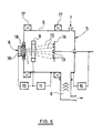
- Fig. 6 schematically represents a device for coating layers on substrates by evaporation of an arc discharge cathode with cathode spots.
- An example of the method according to the invention is given in connection with the description of the device function illustrated in Fig. 6.
- Fig. 1 graphically represents curves of sorbed flow rate of a reactive gas, i.e. N2 nitrogen, in dependence on the s 0 ⁇ N partial pressure P N of nitrogen for a titanium cathode.
- a reactive gas i.e. N2 nitrogen
- the critical pressure P cr is, with given deposition conditions, determinated from the rapid drop of the sorbed nitrogen flow rate.
- the qualitative course of dependence s 0 ⁇ N on P N and, consequently, also the transition of the arc discharge into the regime with depressed emission of macroparticles does not depend on the presence of the inert gas until a partial pressure of a dozen Pa.
- Fig. 2 represents the principal structure of a cathode 1 in accordance with the invention, consisting of two parts.
- the one part is formed by the bottom 2 of the cathode 1 with an evaporating surface, and the other part is formed by a circumferential dam 3.
- the cathode 1 has a characteristic cross dimension 1 and the dam 3 has a height h.
- the dam 3 with its potential holds electrically the plasma above the evaporating surface of the cathode 1.
- Fig. 3 represents a cathode 1 slidable mounted in a dam 3 in a direction normal to the surface of the cathode bottom 2. A loss of material evaporated on the bottom 2 of the cathode 1 is compensated by feeding the whole cathode 1 into the required position.
- Both the cathode 1 and the dam 3 may be made of the same material, or the dam 3 may be made of a material with a higher cathode drop than the material of the cathode bottom 2, or the dam 3 may be formed of a ferromagnetic material.
- the dam 3 can be either in electric contact with the cathode 1 or insulated from the cathode 1.
- Fig. 4 represents a cathode 1 formed by a flat body, e. g. a disk, and is mounted into a circumferential dam 3, so that the bottom 2 of the cathode 1 is firmly connected to the dam 3.
- This arrangement is suited especially for large-surface cathodes 1 with a slow loss of material caused by evaporation of the bottom 2.
- Fig. 5 represents an embodiment suited especially for large-size cathodes.
- the bottom 2 of the cathode 1 is equipped with lugs 4 that are a part of a cooled cathode block 16, whilst in the bottom 2 of the cathode 1 there are formed holes corresponding to the lugs 4.
- Fig. 6 represents a device for coating layers on substrates that consists of a vacuum chamber 5 with a vacuum pump 6 and a working gas supply 7. On a wall of the vacuum chamber 5 there is accommodated a device 8 for evaporation of the arc discharge cathode 1 with reduced emission of macroparticles.
- the dish-shaped cathode 1 is fixed in a cooled cathode block 16 that draws off heat liberated on the cathode during arc discharge.
- the cathode 1 is attached to a supply source 10.
- An auxiliary source 11 holds a voltage between an anode 9 and the metallic wall of the vacuum chamber 5. Also the walls of the metallic vacuum chamber 5 or even substrates 13 may be utilized as anodes.
- the substrates 13 for coating layers are fastened on a carrier 14 that has a potential of a bias source 15.
- the cathode 1 is equipped with a source 18 of magnetic field, formed by a magnetic system with an electromagnet or permanent magnets.
- the operation of the device is explained in an actual example of the method in accordance with the invention for forming a titanium nitride layer.
- the circular cathode 1 of 50 mm diameter with a circumferential dam 3 of 5 mm height has been made of titanium. Nitrogen has been used as reactive gas.
- the substrates 13 have been placed on the carrier 14 in 150 mm distance.
- the arc discharge current was 75 A, the reactive gas pressure was held at 0.5 Pa during the deposition.
- a titanium nitride layer of about 4 ⁇ m thickness was coated on the metallographically polished substrates 13 with a velocity of about 0.1 ⁇ m ⁇ min ⁇ 1.
- the formed titanium nitride layer had a surface roughness of about 0.05 Ra.
- titanium nitride layers of the same thickness formed with hitherto well-known methods have a roughness of a higher order about 0.5 Ra.
Landscapes
- Chemical & Material Sciences (AREA)
- Engineering & Computer Science (AREA)
- Materials Engineering (AREA)
- Plasma & Fusion (AREA)
- Analytical Chemistry (AREA)
- Chemical Kinetics & Catalysis (AREA)
- Physics & Mathematics (AREA)
- Mechanical Engineering (AREA)
- Metallurgy (AREA)
- Organic Chemistry (AREA)
- Physical Vapour Deposition (AREA)
- Plasma Technology (AREA)
- Solid-Phase Diffusion Into Metallic Material Surfaces (AREA)
Applications Claiming Priority (2)
| Application Number | Priority Date | Filing Date | Title |
|---|---|---|---|
| CS528889A CS275226B2 (en) | 1989-09-13 | 1989-09-13 | Method of arc discharge's cathode vaporization with cathode spots and macroparticles' reduced emission and device for realization of this method |
| CS5288/89 | 1989-09-13 |
Publications (2)
| Publication Number | Publication Date |
|---|---|
| EP0417780A2 true EP0417780A2 (fr) | 1991-03-20 |
| EP0417780A3 EP0417780A3 (en) | 1991-05-02 |
Family
ID=5397497
Family Applications (1)
| Application Number | Title | Priority Date | Filing Date |
|---|---|---|---|
| EP19900117648 Ceased EP0417780A3 (en) | 1989-09-13 | 1990-09-13 | Method and device for evaporating an arc discharge cathode with cathode spots with reduced macroparticle emission |
Country Status (3)
| Country | Link |
|---|---|
| EP (1) | EP0417780A3 (fr) |
| JP (1) | JPH03170664A (fr) |
| CS (1) | CS275226B2 (fr) |
Cited By (2)
| Publication number | Priority date | Publication date | Assignee | Title |
|---|---|---|---|---|
| WO1992016959A1 (fr) * | 1991-03-25 | 1992-10-01 | Commonwealth Scientific And Industrial Research Organisation | Filtre pour macroparticules de source a arc |
| EP0548032A3 (fr) * | 1991-12-13 | 1993-07-28 | UNICOAT S.r.l. | Dispositif d'évaporation par décharge d'arc |
Family Cites Families (4)
| Publication number | Priority date | Publication date | Assignee | Title |
|---|---|---|---|---|
| GB2106545B (en) * | 1981-02-23 | 1985-06-26 | Rimma Ivanovna Stupak | Consumable cathode for electric-arc evaporator of metal |
| US4512867A (en) * | 1981-11-24 | 1985-04-23 | Andreev Anatoly A | Method and apparatus for controlling plasma generation in vapor deposition |
| FR2556373B1 (fr) * | 1983-12-07 | 1989-09-08 | Vac Tec Syst | Procede ameliore et appareil pour la stabilisation d'un arc de pulverisation de cibles non permeables a l'aide d'un anneau d'arret permeable |
| DE3672819D1 (de) * | 1985-09-30 | 1990-08-23 | Union Carbide Corp | Vorrichtung und verfahren zum beschichten in einer vakuumkammer durch lichtbogendampfniederschlag. |
-
1989
- 1989-09-13 CS CS528889A patent/CS275226B2/cs unknown
-
1990
- 1990-09-12 JP JP24017590A patent/JPH03170664A/ja active Pending
- 1990-09-13 EP EP19900117648 patent/EP0417780A3/en not_active Ceased
Cited By (2)
| Publication number | Priority date | Publication date | Assignee | Title |
|---|---|---|---|---|
| WO1992016959A1 (fr) * | 1991-03-25 | 1992-10-01 | Commonwealth Scientific And Industrial Research Organisation | Filtre pour macroparticules de source a arc |
| EP0548032A3 (fr) * | 1991-12-13 | 1993-07-28 | UNICOAT S.r.l. | Dispositif d'évaporation par décharge d'arc |
Also Published As
| Publication number | Publication date |
|---|---|
| EP0417780A3 (en) | 1991-05-02 |
| JPH03170664A (ja) | 1991-07-24 |
| CS275226B2 (en) | 1992-02-19 |
Similar Documents
| Publication | Publication Date | Title |
|---|---|---|
| US5114556A (en) | Deposition apparatus and method for enhancing step coverage and planarization on semiconductor wafers | |
| US6787010B2 (en) | Non-thermionic sputter material transport device, methods of use, and materials produced thereby | |
| US4179351A (en) | Cylindrical magnetron sputtering source | |
| US4842703A (en) | Magnetron cathode and method for sputter coating | |
| US4871433A (en) | Method and apparatus for improving the uniformity ion bombardment in a magnetron sputtering system | |
| US4420386A (en) | Method for pure ion plating using magnetic fields | |
| US5972185A (en) | Cathodic arc vapor deposition apparatus (annular cathode) | |
| KR100559285B1 (ko) | 캐소우드아크증착장치 | |
| US4810347A (en) | Penning type cathode for sputter coating | |
| KR101344085B1 (ko) | 성막 방법 및 성막 장치 | |
| US4622122A (en) | Planar magnetron cathode target assembly | |
| KR20110135919A (ko) | 아크 증발원의 변형 가능한 자석 배치 | |
| EP0417780A2 (fr) | Méthode et appareillage pour évaporer une cathode à décharge par arc présentant des taches cathodiques ayant une émission réduite de macroparticules | |
| KR100530545B1 (ko) | 캐소우드아크증착장치 | |
| EP1211332A1 (fr) | Unite magnetron et dispositif de pulverisation cathodique | |
| WO1990013137A1 (fr) | Appareil de pulverisation | |
| US4476000A (en) | Method of making a magnetic film target for sputtering | |
| KR20060066632A (ko) | 기판에 재료를 캐소드 아크 증착시키기 위한 방법 및 장치 | |
| JPH1136063A (ja) | アーク式蒸発源 | |
| EP1252357A1 (fr) | Cible de pulverisation conique | |
| JPH03260064A (ja) | 電気アーク蒸発器 | |
| KR100489299B1 (ko) | 고속 증발이 가능한 마그네트론 스퍼터링 증발원 | |
| SU1580866A1 (ru) | Устройство дл ионно-плазменного распылени ферромагнитных материалов | |
| EP0745148A1 (fr) | Procede et appareil de pulverisation cathodique pour depot d'un revetement sur un substrat | |
| PL142541B1 (en) | Apparatus for application thin films of metals,dielectrics and semiconductors using cathode sputtering method |
Legal Events
| Date | Code | Title | Description |
|---|---|---|---|
| PUAI | Public reference made under article 153(3) epc to a published international application that has entered the european phase |
Free format text: ORIGINAL CODE: 0009012 |
|
| PUAL | Search report despatched |
Free format text: ORIGINAL CODE: 0009013 |
|
| AK | Designated contracting states |
Kind code of ref document: A2 Designated state(s): BE CH DE GB LI NL |
|
| AK | Designated contracting states |
Kind code of ref document: A3 Designated state(s): BE CH DE GB LI NL |
|
| 17P | Request for examination filed |
Effective date: 19911023 |
|
| 17Q | First examination report despatched |
Effective date: 19930312 |
|
| RAP1 | Party data changed (applicant data changed or rights of an application transferred) |
Owner name: HVM PLASMA, LTD. |
|
| STAA | Information on the status of an ep patent application or granted ep patent |
Free format text: STATUS: THE APPLICATION HAS BEEN REFUSED |
|
| 18R | Application refused |
Effective date: 19941001 |